Jig Boring Machine
ProductOverview
A jig boring machine is the most accurate hole-making machine in the workshop. Its purpose is to locate and finish holes whose position must be correct to a few microns, the level of accuracy needed for jigs, fixtures, press dies, gauges, and precision instrument parts. Where a milling machine positions a hole to a few hundredths of a millimetre, a jig borer holds the centre distance between two holes to one or two thousandths of a millimetre, and finishes the bore itself round and straight to the same order. It does this by combining an extremely precise coordinate table, a near-perfect spindle, direct length measurement, and tight control of temperature, since at this accuracy a one-degree change in the machine moves the work by more than the tolerance allowed.
Historically the jig borer was the master machine that made the tools other machines used. A toolmaker would bore a hardened jig plate on a jig borer, and that plate would then guide drills on production machines to put holes in thousands of parts. The accuracy of the jig borer set the accuracy of everything downstream.
Base and structure
Accuracy begins with stability, so the Base & Foundation is a massive Base Casting of granite or seasoned cast iron, chosen for thermal stability and resistance to vibration, standing on Vibration Isolator that isolate it from floor movement and a Leveling Set that levels it to arc-seconds. The Bridge Column is a symmetrical Column Casting carrying the Spindle Head on guideways from the shared Linear Guide Rail leaf. Symmetry matters because it makes the machine expand evenly as it warms, keeping the spindle over the same point on the table.
Precision spindle
The Precision Spindle is the heart of the machine. The Spindle Shaft is hardened, ground, and lapped to sub-micron runout, running in preloaded Precision Bearing angular contact bearings of class P4 or finer. The spindle feeds the tool down through a lapped Precision Quill that slides without measurable play, driven by a smooth Spindle Motor. Bores are cut by a Boring Head, a micro-adjustable head that sets the diameter in steps of 0.002 mm so the operator can sneak up on the exact size. Spindle quality is what makes the finished bore round and straight rather than merely well-located.
Coordinate table and positioning
The workpiece is positioned by the Coordinate Table. A Table Top sits on a stacked X Slide and Y Slide running on the shared Linear Guide Rail leaf, driven by Precision Ball Screw screws turned by the shared Servo Motor leaf. The table moves the part so the next hole centre comes exactly under the fixed spindle, working in Cartesian coordinates, which is where the machine gets its name.
Position measuring system
What separates a jig borer from an ordinary machine is the Position Measuring System system. Position is not taken from the ball screw, because a screw has pitch error and wear; instead a Glass Scale on each axis is read by an optical Optical Read Head and an Interpolator divides the scale signal down to fractions of a micron. The operator sets a datum on the part with an Edge Finder, then moves to each hole by coordinate. Because the length is measured directly against a precision scale, the centre distance between two holes is held to one or two microns regardless of screw error.
Quill feed
The boring cut is made by the Quill (Z) Drive, which feeds the quill down through a fine-pitch Quill Feed Screw driven by the Quill Feed Servo, with a Quill Scale reading depth and a Quill Counterbalance taking the quill weight off the feed so motion stays smooth and free of stick-slip. A jerky feed would leave marks in a bore that is supposed to be mirror-finished.
Thermal stabilisation
At micron accuracy, heat is the enemy. A steel part a metre long grows about 11 microns for every degree it warms, which is several times the tolerance the machine is built to hold. The Thermal Stabilisation system fights this by circulating temperature-controlled oil over the structure through an Oil Shower, holding it constant with a Precision Chiller to a tenth of a degree, watching the structure with Temperature Sensor sensors, and shielding the whole machine in a Thermal Enclosure. Jig borers are normally installed in a temperature-controlled room held at 20 degrees.
Control and use
The CNC Control CNC, built on a CNC Computer computer with a Drive Cabinet and an Operator Panel, does more than move axes: it applies volumetric error compensation, correcting for the tiny, mapped geometric errors of the machine and for the readings of the temperature sensors so the commanded position matches the real position to the micron. In use the toolmaker clamps a part, sets a datum, and bores each hole to coordinate, measuring as they go. The machine is slow and deliberate by design, because at this accuracy every cut and every minute of thermal settling matters, and that patience is what produces the master tooling on which faster production depends.
Jig Boring Machine parts and their functions
8 top-level parts · 553 parts in total · full bill of materials below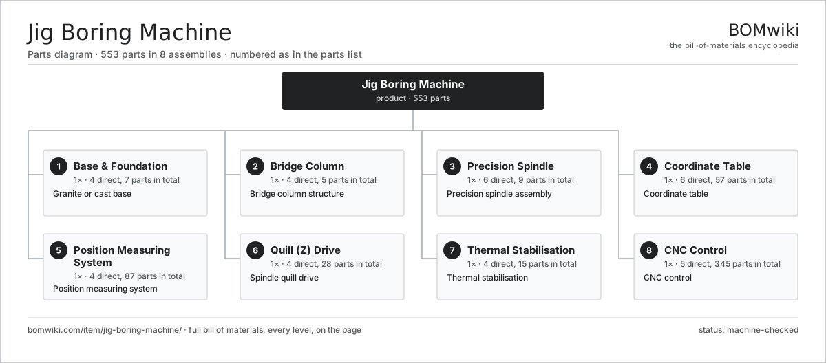
| # | Part | Qty | What it does |
|---|---|---|---|
| 1 | Base & Foundation 4 parts | 1× | Granite or cast base |
| 2 | Bridge Column 4 parts | 1× | Bridge column structure |
| 3 | Precision Spindle 6 parts | 1× | Precision spindle assembly |
| 4 | Coordinate Table 6 parts | 1× | Coordinate table |
| 5 | Position Measuring System 4 parts | 1× | Position measuring system |
| 6 | Quill (Z) Drive 4 parts | 1× | Spindle quill drive |
| 7 | Thermal Stabilisation 4 parts | 1× | Thermal stabilisation |
| 8 | CNC Control 5 parts | 1× | CNC control |
3D model
No 3D model yet. Have a CAD file of this? Add a 3D model — STL renders right on this page; STEP, FreeCAD, and OpenSCAD sources are welcome too (openly licensed, like all 3D models on BOMwiki).
Build & assembly graph
expand / collapse · shared sub-assemblies converge · links to related products · est. labourTap an assembly to expand/collapse · tap a part to open it · use “Open page” for any node · drag to pan, scroll to zoom.
Bill of materials for Jig Boring Machine
8 top-level lines · 65 rows shown · 553 parts total · indented to 3 levels| # | Item / sub-assembly | Part no. | Qty/assy | Ext. qty | Parts | Type |
|---|---|---|---|---|---|---|
| 1 | Base & Foundation 4 parts | jig-boring-machine-base | 1× | 1 | 7 | assembly |
| 1.1 | Base Casting | jig-boring-machine-base-casting | 1× | 1 | · | part |
| 1.2 | Vibration Isolator | jig-boring-machine-isolators | 4× | 4 | · | part |
| 1.3 | Leveling Set | jig-boring-machine-leveling-set | 1× | 1 | · | part |
| 1.4 | Fastener Set | fastener-set | 1× | 1 | · | part |
| 2 | Bridge Column 4 parts | jig-boring-machine-column | 1× | 1 | 5 | assembly |
| 2.1 | Column Casting | jig-boring-machine-column-casting | 1× | 1 | · | part |
| 2.2 | Spindle Head | jig-boring-machine-spindle-head | 1× | 1 | · | part |
| 2.3 | Linear Guide Rail | linear-guide | 2× | 2 | · | part |
| 2.4 | Head Screw | jig-boring-machine-head-screw | 1× | 1 | · | part |
| 3 | Precision Spindle 6 parts | jig-boring-machine-spindle | 1× | 1 | 9 | assembly |
| 3.1 | Spindle Shaft | jig-boring-machine-spindle-shaft | 1× | 1 | · | part |
| 3.2 | Precision Bearing | jig-boring-machine-precision-bearing | 4× | 4 | · | part |
| 3.3 | Precision Quill | jig-boring-machine-quill | 1× | 1 | · | part |
| 3.4 | Spindle Motor | jig-boring-machine-spindle-motor | 1× | 1 | · | part |
| 3.5 | Tool Holder | jig-boring-machine-toolholder | 1× | 1 | · | part |
| 3.6 | Boring Head | jig-boring-machine-boring-head | 1× | 1 | · | part |
| 4 | Coordinate Table 6 parts | jig-boring-machine-xy-table | 1× | 1 | 57 | assembly |
| 4.1 | Table Top | jig-boring-machine-table-top | 1× | 1 | · | part |
| 4.2 | X Slide | jig-boring-machine-x-slide | 1× | 1 | · | part |
| 4.3 | Y Slide | jig-boring-machine-y-slide | 1× | 1 | · | part |
| 4.4 | Precision Ball Screw | jig-boring-machine-precision-ballscrew | 2× | 2 | · | part |
| 4.5 | Linear Guide Rail | linear-guide | 4× | 4 | · | part |
| 4.6 | Servo Motor 4 parts | servo-motor | 2× | 2 | 24 | assembly |
| 4.6.1 | Stator Assembly 3 parts + deeper › | stator-assembly | 1× | 2 | 3 | assembly |
| 4.6.2 | Rotor Assembly 4 parts + deeper › | rotor-assembly | 1× | 2 | 19 | assembly |
| 4.6.3 | Encoder | encoder | 1× | 2 | · | part |
| 4.6.4 | Motor Housing | motor-housing | 1× | 2 | · | part |
| 5 | Position Measuring System 4 parts | jig-boring-machine-measuring | 1× | 1 | 87 | assembly |
| 5.1 | Glass Scale | jig-boring-machine-glass-scale | 2× | 2 | · | part |
| 5.2 | Optical Read Head | jig-boring-machine-read-head | 2× | 2 | · | part |
| 5.3 | Interpolator 3 parts | jig-boring-machine-interpolator | 1× | 1 | 82 | assembly |
| 5.3.1 | Bare PCB | pcb-bare | 1× | 1 | · | part |
| 5.3.2 | Microcontroller | mcu | 1× | 1 | · | part |
| 5.3.3 | SMD Passive (R/C/L) | smd-passives | 80× | 80 | · | part |
| 5.4 | Edge Finder | jig-boring-machine-edge-finder | 1× | 1 | · | part |
| 6 | Quill (Z) Drive 4 parts | jig-boring-machine-z-drive | 1× | 1 | 28 | assembly |
| 6.1 | Quill Feed Screw | jig-boring-machine-z-screw | 1× | 1 | · | part |
| 6.2 | Quill Feed Servo 2 parts | jig-boring-machine-z-motor | 1× | 1 | 25 | assembly |
| 6.2.1 | Servo Motor 4 parts + deeper › | servo-motor | 1× | 1 | 24 | assembly |
| 6.2.2 | Ball Bearing | ball-bearing | 1× | 1 | · | part |
| 6.3 | Quill Scale | jig-boring-machine-z-scale | 1× | 1 | · | part |
| 6.4 | Quill Counterbalance | jig-boring-machine-quill-counterbalance | 1× | 1 | · | part |
| 7 | Thermal Stabilisation 4 parts | jig-boring-machine-temp-control | 1× | 1 | 15 | assembly |
| 7.1 | Oil Shower | jig-boring-machine-oil-shower | 1× | 1 | · | part |
| 7.2 | Precision Chiller | jig-boring-machine-chiller | 1× | 1 | · | part |
| 7.3 | Temperature Sensor | jig-boring-machine-temp-sensor | 6× | 6 | · | part |
| 7.4 | Thermal Enclosure 2 parts | jig-boring-machine-enclosure | 1× | 1 | 7 | assembly |
| 7.4.1 | Sheet Metal Panel | sheet-panel | 6× | 6 | · | part |
| 7.4.2 | Fastener Set | fastener-set | 1× | 1 | · | part |
| 8 | CNC Control 5 parts | jig-boring-machine-control | 1× | 1 | 345 | assembly |
| 8.1 | CNC Computer 3 parts | jig-boring-machine-cnc | 1× | 1 | 153 | assembly |
| 8.1.1 | Bare PCB | pcb-bare | 1× | 1 | · | part |
| 8.1.2 | Microcontroller | mcu | 2× | 2 | · | part |
| 8.1.3 | SMD Passive (R/C/L) | smd-passives | 150× | 150 | · | part |
| 8.2 | Drive Cabinet 3 parts | jig-boring-machine-drive-cabinet | 1× | 1 | 128 | assembly |
| 8.2.1 | Bare PCB | pcb-bare | 2× | 2 | · | part |
| 8.2.2 | Relay | relay | 6× | 6 | · | part |
| 8.2.3 | SMD Passive (R/C/L) | smd-passives | 120× | 120 | · | part |
| 8.3 | Operator Panel 3 parts | jig-boring-machine-operator-panel | 1× | 1 | 62 | assembly |
| 8.3.1 | LCD Panel | lcd-panel | 1× | 1 | · | part |
| 8.3.2 | Bare PCB | pcb-bare | 1× | 1 | · | part |
| 8.3.3 | SMD Passive (R/C/L) | smd-passives | 60× | 60 | · | part |
| 8.4 | Power Supply | power-supply | 1× | 1 | · | part |
| 8.5 | Wire Bundle | wire-bundle | 1× | 1 | · | part |
Related products
same domain, ranked by shared parts CO2 Laser Cutting Machine
227 parts · shares 4 with this page
CO2 Laser Cutting Machine
227 parts · shares 4 with this page
 Compression Spring Coiler
1,167 parts · shares 4 with this page
Compression Spring Coiler
1,167 parts · shares 4 with this page
Sourcing: possible vendors
Prices, MOQ, and lead times are algorithmic estimates, not quotes, and not claims about these companies. Company mappings are curated by keyword; est. price band $10k–$1M. How estimates work| Vendor | HQ | Specialty | MOQ | Lead time |
|---|---|---|---|---|
|
🇩🇪DMG MORI
dmgmori.com ↗
|
Bielefeld, DE | Machine tools | 5 units | 12–20 wks |
|
🇯🇵Mazak
mazak.com ↗
|
Oguchi, JP | Machine tools | 5 units | 12–20 wks |
| haascnc.com ↗ | Oxnard, US | CNC machine tools | 5 units | 12–20 wks |
|
🇯🇵Okuma
okuma.com ↗
|
Niwa, JP | Machine tools | 5 units | 12–20 wks |
|
🇩🇪Trumpf
trumpf.com ↗
|
Ditzingen, DE | Laser & sheet-metal machines | 5 units | 12–20 wks |
945-word article