Vibratory Deburring Tumbler
ProductOverview
A vibratory deburring tumbler finishes parts in bulk by shaking them together with loose abrasive media. The parts and the media share a single bowl, and the machine vibrates the whole charge so the media rubs against every surface at once. Where two pieces of media pinch an edge, they knock the burr off and roll the corner into a small radius; over a longer run the same rubbing brings the surface up to a polish. Because the action reaches every face of every part without anyone touching them, one machine can deburr a basket of stampings, radius the edges of machined brackets, or polish castings, all while the operator does something else. The work happens in the Vibratory Bowl, and a few hundred kilograms of charge are kept moving by a single out-of-balance motor.
The bowl is a torus, a ring with a channel running around it, mounted on Coil Spring isolators so it can shake freely. A Vibratory Drive under the bowl spins eccentric weights that vibrate it thousands of times a minute. That vibration does two things at once: it makes the media and parts rub, and it makes the whole charge climb the outer wall and roll back down, spiralling slowly forward around the ring. The forward roll is what carries parts to the discharge when the cycle ends.
The bowl and the spiral roll
The Bowl Shell is a welded steel torus, and inside it a thick Polyurethane Lining is cast against the steel. The lining matters more than it looks: bare steel would bruise the parts and wear out fast under the constant pounding of ceramic media, so a 60 Shore A polyurethane layer takes the impact, resists the abrasive, and keeps the parts clean. Cast into the lining is a Spiral Process Channel, a helical groove that turns the shaking into a directed roll. As the bowl vibrates, the charge does not just churn in place; it walks forward along the channel toward the Media Separation Deck. A Splash Lid keeps water and media from splashing out, and two Drain Port outlets let spent water and fines run off.
How the vibration is made
The whole machine runs off one Out-of-Balance Motor, a motor built to spin with deliberately unbalanced loads on its shaft ends. A Top Eccentric Weight and a Bottom Eccentric Weight are bolted to the Vertical Drive Shaft, and as they spin their offset mass throws the bowl in a circular shake about 24 times a second. The size of the weights sets the amplitude, typically 3 to 6 mm: bigger throw means harder rubbing and faster cutting. The clever part is the angle between the top and bottom weights. Lead the bottom weight ahead of the top one and the charge spirals forward faster; line them up and it barely advances and just churns in place. So one adjustment controls both how aggressively the media cuts and how quickly parts move toward the exit. The Ball Bearing pairs and Oil Seal units carry the shaft and keep media out of the motor.
Springs, separation and fluid
All of that shaking has to stay in the bowl. The bowl sits on six Coil Spring isolators in the Spring Isolation Base, which let the bowl move freely while passing very little vibration into the floor; Anti-Walk Mount pads under the frame stop the machine from walking. When the cycle ends, the charge rolls out over the Media Separation Deck, a vibrating Separation Screen sized so the small media drops through and returns to the bowl while the larger finished parts ride over the top into the Parts Collection Bin. A Ferrous Catch Magnet under the deck pulls out broken ferrous media and chips. Throughout the run the Process Water & Compound System meters water and a liquid compound into the bowl: the water flushes away fines and keeps the parts from staining, and the Compound Dosing Pump adds compound that lubricates the cut and sets whether the run deburrs aggressively or brightens to a shine. Spent water drops its solids in the Settling Tank before it is decanted.
Materials and media
The media is the cutting tool, and it is chosen to match the job. Ceramic shapes, cones and triangles and wedges, cut fast and are used for deburring and heavy stock removal on steel and iron. Plastic media cuts gentler and suits soft metals like aluminium and brass. Porcelain balls and dry corn-cob or walnut- shell media are used for the final polish, where almost no metal comes off and the point is shine. Shape is picked so the media reaches into the part: small cones get into corners and bores, while large wedges suit flat open faces. The machine itself is built to survive the constant pounding, hence the cast steel Top Eccentric Weight and Bottom Eccentric Weight and the 42CrMo4 Vertical Drive Shaft.
Control, unload and noise
The Control Panel sets the cycle time, the water flush and compound dose, and the motor speed through a Variable Frequency Drive, then runs the Media Separation Deck and the Unload Mechanism at the end. Unloading is automatic: a Discharge Gate in the spiral channel opens, and instead of recirculating, the spiralling charge runs out over the screen. Because hundreds of kilograms of ceramic rattling against steel is loud, the bowl runs inside a Sound Enclosure lined with Acoustic Lining, which brings the running level under 78 dB(A). A Door Interlock stops the drive while the door is open, and the Emergency Stop cuts power at once.
Vibratory Deburring Tumbler parts and their functions
9 top-level parts · 322 parts in total · full bill of materials below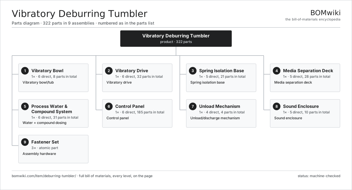
| # | Part | Qty | What it does |
|---|---|---|---|
| 1 | Vibratory Bowl 6 parts | 1× | Vibratory bowl/tub |
| 2 | Vibratory Drive 6 parts | 1× | Vibratory drive |
| 3 | Spring Isolation Base 5 parts | 1× | Spring isolation base |
| 4 | Media Separation Deck 5 parts | 1× | Media separation deck |
| 5 | Process Water & Compound System 6 parts | 1× | Water + compound dosing |
| 6 | Control Panel 6 parts | 1× | Control panel |
| 7 | Unload Mechanism 4 parts | 1× | Unload/discharge mechanism |
| 8 | Sound Enclosure 5 parts | 1× | Sound enclosure |
| 9 | Fastener Set | 3× | Assembly hardware |
3D model
No 3D model yet. Have a CAD file of this? Add a 3D model — STL renders right on this page; STEP, FreeCAD, and OpenSCAD sources are welcome too (openly licensed, like all 3D models on BOMwiki).
Build & assembly graph
expand / collapse · shared sub-assemblies converge · links to related products · est. labourTap an assembly to expand/collapse · tap a part to open it · use “Open page” for any node · drag to pan, scroll to zoom.
Bill of materials for Vibratory Deburring Tumbler
9 top-level lines · 70 rows shown · 322 parts total · indented to 3 levels| # | Item / sub-assembly | Part no. | Qty/assy | Ext. qty | Parts | Type |
|---|---|---|---|---|---|---|
| 1 | Vibratory Bowl 6 parts | deburring-tumbler-bowl | 1× | 1 | 8 | assembly |
| 1.1 | Bowl Shell | deburring-tumbler-bowl-shell | 1× | 1 | · | part |
| 1.2 | Polyurethane Lining | deburring-tumbler-pu-lining | 1× | 1 | · | part |
| 1.3 | Spiral Process Channel | deburring-tumbler-spiral-channel | 1× | 1 | · | part |
| 1.4 | Splash Lid | deburring-tumbler-lid | 1× | 1 | · | part |
| 1.5 | Drain Port | deburring-tumbler-drain-port | 2× | 2 | · | part |
| 1.6 | Fastener Set | fastener-set | 2× | 2 | · | part |
| 2 | Vibratory Drive 6 parts | deburring-tumbler-drive | 1× | 1 | 32 | assembly |
| 2.1 | Out-of-Balance Motor 4 parts | deburring-tumbler-vibratory-motor | 1× | 1 | 25 | assembly |
| 2.1.1 | Stator Assembly 3 parts + deeper › | stator-assembly | 1× | 1 | 3 | assembly |
| 2.1.2 | Rotor Assembly 4 parts + deeper › | rotor-assembly | 1× | 1 | 19 | assembly |
| 2.1.3 | Motor Housing | motor-housing | 1× | 1 | · | part |
| 2.1.4 | Ball Bearing | ball-bearing | 2× | 2 | · | part |
| 2.2 | Top Eccentric Weight | deburring-tumbler-top-weight | 1× | 1 | · | part |
| 2.3 | Bottom Eccentric Weight | deburring-tumbler-bottom-weight | 1× | 1 | · | part |
| 2.4 | Vertical Drive Shaft | deburring-tumbler-shaft | 1× | 1 | · | part |
| 2.5 | Ball Bearing | ball-bearing | 2× | 2 | · | part |
| 2.6 | Oil Seal | oil-seal | 2× | 2 | · | part |
| 3 | Spring Isolation Base 5 parts | deburring-tumbler-spring-base | 1× | 1 | 21 | assembly |
| 3.1 | Base Frame | deburring-tumbler-base-frame | 1× | 1 | · | part |
| 3.2 | Coil Spring | coil-spring | 6× | 6 | · | part |
| 3.3 | Spring Seat | deburring-tumbler-spring-cup | 6× | 6 | · | part |
| 3.4 | Leveling Foot | deburring-tumbler-leveling-foot | 4× | 4 | · | part |
| 3.5 | Anti-Walk Mount | deburring-tumbler-vibration-mount | 4× | 4 | · | part |
| 4 | Media Separation Deck 5 parts | deburring-tumbler-separation-deck | 1× | 1 | 28 | assembly |
| 4.1 | Screen Deck Frame | deburring-tumbler-screen-deck | 1× | 1 | · | part |
| 4.2 | Separation Screen | deburring-tumbler-screen-mesh | 1× | 1 | · | part |
| 4.3 | Media Return Chute | deburring-tumbler-return-chute | 1× | 1 | · | part |
| 4.4 | Deck Vibrator 3 parts | deburring-tumbler-deck-motor | 1× | 1 | 24 | assembly |
| 4.4.1 | Stator Assembly 3 parts + deeper › | stator-assembly | 1× | 1 | 3 | assembly |
| 4.4.2 | Rotor Assembly 4 parts + deeper › | rotor-assembly | 1× | 1 | 19 | assembly |
| 4.4.3 | Ball Bearing | ball-bearing | 2× | 2 | · | part |
| 4.5 | Ferrous Catch Magnet | deburring-tumbler-magnet-bar | 1× | 1 | · | part |
| 5 | Process Water & Compound System 6 parts | deburring-tumbler-fluid-system | 1× | 1 | 31 | assembly |
| 5.1 | Water Inlet Valve | deburring-tumbler-water-valve | 1× | 1 | · | part |
| 5.2 | Compound Dosing Pump 3 parts | deburring-tumbler-dosing-pump | 1× | 1 | 23 | assembly |
| 5.2.1 | Stator Assembly 3 parts + deeper › | stator-assembly | 1× | 1 | 3 | assembly |
| 5.2.2 | Rotor Assembly 4 parts + deeper › | rotor-assembly | 1× | 1 | 19 | assembly |
| 5.2.3 | Pump Tube | deburring-tumbler-pump-tube | 1× | 1 | · | part |
| 5.3 | Compound Tank | deburring-tumbler-compound-tank | 1× | 1 | · | part |
| 5.4 | Water Flow Meter | deburring-tumbler-flow-meter | 1× | 1 | · | part |
| 5.5 | Settling Tank | deburring-tumbler-settling-tank | 1× | 1 | · | part |
| 5.6 | Fluid Hose | deburring-tumbler-fluid-hose | 4× | 4 | · | part |
| 6 | Control Panel 6 parts | deburring-tumbler-control | 1× | 1 | 185 | assembly |
| 6.1 | PLC Controller 4 parts | deburring-tumbler-controller | 1× | 1 | 128 | assembly |
| 6.1.1 | Bare PCB | pcb-bare | 1× | 1 | · | part |
| 6.1.2 | Microcontroller | mcu | 1× | 1 | · | part |
| 6.1.3 | Relay | relay | 6× | 6 | · | part |
| 6.1.4 | SMD Passive (R/C/L) | smd-passives | 120× | 120 | · | part |
| 6.2 | Variable Frequency Drive | deburring-tumbler-vfd | 1× | 1 | · | part |
| 6.3 | Operator Panel 3 parts | deburring-tumbler-hmi | 1× | 1 | 42 | assembly |
| 6.3.1 | Bare PCB | pcb-bare | 1× | 1 | · | part |
| 6.3.2 | LCD Panel | lcd-panel | 1× | 1 | · | part |
| 6.3.3 | SMD Passive (R/C/L) | smd-passives | 40× | 40 | · | part |
| 6.4 | Power Supply | power-supply | 1× | 1 | · | part |
| 6.5 | Wire Bundle | wire-bundle | 1× | 1 | · | part |
| 6.6 | Connector | connector | 12× | 12 | · | part |
| 7 | Unload Mechanism 4 parts | deburring-tumbler-unload | 1× | 1 | 4 | assembly |
| 7.1 | Discharge Gate | deburring-tumbler-discharge-gate | 1× | 1 | · | part |
| 7.2 | Gate Actuator 1 parts | deburring-tumbler-gate-cylinder | 1× | 1 | · | part |
| 7.2.1 | O-Ring Set | oring-set | 1× | 1 | · | part |
| 7.3 | Parts Collection Bin | deburring-tumbler-parts-bin | 1× | 1 | · | part |
| 7.4 | Flow Deflector | deburring-tumbler-flip-deflector | 1× | 1 | · | part |
| 8 | Sound Enclosure 5 parts | deburring-tumbler-enclosure | 1× | 1 | 10 | assembly |
| 8.1 | Sheet Metal Panel | sheet-panel | 6× | 6 | · | part |
| 8.2 | Acoustic Lining | deburring-tumbler-acoustic-foam | 1× | 1 | · | part |
| 8.3 | Access Door | deburring-tumbler-access-door | 1× | 1 | · | part |
| 8.4 | Door Interlock | deburring-tumbler-interlock | 1× | 1 | · | part |
| 8.5 | Emergency Stop | deburring-tumbler-estop | 1× | 1 | · | part |
| 9 | Fastener Set | fastener-set | 3× | 3 | · | part |
Related products
same domain, ranked by shared parts Centrifugal Disc Finishing Machine
326 parts · shares 4 with this page
Centrifugal Disc Finishing Machine
326 parts · shares 4 with this page
 Continuous Belt Furnace
130 parts · shares 4 with this page
Continuous Belt Furnace
130 parts · shares 4 with this page
 Crankshaft Grinder
511 parts · shares 4 with this page
Crankshaft Grinder
511 parts · shares 4 with this page
 Creep-Feed Grinder
571 parts · shares 4 with this page
Creep-Feed Grinder
571 parts · shares 4 with this page
Sourcing: possible vendors
Prices, MOQ, and lead times are algorithmic estimates, not quotes, and not claims about these companies. Company mappings are curated by keyword; est. price band $10k–$1M. How estimates work| Vendor | HQ | Specialty | MOQ | Lead time |
|---|---|---|---|---|
|
🇩🇪DMG MORI
dmgmori.com ↗
|
Bielefeld, DE | Machine tools | 5 units | 12–20 wks |
|
🇯🇵Mazak
mazak.com ↗
|
Oguchi, JP | Machine tools | 5 units | 12–20 wks |
| haascnc.com ↗ | Oxnard, US | CNC machine tools | 5 units | 12–20 wks |
|
🇯🇵Okuma
okuma.com ↗
|
Niwa, JP | Machine tools | 5 units | 12–20 wks |
|
🇩🇪Trumpf
trumpf.com ↗
|
Ditzingen, DE | Laser & sheet-metal machines | 5 units | 12–20 wks |
968-word article