Horizontal Boring Machine
ProductAlso known as: Horizontal Boring Mill
Overview
A horizontal boring machine, often called a horizontal boring mill, machines large, heavy workpieces that are too big to mount on a normal machining centre. Its spindle is horizontal, carried on a headstock that rides up and down a tall column, and it works on parts standing on a heavy table in front of it. The horizontal layout means the operator can reach into deep bores, machine the far side of a gearbox housing, line-bore a row of coaxial holes, and face large flat surfaces, all in one setup. These machines bore engine blocks, pump and turbine casings, ship and wind-turbine gearbox housings, machine frames, and any large casting or weldment that needs accurately located holes.
The defining capability is the boring of large-diameter, accurately positioned holes with a quill that extends from the spindle to reach deep into a part. Combined with a rotary table that turns the workpiece between faces, the machine finishes a complex casting without the part ever being re-clamped, which is what guarantees that holes on different faces stay true to one another.
Bed and column
Everything stands on the Bed & Runway, a massive Bed Casting weighing several tonnes, with a Column Runway of hardened ways along which the column traverses on the shared Linear Guide Rail and Ball Screw leaves. The Column & Headstock is a tall, internally ribbed Column Casting that carries the Headstock. The headstock slides vertically on the column to set the spindle height, balanced by a Counterweight so the vertical axis moves smoothly and holds position against gravity. Inside the headstock a Spindle Gearbox driven by the Spindle Motor sets the spindle speed across a wide range, low and powerful for heavy boring, fast for finishing.
Boring spindle and quill
The working tool is carried by the Boring Spindle Assembly. The Spindle Shaft is bored to carry an extending Boring Quill, a sleeve 90-200 mm in diameter that pushes the tool axially into the part. The quill is what lets the machine bore deep without moving the whole column: it extends only as far as needed, supported by Quill Bearing bearings, and retracts for rigidity on shallow work. Tools mount in an ISO 50 Tool Holder clamped by a Drawbar, and the Boring Bar is set to the finished bore diameter. The trade-off the operator manages is quill extension against stiffness: the further the quill reaches, the more it can deflect, so heavy cuts are taken with the quill drawn back.
Facing head
For large flat surfaces and big diameters the machine fits a Facing Head. A Facing Disc mounts on the spindle nose and a Radial Slide carries the tool outward as the disc rotates, driven by the U-Axis Drive built on the shared Servo Motor and Ball Screw leaves. This converts spindle rotation into a turning and facing motion, so the machine can face a flange, turn an outside diameter, or cut a recess that is larger than any bore the spindle alone could reach. A pair of Facing Tool inserts do the cutting.
Rotary work table
The part sits on the Rotary Work Table, a heavy T-slotted Table Top rated for several tonnes. The table both traverses on the shared Linear Guide Rail and Ball Screw leaves and rotates on a Rotary Bearing driven by a Worm Drive. Rotation is the key feature: by indexing the table the operator presents each face of the workpiece to the spindle in turn, so a four-sided housing is bored on all faces in one clamping. Because the part never moves relative to its own datum, hole-to-hole accuracy across faces is held to the machine's positioning tolerance rather than to re-setup error.
Feed drives and accuracy
Each axis is moved by the Axis Feed Drives, using the shared Servo Motor leaf through a Axis Reducer and read back by a Linear Scale linear scale so position is measured directly rather than inferred from the screw. Way Cover covers keep chips and coolant off the guideways. Direct scale feedback is what lets a machine this large hold positioning accuracy of 0.01-0.03 mm over travels of several metres.
Coolant, chips, and control
Heavy boring throws off a large volume of chips, so the Coolant & Chip System system floods the cut through a Coolant Nozzle from a Coolant Pump and clears the swarf on a Chip Conveyor. The whole machine is run by the CNC Control, a multi-axis CNC built around a CNC Computer computer, a Drive Cabinet, and a hanging Operator Pendant the operator carries around the large work zone. In use the machine earns its place by finishing one big, expensive casting completely and accurately in a single setup, which is far cheaper and more reliable than transferring a heavy part between several smaller machines.
Horizontal Boring Machine parts and their functions
8 top-level parts · 599 parts in total · full bill of materials below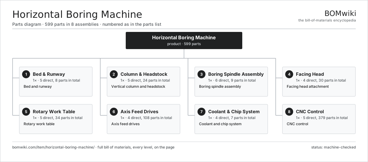
| # | Part | Qty | What it does |
|---|---|---|---|
| 1 | Bed & Runway 5 parts | 1× | Bed and runway |
| 2 | Column & Headstock 5 parts | 1× | Vertical column and headstock |
| 3 | Boring Spindle Assembly 6 parts | 1× | Boring spindle assembly |
| 4 | Facing Head 4 parts | 1× | Facing head attachment |
| 5 | Rotary Work Table 5 parts | 1× | Rotary work table |
| 6 | Axis Feed Drives 4 parts | 1× | Axis feed drives |
| 7 | Coolant & Chip System 4 parts | 1× | Coolant and chip system |
| 8 | CNC Control 5 parts | 1× | CNC control |
3D model
No 3D model yet. Have a CAD file of this? Add a 3D model — STL renders right on this page; STEP, FreeCAD, and OpenSCAD sources are welcome too (openly licensed, like all 3D models on BOMwiki).
Build & assembly graph
expand / collapse · shared sub-assemblies converge · links to related products · est. labourTap an assembly to expand/collapse · tap a part to open it · use “Open page” for any node · drag to pan, scroll to zoom.
Bill of materials for Horizontal Boring Machine
8 top-level lines · 69 rows shown · 599 parts total · indented to 3 levels| # | Item / sub-assembly | Part no. | Qty/assy | Ext. qty | Parts | Type |
|---|---|---|---|---|---|---|
| 1 | Bed & Runway 5 parts | horizontal-boring-machine-bed | 1× | 1 | 8 | assembly |
| 1.1 | Bed Casting | horizontal-boring-machine-bed-casting | 1× | 1 | · | part |
| 1.2 | Column Runway | horizontal-boring-machine-runway | 1× | 1 | · | part |
| 1.3 | Linear Guide Rail | linear-guide | 4× | 4 | · | part |
| 1.4 | Ball Screw | ball-screw | 1× | 1 | · | part |
| 1.5 | Fastener Set | fastener-set | 1× | 1 | · | part |
| 2 | Column & Headstock 5 parts | horizontal-boring-machine-column | 1× | 1 | 24 | assembly |
| 2.1 | Column Casting | horizontal-boring-machine-column-casting | 1× | 1 | · | part |
| 2.2 | Headstock 4 parts | horizontal-boring-machine-headstock | 1× | 1 | 19 | assembly |
| 2.2.1 | Spindle Gearbox 4 parts + deeper › | horizontal-boring-machine-gearbox | 1× | 1 | 12 | assembly |
| 2.2.2 | Spindle Motor | horizontal-boring-machine-spindle-motor | 1× | 1 | · | part |
| 2.2.3 | Helical Gear Pair | gear-pair | 2× | 2 | · | part |
| 2.2.4 | Ball Bearing | ball-bearing | 4× | 4 | · | part |
| 2.3 | Counterweight | horizontal-boring-machine-counterweight | 1× | 1 | · | part |
| 2.4 | Linear Guide Rail | linear-guide | 2× | 2 | · | part |
| 2.5 | Ball Screw | ball-screw | 1× | 1 | · | part |
| 3 | Boring Spindle Assembly 6 parts | horizontal-boring-machine-spindle | 1× | 1 | 9 | assembly |
| 3.1 | Spindle Shaft | horizontal-boring-machine-spindle-shaft | 1× | 1 | · | part |
| 3.2 | Boring Quill | horizontal-boring-machine-quill | 1× | 1 | · | part |
| 3.3 | Quill Bearing | horizontal-boring-machine-quill-bearing | 4× | 4 | · | part |
| 3.4 | Tool Holder | horizontal-boring-machine-toolholder | 1× | 1 | · | part |
| 3.5 | Drawbar | horizontal-boring-machine-drawbar | 1× | 1 | · | part |
| 3.6 | Boring Bar | horizontal-boring-machine-boring-bar | 1× | 1 | · | part |
| 4 | Facing Head 4 parts | horizontal-boring-machine-facing-head | 1× | 1 | 30 | assembly |
| 4.1 | Facing Disc | horizontal-boring-machine-facing-disc | 1× | 1 | · | part |
| 4.2 | Radial Slide | horizontal-boring-machine-radial-slide | 1× | 1 | · | part |
| 4.3 | U-Axis Drive 3 parts | horizontal-boring-machine-u-axis-drive | 1× | 1 | 26 | assembly |
| 4.3.1 | Servo Motor 4 parts + deeper › | servo-motor | 1× | 1 | 24 | assembly |
| 4.3.2 | Ball Screw | ball-screw | 1× | 1 | · | part |
| 4.3.3 | Helical Gear Pair | gear-pair | 1× | 1 | · | part |
| 4.4 | Facing Tool | horizontal-boring-machine-face-tool | 2× | 2 | · | part |
| 5 | Rotary Work Table 5 parts | horizontal-boring-machine-table | 1× | 1 | 34 | assembly |
| 5.1 | Table Top | horizontal-boring-machine-table-top | 1× | 1 | · | part |
| 5.2 | Rotary Bearing | horizontal-boring-machine-rotary-bearing | 1× | 1 | · | part |
| 5.3 | Worm Drive 3 parts | horizontal-boring-machine-worm-drive | 1× | 1 | 27 | assembly |
| 5.3.1 | Servo Motor 4 parts + deeper › | servo-motor | 1× | 1 | 24 | assembly |
| 5.3.2 | Helical Gear Pair | gear-pair | 1× | 1 | · | part |
| 5.3.3 | Ball Bearing | ball-bearing | 2× | 2 | · | part |
| 5.4 | Linear Guide Rail | linear-guide | 4× | 4 | · | part |
| 5.5 | Ball Screw | ball-screw | 1× | 1 | · | part |
| 6 | Axis Feed Drives 4 parts | horizontal-boring-machine-feed-drives | 1× | 1 | 108 | assembly |
| 6.1 | Servo Motor 4 parts | servo-motor | 4× | 4 | 24 | assembly |
| 6.1.1 | Stator Assembly 3 parts + deeper › | stator-assembly | 1× | 4 | 3 | assembly |
| 6.1.2 | Rotor Assembly 4 parts + deeper › | rotor-assembly | 1× | 4 | 19 | assembly |
| 6.1.3 | Encoder | encoder | 1× | 4 | · | part |
| 6.1.4 | Motor Housing | motor-housing | 1× | 4 | · | part |
| 6.2 | Linear Scale | horizontal-boring-machine-scale | 4× | 4 | · | part |
| 6.3 | Axis Reducer | horizontal-boring-machine-gearbox-reducer | 4× | 4 | · | part |
| 6.4 | Way Cover | horizontal-boring-machine-way-cover | 4× | 4 | · | part |
| 7 | Coolant & Chip System 4 parts | horizontal-boring-machine-coolant | 1× | 1 | 7 | assembly |
| 7.1 | Coolant Pump | horizontal-boring-machine-coolant-pump | 1× | 1 | · | part |
| 7.2 | Coolant Tank | horizontal-boring-machine-coolant-tank | 1× | 1 | · | part |
| 7.3 | Chip Conveyor | horizontal-boring-machine-chip-conveyor | 1× | 1 | · | part |
| 7.4 | Coolant Nozzle | horizontal-boring-machine-coolant-nozzle | 4× | 4 | · | part |
| 8 | CNC Control 5 parts | horizontal-boring-machine-control | 1× | 1 | 379 | assembly |
| 8.1 | CNC Computer 3 parts | horizontal-boring-machine-cnc | 1× | 1 | 163 | assembly |
| 8.1.1 | Bare PCB | pcb-bare | 1× | 1 | · | part |
| 8.1.2 | Microcontroller | mcu | 2× | 2 | · | part |
| 8.1.3 | SMD Passive (R/C/L) | smd-passives | 160× | 160 | · | part |
| 8.2 | Drive Cabinet 3 parts | horizontal-boring-machine-drive-cabinet | 1× | 1 | 152 | assembly |
| 8.2.1 | Bare PCB | pcb-bare | 2× | 2 | · | part |
| 8.2.2 | Relay | relay | 10× | 10 | · | part |
| 8.2.3 | SMD Passive (R/C/L) | smd-passives | 140× | 140 | · | part |
| 8.3 | Operator Pendant 3 parts | horizontal-boring-machine-pendant | 1× | 1 | 62 | assembly |
| 8.3.1 | LCD Panel | lcd-panel | 1× | 1 | · | part |
| 8.3.2 | Bare PCB | pcb-bare | 1× | 1 | · | part |
| 8.3.3 | SMD Passive (R/C/L) | smd-passives | 60× | 60 | · | part |
| 8.4 | Power Supply | power-supply | 1× | 1 | · | part |
| 8.5 | Wire Bundle | wire-bundle | 1× | 1 | · | part |
Related products
same domain, ranked by shared parts Bevel Gear Generator
201 parts · shares 6 with this page
Centering and Facing Machine
1,419 parts · shares 6 with this page
Bevel Gear Generator
201 parts · shares 6 with this page
Centering and Facing Machine
1,419 parts · shares 6 with this page
 Creep-Feed Grinder
571 parts · shares 6 with this page
Cut-to-Length Line
500 parts · shares 6 with this page
Double-Disc Grinder
153 parts · shares 6 with this page
Drag Finishing Machine
735 parts · shares 6 with this page
Creep-Feed Grinder
571 parts · shares 6 with this page
Cut-to-Length Line
500 parts · shares 6 with this page
Double-Disc Grinder
153 parts · shares 6 with this page
Drag Finishing Machine
735 parts · shares 6 with this page
Sourcing: possible vendors
Prices, MOQ, and lead times are algorithmic estimates, not quotes, and not claims about these companies. Company mappings are curated by keyword; est. price band $10k–$1M. How estimates work| Vendor | HQ | Specialty | MOQ | Lead time |
|---|---|---|---|---|
|
🇩🇪DMG MORI
dmgmori.com ↗
|
Bielefeld, DE | Machine tools | 5 units | 12–20 wks |
|
🇯🇵Mazak
mazak.com ↗
|
Oguchi, JP | Machine tools | 5 units | 12–20 wks |
| haascnc.com ↗ | Oxnard, US | CNC machine tools | 5 units | 12–20 wks |
|
🇯🇵Okuma
okuma.com ↗
|
Niwa, JP | Machine tools | 5 units | 12–20 wks |
|
🇩🇪Trumpf
trumpf.com ↗
|
Ditzingen, DE | Laser & sheet-metal machines | 5 units | 12–20 wks |
902-word article