Mandrel Tube Bender
ProductOverview
A mandrel tube bender makes tight, smooth bends in tube and pipe by supporting the wall from the inside with a mandrel while the tube is drawn around a bend die. The mandrel keeps the bore from collapsing and the outer wall from wrinkling, so the tube holds its round shape and its cross-section stays nearly constant through the bend. This is the method used wherever a tube must bend on a tight radius without flattening, such as exhaust systems, roll cages, hydraulic lines, and handrails.
The machine is built on a long Machine Bed with a rotary Bend Head at one end and a Feed Carriage that feeds the tube. The bend is shaped by the Clamp and Bend Dies tooling and supported inside by the Mandrel Assembly. A Hydraulic Power Pack supplies clamping force, the CNC Control runs the program, and the Guarding protects the operator.
How it works
This is rotary draw bending. The tube is clamped against the Bend Die by the Clamp Die, and the Bend Arm rotates the bend die through the programmed angle. Because the tube is clamped to the die, it is drawn around the die radius rather than pushed, which gives a controlled, repeatable bend. The Bend Die radius sets the centerline radius of the bend, so a different radius means a different die.
Three dies support the tube during the draw. The Pressure Die backs the outside of the tube and slides forward with it, reacting the outward force. The Wiper Die, a thin pointed tool set just behind the bend tangent on the inside radius, wipes out the wrinkles that would otherwise form where the inner wall is compressed. Inside the tube the mandrel holds the wall against collapse, which is what lets the machine bend on a radius as tight as one tube diameter.
The mandrel
The Mandrel Assembly is what names the machine. A Mandrel Nose plug sized to the tube bore sits exactly at the bend tangent, and behind it a chain of Mandrel Ball segments joined by Ball Link pins flexes around the bend while still pressing the wall outward. The balls let the support follow the curve where a solid plug could not. A Mandrel Rod holds the mandrel at the tangent and takes the heavy pull of the bending tube. After the bend the tube is sprung back slightly and the Mandrel Extractor withdraws the mandrel. Mandrel placement is precise: too far forward and the outer wall thins or splits, too far back and the bend wrinkles or flattens.
Feed and multi-bend work
The Feed Carriage turns the machine from a single-bend tool into a parts machine. Its Tube Collet grips the tube and a Ball Screw driven by the Feed Servo Motor feeds it forward to set the straight length between bends. The Rotation Servo Motor then rotates the collet to set the plane of the next bend. Together with the bend arm these give three CNC axes: feed distance, rotation angle, and bend angle, often written as the DRA values for each bend. A Carriage Encoder confirms each move. With these three axes the machine can bend a complex exhaust or frame from a single straight tube without the operator touching it between bends.
Hydraulics and control
The Hydraulic Power Pack supplies clamping. Its Hydraulic Pump feeds the clamp, pressure die, and extractor cylinders through a Valve Manifold that sequences them, with Pressure Sensor feedback. The CNC Control runs everything: a CNC Unit executes the part program while one Servo Drive per axis closes its loop, and the Bend Encoder and carriage encoders report position. The operator works through an LCD Panel. The control also adds spring-back compensation, over-bending each bend slightly so it relaxes to the right angle. Relay outputs switch heavier loads and signals run over a Wire Bundle and Connector set.
Materials and use
Mandrel bending suits steel, stainless, aluminium, and titanium tube, and is chosen whenever flow, appearance, or fit demands a clean cross-section through the bend. An automotive exhaust bent on a mandrel keeps its full bore so it does not choke gas flow, where a press bend would flatten and restrict it. Roll cages, aircraft tubing, hydraulic and fuel lines, furniture frames, and architectural rails all use it for the same reason. The tooling is dedicated: each tube size and bend radius needs its own die set and mandrel, so the machine is set up for a tube family and run in volume, while the CNC axes let one setup produce many different bent shapes by program alone.
Mandrel Tube Bender parts and their functions
8 top-level parts · 116 parts in total · full bill of materials below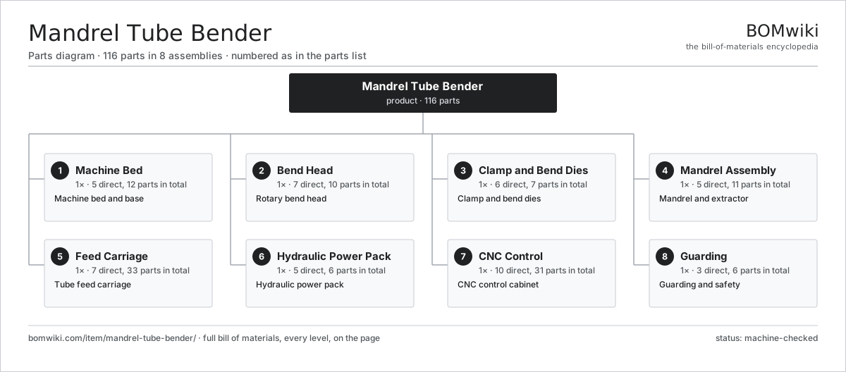
| # | Part | Qty | What it does |
|---|---|---|---|
| 1 | Machine Bed 5 parts | 1× | Machine bed and base |
| 2 | Bend Head 7 parts | 1× | Rotary bend head |
| 3 | Clamp and Bend Dies 6 parts | 1× | Clamp and bend dies |
| 4 | Mandrel Assembly 5 parts | 1× | Mandrel and extractor |
| 5 | Feed Carriage 7 parts | 1× | Tube feed carriage |
| 6 | Hydraulic Power Pack 5 parts | 1× | Hydraulic power pack |
| 7 | CNC Control 10 parts | 1× | CNC control cabinet |
| 8 | Guarding 3 parts | 1× | Guarding and safety |
3D model
No 3D model yet. Have a CAD file of this? Add a 3D model — STL renders right on this page; STEP, FreeCAD, and OpenSCAD sources are welcome too (openly licensed, like all 3D models on BOMwiki).
Build & assembly graph
expand / collapse · shared sub-assemblies converge · links to related products · est. labourTap an assembly to expand/collapse · tap a part to open it · use “Open page” for any node · drag to pan, scroll to zoom.
Bill of materials for Mandrel Tube Bender
8 top-level lines · 60 rows shown · 116 parts total · indented to 3 levels| # | Item / sub-assembly | Part no. | Qty/assy | Ext. qty | Parts | Type |
|---|---|---|---|---|---|---|
| 1 | Machine Bed 5 parts | mandrel-tube-bender-bed | 1× | 1 | 12 | assembly |
| 1.1 | Base Frame | mandrel-tube-bender-base-frame | 1× | 1 | · | part |
| 1.2 | Linear Guide Rail | linear-guide | 2× | 2 | · | part |
| 1.3 | Way Cover | mandrel-tube-bender-way-cover | 2× | 2 | · | part |
| 1.4 | Leveling Pad | mandrel-tube-bender-leveling-pad | 6× | 6 | · | part |
| 1.5 | Fastener Set | fastener-set | 1× | 1 | · | part |
| 2 | Bend Head 7 parts | mandrel-tube-bender-bend-head | 1× | 1 | 10 | assembly |
| 2.1 | Bend Arm | mandrel-tube-bender-bend-arm | 1× | 1 | · | part |
| 2.2 | Bend Servo Motor | mandrel-tube-bender-bend-servo | 1× | 1 | · | part |
| 2.3 | Gearbox Housing | gearbox-housing | 1× | 1 | · | part |
| 2.4 | Helical Gear Pair | gear-pair | 2× | 2 | · | part |
| 2.5 | Bend Encoder | mandrel-tube-bender-bend-encoder | 1× | 1 | · | part |
| 2.6 | Ball Bearing | ball-bearing | 3× | 3 | · | part |
| 2.7 | Oil Seal | oil-seal | 1× | 1 | · | part |
| 3 | Clamp and Bend Dies 6 parts | mandrel-tube-bender-clamp-die | 1× | 1 | 7 | assembly |
| 3.1 | Bend Die | mandrel-tube-bender-bend-die | 1× | 1 | · | part |
| 3.2 | Clamp Die | mandrel-tube-bender-clamp-block | 1× | 1 | · | part |
| 3.3 | Pressure Die | mandrel-tube-bender-pressure-die | 1× | 1 | · | part |
| 3.4 | Wiper Die | mandrel-tube-bender-wiper-die | 1× | 1 | · | part |
| 3.5 | Clamp Cylinder | mandrel-tube-bender-clamp-cylinder | 2× | 2 | · | part |
| 3.6 | O-Ring Set | oring-set | 1× | 1 | · | part |
| 4 | Mandrel Assembly 5 parts | mandrel-tube-bender-mandrel-assembly | 1× | 1 | 11 | assembly |
| 4.1 | Mandrel Nose | mandrel-tube-bender-mandrel-nose | 1× | 1 | · | part |
| 4.2 | Mandrel Ball | mandrel-tube-bender-mandrel-ball | 4× | 4 | · | part |
| 4.3 | Mandrel Rod | mandrel-tube-bender-mandrel-rod | 1× | 1 | · | part |
| 4.4 | Mandrel Extractor | mandrel-tube-bender-extractor | 1× | 1 | · | part |
| 4.5 | Ball Link | mandrel-tube-bender-link | 4× | 4 | · | part |
| 5 | Feed Carriage 7 parts | mandrel-tube-bender-carriage | 1× | 1 | 33 | assembly |
| 5.1 | Tube Collet | mandrel-tube-bender-collet | 1× | 1 | · | part |
| 5.2 | Feed Servo Motor | mandrel-tube-bender-feed-servo | 1× | 1 | · | part |
| 5.3 | Rotation Servo Motor | mandrel-tube-bender-rotation-servo | 1× | 1 | · | part |
| 5.4 | Ball Screw | ball-screw | 1× | 1 | · | part |
| 5.5 | Servo Motor 4 parts | servo-motor | 1× | 1 | 24 | assembly |
| 5.5.1 | Stator Assembly 3 parts + deeper › | stator-assembly | 1× | 1 | 3 | assembly |
| 5.5.2 | Rotor Assembly 4 parts + deeper › | rotor-assembly | 1× | 1 | 19 | assembly |
| 5.5.3 | Encoder | encoder | 1× | 1 | · | part |
| 5.5.4 | Motor Housing | motor-housing | 1× | 1 | · | part |
| 5.6 | Carriage Encoder | mandrel-tube-bender-carriage-encoder | 2× | 2 | · | part |
| 5.7 | Ball Bearing | ball-bearing | 3× | 3 | · | part |
| 6 | Hydraulic Power Pack 5 parts | mandrel-tube-bender-hydraulic-unit | 1× | 1 | 6 | assembly |
| 6.1 | Hydraulic Pump | mandrel-tube-bender-hydraulic-pump | 1× | 1 | · | part |
| 6.2 | Hydraulic Tank | mandrel-tube-bender-hydraulic-tank | 1× | 1 | · | part |
| 6.3 | Valve Manifold | mandrel-tube-bender-valve-block | 1× | 1 | · | part |
| 6.4 | Pressure Sensor | pressure-sensor | 2× | 2 | · | part |
| 6.5 | O-Ring Set | oring-set | 1× | 1 | · | part |
| 7 | CNC Control 10 parts | mandrel-tube-bender-cnc-control | 1× | 1 | 31 | assembly |
| 7.1 | CNC Unit | mandrel-tube-bender-cnc-unit | 1× | 1 | · | part |
| 7.2 | Servo Drive | mandrel-tube-bender-servo-drive | 4× | 4 | · | part |
| 7.3 | LCD Panel | lcd-panel | 1× | 1 | · | part |
| 7.4 | Power Supply | power-supply | 1× | 1 | · | part |
| 7.5 | Bare PCB | pcb-bare | 1× | 1 | · | part |
| 7.6 | Microcontroller | mcu | 1× | 1 | · | part |
| 7.7 | SMD Passive (R/C/L) | smd-passives | 1× | 1 | · | part |
| 7.8 | Relay | relay | 6× | 6 | · | part |
| 7.9 | Wire Bundle | wire-bundle | 1× | 1 | · | part |
| 7.10 | Connector | connector | 14× | 14 | · | part |
| 8 | Guarding 3 parts | mandrel-tube-bender-guard | 1× | 1 | 6 | assembly |
| 8.1 | Sheet Metal Panel | sheet-panel | 3× | 3 | · | part |
| 8.2 | Light Curtain | mandrel-tube-bender-light-curtain | 1× | 1 | · | part |
| 8.3 | Emergency Stop | mandrel-tube-bender-estop | 2× | 2 | · | part |
Related products
same domain, ranked by shared parts Creep-Feed Grinder
571 parts · shares 8 with this page
Cut-to-Length Line
500 parts · shares 8 with this page
Drag Finishing Machine
735 parts · shares 8 with this page
Creep-Feed Grinder
571 parts · shares 8 with this page
Cut-to-Length Line
500 parts · shares 8 with this page
Drag Finishing Machine
735 parts · shares 8 with this page
 Flow Forming Machine
272 parts · shares 8 with this page
Plate Shear
679 parts · shares 8 with this page
Flow Forming Machine
272 parts · shares 8 with this page
Plate Shear
679 parts · shares 8 with this page
Sourcing: possible vendors
Prices, MOQ, and lead times are algorithmic estimates, not quotes, and not claims about these companies. Company mappings are curated by keyword; est. price band $10k–$1M. How estimates work| Vendor | HQ | Specialty | MOQ | Lead time |
|---|---|---|---|---|
|
🇩🇪DMG MORI
dmgmori.com ↗
|
Bielefeld, DE | Machine tools | 5 units | 12–20 wks |
|
🇯🇵Mazak
mazak.com ↗
|
Oguchi, JP | Machine tools | 5 units | 12–20 wks |
| haascnc.com ↗ | Oxnard, US | CNC machine tools | 5 units | 12–20 wks |
|
🇯🇵Okuma
okuma.com ↗
|
Niwa, JP | Machine tools | 5 units | 12–20 wks |
|
🇩🇪Trumpf
trumpf.com ↗
|
Ditzingen, DE | Laser & sheet-metal machines | 5 units | 12–20 wks |
854-word article