Angle Roll Bender
ProductOverview
An angle roll bender curves bar and angle stock into rings, hoops, arcs, and scrolls by passing it through three rolls arranged in a pyramid. Two lower rolls drive the stock forward while a single upper roll presses down between them, bending the bar to a radius set by how far the upper roll is lowered. It is the simplest of the roll-bending machines and the most common in general fabrication, because it handles flat bar, round bar, square bar, and angle with a quick change of roll dies.
The machine is built on a heavy Main Frame that holds the three-roll Pyramid Roll Set set. A Roll Drive turns the lower rolls, the Pinch Position Axis moves the upper pinch roll, and a Hydraulic Power Pack supplies the force. The NC Control sets the radius, the Roll Tooling suits each stock shape, and the Guarding protects the operator.
How it works
The bar is fed into the three rolls so it rests on the two Lower Roll dies and under the Upper Pinch Roll. The Pinch Cylinder lowers the upper roll, pressing the bar down between the lower pair. The two lower rolls are driven, so they grip the bar and feed it forward. As each length passes under the lowered upper roll it is bent past its yield point and takes a permanent curve. The lower the upper roll, the tighter the radius.
Tight radii are reached in steps. The operator lowers the upper roll a little, runs the bar back and forth using the Foot Pedal, lowers again, and repeats until the radius is met. Pressing too hard in one pass would kink the bar or overload the rolls. A full ring is made by feeding the bar around until the ends meet, then trimming and welding. Scrolls and tapered curves are made by changing the pinch depth while feeding. The Position Encoder on the upper roll lets the operator return to a known pinch position so the same radius repeats from part to part.
The leading and trailing ends of the bar stay slightly straight because they pass the rolls before bending starts. For rings this flat is removed when the ends are trimmed to length; for arcs it is either pre-bent in a press or cut off.
Subsystems
The Main Frame carries the bending reaction. Its welded Frame Housing holds the three Roll Shaft journals in Bearing Block supports and must stay rigid so the rolls keep their pyramid spacing under load. The two lower rolls sit in fixed corners; only the upper roll moves.
The Roll Drive supplies torque through a Gearbox Housing with Helical Gear Pair reduction, splitting drive to both lower rolls through Roll Coupling connections so they feed evenly. A Drive Motor turns the rolls slowly, since bar bending needs torque rather than speed.
The Pinch Position Axis sets the radius. The Pinch Cylinder drives the upper roll bearing block up and down on Slide Guide ways riding Linear Guide Rail rails, and the encoder reports its height. Because the radius depends entirely on this position, the slide must hold the roll steady against the upward force of the bending bar.
Hydraulics and control
The Hydraulic Power Pack supplies the pinch force. Its Hydraulic Pump feeds the pinch cylinder and drive motor through a Valve Manifold, with Pressure Sensor feedback. The NC Control reads the upper-roll encoder and meters the cylinder to hold the roll at its target height. A Control Unit keeps pinch position and feed repeatable, and the operator sets values through an LCD Panel. Feed is hand-paced with the foot pedal so the operator can guide the bar and watch the curve form. Relay outputs switch the heavier loads and signals run over a Wire Bundle and Connector set.
Tooling
The Roll Tooling adapts the machine to each stock shape. An Flat-Bar Roll Die bends flat bar on edge or on face, an Angle Roll Die supports an angle leg so the section does not fold, and an Round-Bar Roll Die is grooved so round bar seats and does not slip sideways. A Spacer Ring sets the axial position of each die on the shaft. Matching the die to the stock is what keeps the section in shape: an unsupported angle leg would buckle and a round bar would wander without a groove. Dies are hardened tool steel and swap quickly on the splined shafts.
Variants and use
Angle roll benders range from small manual machines that roll light bar for ornamental ironwork to powered NC machines that bend heavy angle and bar for tank rings, ducting hoops, frames, and architectural curves. The pyramid layout, with two fixed lower rolls and one moving upper roll, keeps them simple, robust, and quick to set up, which is why they are a staple in ornamental, structural, and general fabrication shops. They overlap with section bending machines, but the pyramid bender is favoured for bar and light angle where a fast die change and pedal-paced feed suit short-run and one-off work.
Angle Roll Bender parts and their functions
8 top-level parts · 100 parts in total · full bill of materials below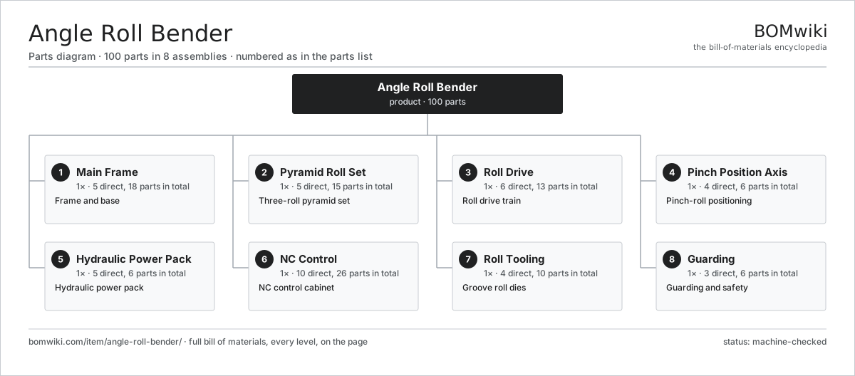
| # | Part | Qty | What it does |
|---|---|---|---|
| 1 | Main Frame 5 parts | 1× | Frame and base |
| 2 | Pyramid Roll Set 5 parts | 1× | Three-roll pyramid set |
| 3 | Roll Drive 6 parts | 1× | Roll drive train |
| 4 | Pinch Position Axis 4 parts | 1× | Pinch-roll positioning |
| 5 | Hydraulic Power Pack 5 parts | 1× | Hydraulic power pack |
| 6 | NC Control 10 parts | 1× | NC control cabinet |
| 7 | Roll Tooling 4 parts | 1× | Groove roll dies |
| 8 | Guarding 3 parts | 1× | Guarding and safety |
3D model
No 3D model yet. Have a CAD file of this? Add a 3D model — STL renders right on this page; STEP, FreeCAD, and OpenSCAD sources are welcome too (openly licensed, like all 3D models on BOMwiki).
Build & assembly graph
expand / collapse · shared sub-assemblies converge · links to related products · est. labourTap an assembly to expand/collapse · tap a part to open it · use “Open page” for any node · drag to pan, scroll to zoom.
Bill of materials for Angle Roll Bender
8 top-level lines · 50 rows shown · 100 parts total · indented to 3 levels| # | Item / sub-assembly | Part no. | Qty/assy | Ext. qty | Parts | Type |
|---|---|---|---|---|---|---|
| 1 | Main Frame 5 parts | angle-roll-bender-frame | 1× | 1 | 18 | assembly |
| 1.1 | Frame Housing | angle-roll-bender-housing | 1× | 1 | · | part |
| 1.2 | Bearing Block | angle-roll-bender-bearing-block | 6× | 6 | · | part |
| 1.3 | Ball Bearing | ball-bearing | 6× | 6 | · | part |
| 1.4 | Leveling Pad | angle-roll-bender-leveling-pad | 4× | 4 | · | part |
| 1.5 | Fastener Set | fastener-set | 1× | 1 | · | part |
| 2 | Pyramid Roll Set 5 parts | angle-roll-bender-pyramid-rolls | 1× | 1 | 15 | assembly |
| 2.1 | Lower Roll | angle-roll-bender-lower-roll | 2× | 2 | · | part |
| 2.2 | Upper Pinch Roll | angle-roll-bender-upper-roll | 1× | 1 | · | part |
| 2.3 | Roll Shaft | angle-roll-bender-roll-shaft | 3× | 3 | · | part |
| 2.4 | Ball Bearing | ball-bearing | 6× | 6 | · | part |
| 2.5 | Oil Seal | oil-seal | 3× | 3 | · | part |
| 3 | Roll Drive 6 parts | angle-roll-bender-drive | 1× | 1 | 13 | assembly |
| 3.1 | Drive Motor | angle-roll-bender-drive-motor | 1× | 1 | · | part |
| 3.2 | Gearbox Housing | gearbox-housing | 1× | 1 | · | part |
| 3.3 | Helical Gear Pair | gear-pair | 3× | 3 | · | part |
| 3.4 | Roll Coupling | angle-roll-bender-coupling | 2× | 2 | · | part |
| 3.5 | Ball Bearing | ball-bearing | 4× | 4 | · | part |
| 3.6 | Oil Seal | oil-seal | 2× | 2 | · | part |
| 4 | Pinch Position Axis 4 parts | angle-roll-bender-position-axis | 1× | 1 | 6 | assembly |
| 4.1 | Pinch Cylinder | angle-roll-bender-pinch-cylinder | 1× | 1 | · | part |
| 4.2 | Position Encoder | angle-roll-bender-position-encoder | 1× | 1 | · | part |
| 4.3 | Slide Guide | angle-roll-bender-slide-guide | 2× | 2 | · | part |
| 4.4 | Linear Guide Rail | linear-guide | 2× | 2 | · | part |
| 5 | Hydraulic Power Pack 5 parts | angle-roll-bender-hydraulic-unit | 1× | 1 | 6 | assembly |
| 5.1 | Hydraulic Pump | angle-roll-bender-hydraulic-pump | 1× | 1 | · | part |
| 5.2 | Hydraulic Tank | angle-roll-bender-hydraulic-tank | 1× | 1 | · | part |
| 5.3 | Valve Manifold | angle-roll-bender-valve-block | 1× | 1 | · | part |
| 5.4 | Pressure Sensor | pressure-sensor | 2× | 2 | · | part |
| 5.5 | O-Ring Set | oring-set | 1× | 1 | · | part |
| 6 | NC Control 10 parts | angle-roll-bender-control | 1× | 1 | 26 | assembly |
| 6.1 | Control Unit | angle-roll-bender-control-unit | 1× | 1 | · | part |
| 6.2 | LCD Panel | lcd-panel | 1× | 1 | · | part |
| 6.3 | Power Supply | power-supply | 1× | 1 | · | part |
| 6.4 | Bare PCB | pcb-bare | 1× | 1 | · | part |
| 6.5 | Microcontroller | mcu | 1× | 1 | · | part |
| 6.6 | SMD Passive (R/C/L) | smd-passives | 1× | 1 | · | part |
| 6.7 | Relay | relay | 6× | 6 | · | part |
| 6.8 | Foot Pedal | angle-roll-bender-foot-pedal | 1× | 1 | · | part |
| 6.9 | Wire Bundle | wire-bundle | 1× | 1 | · | part |
| 6.10 | Connector | connector | 12× | 12 | · | part |
| 7 | Roll Tooling 4 parts | angle-roll-bender-tooling | 1× | 1 | 10 | assembly |
| 7.1 | Flat-Bar Roll Die | angle-roll-bender-flat-die | 2× | 2 | · | part |
| 7.2 | Angle Roll Die | angle-roll-bender-angle-die | 2× | 2 | · | part |
| 7.3 | Round-Bar Roll Die | angle-roll-bender-round-die | 2× | 2 | · | part |
| 7.4 | Spacer Ring | angle-roll-bender-spacer | 4× | 4 | · | part |
| 8 | Guarding 3 parts | angle-roll-bender-guard | 1× | 1 | 6 | assembly |
| 8.1 | Sheet Metal Panel | sheet-panel | 3× | 3 | · | part |
| 8.2 | Emergency Stop | angle-roll-bender-estop | 2× | 2 | · | part |
| 8.3 | Trip Bar | angle-roll-bender-trip-bar | 1× | 1 | · | part |
Related products
same domain, ranked by shared parts Creep-Feed Grinder
571 parts · shares 6 with this page
Cut-to-Length Line
500 parts · shares 6 with this page
Drag Finishing Machine
735 parts · shares 6 with this page
Creep-Feed Grinder
571 parts · shares 6 with this page
Cut-to-Length Line
500 parts · shares 6 with this page
Drag Finishing Machine
735 parts · shares 6 with this page
 Flow Forming Machine
272 parts · shares 6 with this page
Flow Forming Machine
272 parts · shares 6 with this page
Sourcing: possible vendors
Prices, MOQ, and lead times are algorithmic estimates, not quotes, and not claims about these companies. Company mappings are curated by keyword; est. price band $10k–$1M. How estimates work| Vendor | HQ | Specialty | MOQ | Lead time |
|---|---|---|---|---|
|
🇩🇪DMG MORI
dmgmori.com ↗
|
Bielefeld, DE | Machine tools | 5 units | 12–20 wks |
|
🇯🇵Mazak
mazak.com ↗
|
Oguchi, JP | Machine tools | 5 units | 12–20 wks |
| haascnc.com ↗ | Oxnard, US | CNC machine tools | 5 units | 12–20 wks |
|
🇯🇵Okuma
okuma.com ↗
|
Niwa, JP | Machine tools | 5 units | 12–20 wks |
|
🇩🇪Trumpf
trumpf.com ↗
|
Ditzingen, DE | Laser & sheet-metal machines | 5 units | 12–20 wks |
926-word article