Flow Forming Machine
ProductOverview
A flow forming machine is a cold rotary forming machine that turns a short, thick-walled tube preform into a long, thin-walled cylinder without removing any material. The preform is clamped onto a rotating mandrel, and a set of forming rollers presses into the spinning wall and feeds along its length. The metal under each roller is squeezed thinner and pushed forward, so the wall flows axially and the tube grows much longer than it started. Because the process works the metal in the cold state, the grain is refined and the finished part is stronger than the starting blank.
The machine is built around a rigid Machine Bed that locates the rotating Headstock, the three Roller Carriage slides, and a hydraulic Tailstock. A Hydraulic Power Pack supplies clamping pressure, the CNC Control coordinates every motion, and the Coolant System manages the heat the forming generates. The whole working zone sits behind sealed Guarding panels.
How it works
The cycle begins by loading a tube preform over the Forming Mandrel and clamping it with the Preform Chuck. The Clamp Cylinder in the tailstock drives a Live Center against the free end so the preform cannot slip. The Spindle Motor then spins the Main Spindle, mandrel, and workpiece together, typically at a few hundred rpm.
With the work turning, each Roller Carriage advances its Forming Roller radially into the wall using a Radial Slide, setting the depth that fixes final wall thickness. The Axial Slide then feeds the roller along the mandrel. The metal cannot escape inward because the mandrel is solid, so it is displaced forward, lengthening the tube. The three rollers are staggered both around the circumference and along the axis so that each one takes part of the reduction, balancing the radial load on the mandrel and giving a smooth final surface. A Forming Load Cell on each carriage reports the forming force back to the control.
Flow forming runs in two directions. In forward flow forming the rollers move away from the chuck and the metal flows ahead of them. In reverse flow forming the rollers move toward the chuck and the metal flows backward, opposite to the roller travel, which suits closed-end parts. The choice depends on part geometry and on how the wall length is anchored.
Subsystems
The Headstock is the most heavily loaded subsystem. Its Main Spindle runs in large preloaded Ball Bearing sets and is driven through a Gearbox Housing holding speed-reduction Helical Gear Pair sets, because the process needs high torque at moderate speed rather than high speed. The mandrel is the master tool: its diameter, taper, and surface finish are reproduced on the inside of every part, so it is made from hardened tool steel and reground when worn.
Each Roller Carriage is effectively a small two-axis CNC slide. A Ball Screw driven by a Servo Motor sets radial depth, and a second ball-screw and servo set axial feed, both running on Linear Guide Rail rails. Matching the feed of all three carriages to the spindle speed is what produces a straight, concentric tube; any mismatch shows up as a spiral mark or a thickness variation.
The Hydraulic Power Pack is dedicated to clamping. Its Hydraulic Pump holds pressure through an Hydraulic Accumulator, and a Valve Manifold regulates the clamp cylinder so the preform stays seated under heavy forming loads. Pressure Sensor feedback lets the control confirm clamp force before the rollers engage.
Control and sensing
The CNC Control runs seven or more coordinated axes: the spindle, three radial slides, and three axial slides. A CNC Unit executes the part program while one Servo Drive per axis closes the position and torque loops. Operators set up and watch the cycle through an LCD Panel. Because forming force is the key process variable, the control reads the carriage load cells continuously and can back off a roller or trim feed if force climbs toward the mandrel or machine limit. Logic-level signals are distributed over a Wire Bundle and field Connector set, with Relay outputs for the heavier interlocked loads.
Materials and tooling
Flow forming is used on metals that work-harden in a controlled way: low-alloy and stainless steels, titanium, and aluminium alloys. The starting preform is usually a forged or machined ring or a deep-drawn cup. Tooling life centers on the mandrel and the Forming Roller profiles, both made from H13 or D2 tool steel and finished to a fine surface so it transfers cleanly to the part. The Coolant System floods the contact zone through aimed Coolant Nozzle jets to control temperature and reduce roller wear, while a Chip Conveyor clears any trimmed flash.
Variants and use
Machines range from small units that form drive shafts and cylinder liners to large vertical and horizontal machines that produce rocket motor cases, gas cylinders, and pressure vessels several metres long. Some combine flow forming with shear forming on the same bed so a single setup can both spin a flange and thin a barrel. The defining benefits are tight wall tolerance, a strong work-hardened structure, and very little scrap, which is why the process is common in aerospace, defence, and high-pressure gas storage. Reductions of seventy percent or more in a single pass are routine on ductile alloys, and the finished bore typically holds the mandrel diameter within a few hundredths of a millimetre.
Flow Forming Machine parts and their functions
8 top-level parts · 272 parts in total · full bill of materials below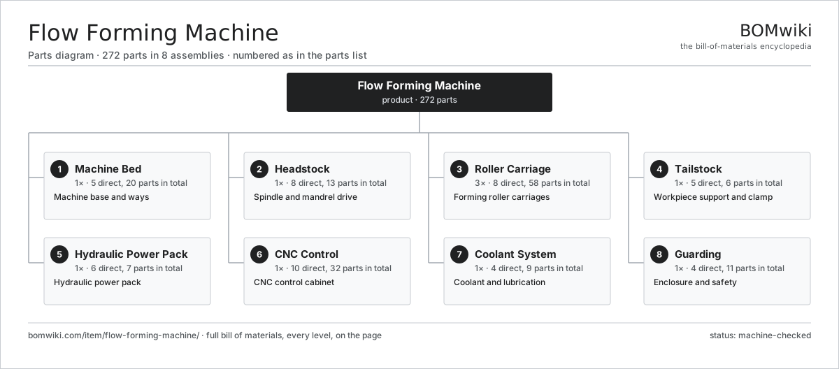
| # | Part | Qty | What it does |
|---|---|---|---|
| 1 | Machine Bed 5 parts | 1× | Machine base and ways |
| 2 | Headstock 8 parts | 1× | Spindle and mandrel drive |
| 3 | Roller Carriage 8 parts | 3× | Forming roller carriages |
| 4 | Tailstock 5 parts | 1× | Workpiece support and clamp |
| 5 | Hydraulic Power Pack 6 parts | 1× | Hydraulic power pack |
| 6 | CNC Control 10 parts | 1× | CNC control cabinet |
| 7 | Coolant System 4 parts | 1× | Coolant and lubrication |
| 8 | Guarding 4 parts | 1× | Enclosure and safety |
3D model
No 3D model yet. Have a CAD file of this? Add a 3D model — STL renders right on this page; STEP, FreeCAD, and OpenSCAD sources are welcome too (openly licensed, like all 3D models on BOMwiki).
Build & assembly graph
expand / collapse · shared sub-assemblies converge · links to related products · est. labourTap an assembly to expand/collapse · tap a part to open it · use “Open page” for any node · drag to pan, scroll to zoom.
Bill of materials for Flow Forming Machine
8 top-level lines · 62 rows shown · 272 parts total · indented to 3 levels| # | Item / sub-assembly | Part no. | Qty/assy | Ext. qty | Parts | Type |
|---|---|---|---|---|---|---|
| 1 | Machine Bed 5 parts | flow-forming-machine-bed | 1× | 1 | 20 | assembly |
| 1.1 | Base Casting | flow-forming-machine-base-casting | 1× | 1 | · | part |
| 1.2 | Linear Guide Rail | linear-guide | 6× | 6 | · | part |
| 1.3 | Way Cover | flow-forming-machine-way-cover | 4× | 4 | · | part |
| 1.4 | Leveling Pad | flow-forming-machine-leveling-pad | 8× | 8 | · | part |
| 1.5 | Fastener Set | fastener-set | 1× | 1 | · | part |
| 2 | Headstock 8 parts | flow-forming-machine-headstock | 1× | 1 | 13 | assembly |
| 2.1 | Main Spindle | flow-forming-machine-spindle | 1× | 1 | · | part |
| 2.2 | Spindle Motor | flow-forming-machine-spindle-motor | 1× | 1 | · | part |
| 2.3 | Gearbox Housing | gearbox-housing | 1× | 1 | · | part |
| 2.4 | Helical Gear Pair | gear-pair | 2× | 2 | · | part |
| 2.5 | Forming Mandrel | flow-forming-machine-mandrel | 1× | 1 | · | part |
| 2.6 | Preform Chuck | flow-forming-machine-chuck | 1× | 1 | · | part |
| 2.7 | Ball Bearing | ball-bearing | 4× | 4 | · | part |
| 2.8 | Oil Seal | oil-seal | 2× | 2 | · | part |
| 3 | Roller Carriage 8 parts | flow-forming-machine-roller-carriage | 3× | 3 | 58 | assembly |
| 3.1 | Forming Roller | flow-forming-machine-forming-roller | 1× | 3 | · | part |
| 3.2 | Roller Spindle | flow-forming-machine-roller-spindle | 1× | 3 | · | part |
| 3.3 | Radial Slide | flow-forming-machine-radial-slide | 1× | 3 | · | part |
| 3.4 | Axial Slide | flow-forming-machine-axial-slide | 1× | 3 | · | part |
| 3.5 | Ball Screw | ball-screw | 2× | 6 | · | part |
| 3.6 | Servo Motor 4 parts | servo-motor | 2× | 6 | 24 | assembly |
| 3.6.1 | Stator Assembly 3 parts + deeper › | stator-assembly | 1× | 6 | 3 | assembly |
| 3.6.2 | Rotor Assembly 4 parts + deeper › | rotor-assembly | 1× | 6 | 19 | assembly |
| 3.6.3 | Encoder | encoder | 1× | 6 | · | part |
| 3.6.4 | Motor Housing | motor-housing | 1× | 6 | · | part |
| 3.7 | Forming Load Cell | flow-forming-machine-load-cell | 1× | 3 | · | part |
| 3.8 | Ball Bearing | ball-bearing | 3× | 9 | · | part |
| 4 | Tailstock 5 parts | flow-forming-machine-tailstock | 1× | 1 | 6 | assembly |
| 4.1 | Tailstock Body | flow-forming-machine-tailstock-body | 1× | 1 | · | part |
| 4.2 | Clamp Cylinder | flow-forming-machine-clamp-cylinder | 1× | 1 | · | part |
| 4.3 | Live Center | flow-forming-machine-live-center | 1× | 1 | · | part |
| 4.4 | Ball Bearing | ball-bearing | 2× | 2 | · | part |
| 4.5 | O-Ring Set | oring-set | 1× | 1 | · | part |
| 5 | Hydraulic Power Pack 6 parts | flow-forming-machine-hydraulic-unit | 1× | 1 | 7 | assembly |
| 5.1 | Hydraulic Pump | flow-forming-machine-hydraulic-pump | 1× | 1 | · | part |
| 5.2 | Hydraulic Tank | flow-forming-machine-hydraulic-tank | 1× | 1 | · | part |
| 5.3 | Valve Manifold | flow-forming-machine-valve-block | 1× | 1 | · | part |
| 5.4 | Hydraulic Accumulator | flow-forming-machine-accumulator | 1× | 1 | · | part |
| 5.5 | Pressure Sensor | pressure-sensor | 2× | 2 | · | part |
| 5.6 | O-Ring Set | oring-set | 1× | 1 | · | part |
| 6 | CNC Control 10 parts | flow-forming-machine-cnc-control | 1× | 1 | 32 | assembly |
| 6.1 | CNC Unit | flow-forming-machine-cnc-unit | 1× | 1 | · | part |
| 6.2 | Servo Drive | flow-forming-machine-servo-drive | 7× | 7 | · | part |
| 6.3 | LCD Panel | lcd-panel | 1× | 1 | · | part |
| 6.4 | Power Supply | power-supply | 1× | 1 | · | part |
| 6.5 | Bare PCB | pcb-bare | 1× | 1 | · | part |
| 6.6 | Microcontroller | mcu | 1× | 1 | · | part |
| 6.7 | SMD Passive (R/C/L) | smd-passives | 1× | 1 | · | part |
| 6.8 | Relay | relay | 6× | 6 | · | part |
| 6.9 | Wire Bundle | wire-bundle | 1× | 1 | · | part |
| 6.10 | Connector | connector | 12× | 12 | · | part |
| 7 | Coolant System 4 parts | flow-forming-machine-coolant-system | 1× | 1 | 9 | assembly |
| 7.1 | Coolant Pump | flow-forming-machine-coolant-pump | 1× | 1 | · | part |
| 7.2 | Coolant Tank | flow-forming-machine-coolant-tank | 1× | 1 | · | part |
| 7.3 | Coolant Nozzle | flow-forming-machine-coolant-nozzle | 6× | 6 | · | part |
| 7.4 | Chip Conveyor | flow-forming-machine-chip-conveyor | 1× | 1 | · | part |
| 8 | Guarding 4 parts | flow-forming-machine-guard | 1× | 1 | 11 | assembly |
| 8.1 | Sheet Metal Panel | sheet-panel | 6× | 6 | · | part |
| 8.2 | Access Door | flow-forming-machine-access-door | 2× | 2 | · | part |
| 8.3 | Viewing Window | flow-forming-machine-window | 1× | 1 | · | part |
| 8.4 | Door Interlock | flow-forming-machine-door-interlock | 2× | 2 | · | part |
Related products
same domain, ranked by shared parts Creep-Feed Grinder
571 parts · shares 8 with this page
Cut-to-Length Line
500 parts · shares 8 with this page
Drag Finishing Machine
735 parts · shares 8 with this page
Mandrel Tube Bender
116 parts · shares 8 with this page
Plate Shear
679 parts · shares 8 with this page
Creep-Feed Grinder
571 parts · shares 8 with this page
Cut-to-Length Line
500 parts · shares 8 with this page
Drag Finishing Machine
735 parts · shares 8 with this page
Mandrel Tube Bender
116 parts · shares 8 with this page
Plate Shear
679 parts · shares 8 with this page
Sourcing: possible vendors
Prices, MOQ, and lead times are algorithmic estimates, not quotes, and not claims about these companies. Company mappings are curated by keyword; est. price band $10k–$1M. How estimates work| Vendor | HQ | Specialty | MOQ | Lead time |
|---|---|---|---|---|
|
🇩🇪DMG MORI
dmgmori.com ↗
|
Bielefeld, DE | Machine tools | 5 units | 12–20 wks |
|
🇯🇵Mazak
mazak.com ↗
|
Oguchi, JP | Machine tools | 5 units | 12–20 wks |
| haascnc.com ↗ | Oxnard, US | CNC machine tools | 5 units | 12–20 wks |
|
🇯🇵Okuma
okuma.com ↗
|
Niwa, JP | Machine tools | 5 units | 12–20 wks |
|
🇩🇪Trumpf
trumpf.com ↗
|
Ditzingen, DE | Laser & sheet-metal machines | 5 units | 12–20 wks |
991-word article