Railway Wheel Lathe
ProductOverview
A railway wheel lathe restores the worn rolling profile of a railway wheelset by machining the tread and flange back to a defined contour. Wheels lose material and develop hollow tread wear, flange thinning, and surface defects such as flats and shelling. Rather than scrap the wheel, an operator clamps the wheelset, the lathe turns away a thin layer, typically 1 to 5 mm on diameter, and recreates the standard profile. The Machine Bed carries two opposing headstocks so both wheels of a wheelset are driven and cut in one setup, which keeps the two wheels equal in diameter to within tenths of a millimetre.
Two broad layouts exist. An above-floor lathe receives a wheelset that has been removed from the bogie and lifted onto the machine. An underfloor lathe sits in a pit beneath the track so a whole vehicle can be driven over it and reprofiled without removing the wheelsets. The mechanical building blocks are similar in both cases: driving headstocks, CNC slides, a clamping and support system, and a measuring system that reads the actual profile before cutting.
Drive and Workholding
Each Driving Headstock contains a heavy Headstock Spindle in 42CrMo4 alloy steel, supported on four Ball Bearing units and driven through a Gearbox Housing with two Helical Gear Pair stages from a Servo Motor. The two headstocks rotate in synchronism so the axle is not twisted during cutting. Rotation is transmitted to the wheelset through a Face Driver, whose carbide Carbide Driver Pin elements bite into the wheel face and are preloaded by Coil Spring packs to share the cutting torque.
The Wheelset Clamping Unit unit centers and steadies the wheelset. A Tailstock at each end advances a Tailstock Quill against the axle center hole under hydraulic force from the Quill Cylinder. A Steady Rest carries hardened Support Roller elements that cradle the journals so the slender axle does not deflect under cutting load. Hydraulic Hydraulic Clamp Cylinder units lock the assembly once it is centered on the Live Center points.
Cutting and Slides
Profiling happens at two CNC Tool Slide stations, one per wheel. Each slide is a two-axis unit: a Cross Slide (X) moving radially and a Longitudinal Slide (Z) moving along the axle, both driven by Ball Screw and Servo Motor pairs riding on Linear Guide Rail rails. The CNC interpolates these axes to trace the exact wheel profile, the tread taper, the throat radius, and the flange angle, in a single continuous pass.
The Profiling Tool Block holds two Heavy Tool Holder positions fitted with CBN Cutting Insert tools. Modern lathes cut chilled iron and heat-treated steel wheels with cubic boron nitride inserts, which hold an edge through the hard worn surface layer and the softer base metal beneath. Cutting speeds are modest, often 40 to 120 m/min, because the interrupted cut over wheel flats and the high removal forces favour toughness over speed.
Measuring and Profile Control
Before cutting, the Profile Measuring System system reads the current wheel. A Measuring Probe Arm carries a Touch Probe that contacts known points on the tread and flange, and on many machines a Laser Profile Sensor scans the full contour without contact. The controller compares the measured profile against the target, computes the minimum metal that must be removed to clean up the worst defect, and confirms the finished diameter stays above the wear limit. This step prevents over-cutting, because every millimetre removed shortens the wheel life. The measuring electronics run on a dedicated board with its own Microcontroller feeding results to the main control.
Control, Hydraulics and Chip Handling
The CNC Control Cabinet cabinet houses the CNC Unit, one Servo Drive per axis, redundant Power Supply units, and the Operator HMI Panel operator panel built around an LCD Panel. Field wiring runs through a Wire Bundle terminated in industrial Connector blocks, with a bank of Relay devices switching auxiliary loads.
The Hydraulic Power Unit unit drives the clamping and tailstock cylinders. A Variable Displacement Pump feeds a Valve Manifold Block monitored by Pressure Sensor elements, with a Hydraulic Accumulator holding pressure during a cut. Steel swarf is heavy and continuous, so a Hinged-Belt Chip Conveyor carries chips out while the Coolant Pump recirculates emulsion through the Coolant Filter.
Variants and Use
Depot lathes for passenger fleets favour short cycle times and automatic measuring so a wheelset can be turned between services. Heavy freight and locomotive shops use larger spindle power to handle big diameters and hard cast wheels. Underfloor machines are valued by metro and tram operators because a unit can be reprofiled overnight without uncoupling. Across all of these, the value of the lathe is measured in wheel life extended per millimetre saved, which is why the measuring system and the rigidity of the Machine Bed matter as much as raw cutting power.
Railway Wheel Lathe parts and their functions
9 top-level parts · 1,201 parts in total · full bill of materials below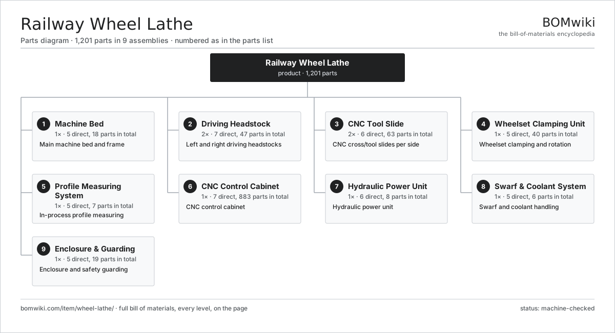
| # | Part | Qty | What it does |
|---|---|---|---|
| 1 | Machine Bed 5 parts | 1× | Main machine bed and frame |
| 2 | Driving Headstock 7 parts | 2× | Left and right driving headstocks |
| 3 | CNC Tool Slide 6 parts | 2× | CNC cross/tool slides per side |
| 4 | Wheelset Clamping Unit 5 parts | 1× | Wheelset clamping and rotation |
| 5 | Profile Measuring System 5 parts | 1× | In-process profile measuring |
| 6 | CNC Control Cabinet 7 parts | 1× | CNC control cabinet |
| 7 | Hydraulic Power Unit 6 parts | 1× | Hydraulic power unit |
| 8 | Swarf & Coolant System 5 parts | 1× | Swarf and coolant handling |
| 9 | Enclosure & Guarding 5 parts | 1× | Enclosure and safety guarding |
3D model
No 3D model yet. Have a CAD file of this? Add a 3D model — STL renders right on this page; STEP, FreeCAD, and OpenSCAD sources are welcome too (openly licensed, like all 3D models on BOMwiki).
Build & assembly graph
expand / collapse · shared sub-assemblies converge · links to related products · est. labourTap an assembly to expand/collapse · tap a part to open it · use “Open page” for any node · drag to pan, scroll to zoom.
Bill of materials for Railway Wheel Lathe
9 top-level lines · 89 rows shown · 1,201 parts total · indented to 3 levels| # | Item / sub-assembly | Part no. | Qty/assy | Ext. qty | Parts | Type |
|---|---|---|---|---|---|---|
| 1 | Machine Bed 5 parts | wheel-lathe-bed | 1× | 1 | 18 | assembly |
| 1.1 | Bed Casting | wheel-lathe-bed-casting | 1× | 1 | · | part |
| 1.2 | Linear Guide Rail | linear-guide | 4× | 4 | · | part |
| 1.3 | Leveling Foot | wheel-lathe-leveling-foot | 8× | 8 | · | part |
| 1.4 | Telescopic Way Cover | wheel-lathe-way-cover | 4× | 4 | · | part |
| 1.5 | Fastener Set | fastener-set | 1× | 1 | · | part |
| 2 | Driving Headstock 7 parts | wheel-lathe-headstock | 2× | 2 | 47 | assembly |
| 2.1 | Headstock Spindle | wheel-lathe-spindle | 1× | 2 | · | part |
| 2.2 | Gearbox Housing | gearbox-housing | 1× | 2 | · | part |
| 2.3 | Helical Gear Pair | gear-pair | 2× | 4 | · | part |
| 2.4 | Servo Motor 4 parts | servo-motor | 1× | 2 | 24 | assembly |
| 2.4.1 | Stator Assembly 3 parts + deeper › | stator-assembly | 1× | 2 | 3 | assembly |
| 2.4.2 | Rotor Assembly 4 parts + deeper › | rotor-assembly | 1× | 2 | 19 | assembly |
| 2.4.3 | Encoder | encoder | 1× | 2 | · | part |
| 2.4.4 | Motor Housing | motor-housing | 1× | 2 | · | part |
| 2.5 | Ball Bearing | ball-bearing | 4× | 8 | · | part |
| 2.6 | Oil Seal | oil-seal | 2× | 4 | · | part |
| 2.7 | Face Driver 3 parts | wheel-lathe-face-driver | 1× | 2 | 13 | assembly |
| 2.7.1 | Carbide Driver Pin | wheel-lathe-driver-pin | 6× | 12 | · | part |
| 2.7.2 | Coil Spring | coil-spring | 6× | 12 | · | part |
| 2.7.3 | Driver Body | wheel-lathe-driver-body | 1× | 2 | · | part |
| 3 | CNC Tool Slide 6 parts | wheel-lathe-tool-slide | 2× | 2 | 63 | assembly |
| 3.1 | Cross Slide (X) | wheel-lathe-cross-slide | 1× | 2 | · | part |
| 3.2 | Longitudinal Slide (Z) | wheel-lathe-z-slide | 1× | 2 | · | part |
| 3.3 | Ball Screw | ball-screw | 2× | 4 | · | part |
| 3.4 | Linear Guide Rail | linear-guide | 4× | 8 | · | part |
| 3.5 | Servo Motor 4 parts | servo-motor | 2× | 4 | 24 | assembly |
| 3.5.1 | Stator Assembly 3 parts + deeper › | stator-assembly | 1× | 4 | 3 | assembly |
| 3.5.2 | Rotor Assembly 4 parts + deeper › | rotor-assembly | 1× | 4 | 19 | assembly |
| 3.5.3 | Encoder | encoder | 1× | 4 | · | part |
| 3.5.4 | Motor Housing | motor-housing | 1× | 4 | · | part |
| 3.6 | Profiling Tool Block 3 parts | wheel-lathe-tool-block | 1× | 2 | 7 | assembly |
| 3.6.1 | Heavy Tool Holder | wheel-lathe-tool-holder | 2× | 4 | · | part |
| 3.6.2 | CBN Cutting Insert | wheel-lathe-insert | 4× | 8 | · | part |
| 3.6.3 | Fastener Set | fastener-set | 1× | 2 | · | part |
| 4 | Wheelset Clamping Unit 5 parts | wheel-lathe-clamping | 1× | 1 | 40 | assembly |
| 4.1 | Tailstock 3 parts | wheel-lathe-tailstock | 2× | 2 | 4 | assembly |
| 4.1.1 | Tailstock Quill | wheel-lathe-quill | 1× | 2 | · | part |
| 4.1.2 | Quill Cylinder | wheel-lathe-quill-cylinder | 1× | 2 | · | part |
| 4.1.3 | Ball Bearing | ball-bearing | 2× | 4 | · | part |
| 4.2 | Steady Rest 3 parts | wheel-lathe-steady-rest | 2× | 2 | 11 | assembly |
| 4.2.1 | Support Roller | wheel-lathe-support-roller | 3× | 6 | · | part |
| 4.2.2 | Ball Bearing | ball-bearing | 6× | 12 | · | part |
| 4.2.3 | Rest Arm | wheel-lathe-rest-arm | 2× | 4 | · | part |
| 4.3 | Live Center | wheel-lathe-center | 2× | 2 | · | part |
| 4.4 | Hydraulic Clamp Cylinder | wheel-lathe-clamp-cylinder | 4× | 4 | · | part |
| 4.5 | Ball Bearing | ball-bearing | 4× | 4 | · | part |
| 5 | Profile Measuring System 5 parts | wheel-lathe-measuring | 1× | 1 | 7 | assembly |
| 5.1 | Measuring Probe Arm | wheel-lathe-probe-arm | 2× | 2 | · | part |
| 5.2 | Touch Probe | wheel-lathe-touch-probe | 2× | 2 | · | part |
| 5.3 | Laser Profile Sensor | wheel-lathe-laser-sensor | 1× | 1 | · | part |
| 5.4 | Bare PCB | pcb-bare | 1× | 1 | · | part |
| 5.5 | Microcontroller | mcu | 1× | 1 | · | part |
| 6 | CNC Control Cabinet 7 parts | wheel-lathe-cnc | 1× | 1 | 883 | assembly |
| 6.1 | CNC Unit 3 parts | wheel-lathe-cnc-unit | 1× | 1 | 303 | assembly |
| 6.1.1 | Bare PCB | pcb-bare | 1× | 1 | · | part |
| 6.1.2 | Microcontroller | mcu | 2× | 2 | · | part |
| 6.1.3 | SMD Passive (R/C/L) | smd-passives | 300× | 300 | · | part |
| 6.2 | Servo Drive 3 parts | wheel-lathe-servo-drive | 6× | 6 | 87 | assembly |
| 6.2.1 | Bare PCB | pcb-bare | 1× | 6 | · | part |
| 6.2.2 | Power MOSFET | mosfet | 6× | 36 | · | part |
| 6.2.3 | SMD Passive (R/C/L) | smd-passives | 80× | 480 | · | part |
| 6.3 | Power Supply | power-supply | 2× | 2 | · | part |
| 6.4 | Operator HMI Panel 3 parts | wheel-lathe-hmi | 1× | 1 | 3 | assembly |
| 6.4.1 | LCD Panel | lcd-panel | 1× | 1 | · | part |
| 6.4.2 | Bare PCB | pcb-bare | 1× | 1 | · | part |
| 6.4.3 | Microcontroller | mcu | 1× | 1 | · | part |
| 6.5 | Relay | relay | 12× | 12 | · | part |
| 6.6 | Wire Bundle | wire-bundle | 1× | 1 | · | part |
| 6.7 | Connector | connector | 40× | 40 | · | part |
| 7 | Hydraulic Power Unit 6 parts | wheel-lathe-hydraulics | 1× | 1 | 8 | assembly |
| 7.1 | Variable Displacement Pump | wheel-lathe-hyd-pump | 1× | 1 | · | part |
| 7.2 | Hydraulic Tank | wheel-lathe-hyd-tank | 1× | 1 | · | part |
| 7.3 | Valve Manifold Block | wheel-lathe-valve-block | 1× | 1 | · | part |
| 7.4 | Pressure Sensor | pressure-sensor | 3× | 3 | · | part |
| 7.5 | O-Ring Set | oring-set | 1× | 1 | · | part |
| 7.6 | Hydraulic Accumulator | wheel-lathe-accumulator | 1× | 1 | · | part |
| 8 | Swarf & Coolant System 5 parts | wheel-lathe-chip-system | 1× | 1 | 6 | assembly |
| 8.1 | Hinged-Belt Chip Conveyor | wheel-lathe-chip-conveyor | 1× | 1 | · | part |
| 8.2 | Coolant Pump | wheel-lathe-coolant-pump | 1× | 1 | · | part |
| 8.3 | Coolant Tank | wheel-lathe-coolant-tank | 1× | 1 | · | part |
| 8.4 | Coolant Filter | wheel-lathe-coolant-filter | 1× | 1 | · | part |
| 8.5 | Drive Belt | drive-belt | 2× | 2 | · | part |
| 9 | Enclosure & Guarding 5 parts | wheel-lathe-guarding | 1× | 1 | 19 | assembly |
| 9.1 | Sheet Metal Panel | sheet-panel | 10× | 10 | · | part |
| 9.2 | Interlocked Access Door | wheel-lathe-access-door | 2× | 2 | · | part |
| 9.3 | Safety Interlock Switch | wheel-lathe-interlock | 4× | 4 | · | part |
| 9.4 | Work Light | wheel-lathe-light | 2× | 2 | · | part |
| 9.5 | Fastener Set | fastener-set | 1× | 1 | · | part |
Sourcing: possible vendors
Prices, MOQ, and lead times are algorithmic estimates, not quotes, and not claims about these companies. Company mappings are curated by keyword; est. price band $10k–$1M. How estimates work| Vendor | HQ | Specialty | MOQ | Lead time |
|---|---|---|---|---|
|
🇩🇪DMG MORI
dmgmori.com ↗
|
Bielefeld, DE | Machine tools | 5 units | 12–20 wks |
|
🇯🇵Mazak
mazak.com ↗
|
Oguchi, JP | Machine tools | 5 units | 12–20 wks |
| haascnc.com ↗ | Oxnard, US | CNC machine tools | 5 units | 12–20 wks |
|
🇯🇵Okuma
okuma.com ↗
|
Niwa, JP | Machine tools | 5 units | 12–20 wks |
|
🇩🇪Trumpf
trumpf.com ↗
|
Ditzingen, DE | Laser & sheet-metal machines | 5 units | 12–20 wks |
844-word article