Drag Finishing Machine
ProductOverview
A drag finishing machine improves the surface of high-value parts by pulling them through a bed of abrasive media at speed. The parts are not tumbled loose. Each part is clamped into its own holder and held at a fixed attitude while the machine drags it through the media in a controlled path. The result is a smooth, even, isotropic finish with no part-to-part contact, which matters when a single nick would scrap an expensive component. Typical work includes solid carbide cutting tools, forming and extrusion dies, orthopaedic implants, and aero engine blades and vanes. The process removes the sharp peaks left by grinding or machining, blends edges to a controlled radius, and can take a surface down to about 0.05 µm Ra without changing the part geometry in any way that matters.
The motion is planetary. The Carousel Turret Head is a large rotating turret that carries several work stations on a bolt circle. The whole turret rotates about the machine centre, and at the same time each Planetary Spindle Station spins about its own axis. So a part travels in a big circle around the tank while also rotating in place. That compound path sweeps the media past every face of the part from many directions, which is what produces an even finish rather than one flat polished side. The turret is lowered into the media by the Immersion Lift Axis, held at a programmed depth for the cycle, and then raised clear at the end.
How the drag process works
The media sits in a Annular Media Tank, a stationary ring-shaped bowl. The bed is a mix of abrasive chips and water with a small dose of compound. When the carousel lowers the parts into that bed and drags them through it, the chips flow against the part surface under the pressure of the bed itself. Material is removed where the chips press and slide hardest, on the peaks and the edges, and far less in the recesses. Because each part has its own holder, parts never touch each other and never touch the tank wall, so there is no impact damage and no flat spots from resting against another part. The finish is isotropic: there is no single lay direction, which is what cutting tools and gear flanks want for tool life and fatigue strength.
Finish is controlled by a few variables that the operator sets as a recipe: spindle speed, carousel speed, immersion depth, direction reversal, media grade, and cycle time. Running the spindle and carousel in opposite directions raises the relative velocity between part and media and cuts faster. Reversing direction part way through a cycle evens out any directional bias. Coarse ceramic media removes stock and rounds edges quickly; fine plastic or porcelain media polishes. Most recipes run a coarse stage followed by a fine stage.
Subsystems
The Carousel Turret Head is built on a heavy Turret Plate that rides on a Slewing Bearing and is turned through a Carousel Ring Gear. A Rotary Union feeds air and water from the static frame into the rotating head. Each station has a hardened Spindle Shaft running in a set of Ball Bearing units, sealed against slurry by an Oil Seal pair, with a Work Chuck and a part-specific Fixture Adapter at the working end.
Two drive trains move the work. The Carousel Drive uses a Servo Motor feeding the Carousel Reducer, a two-stage gearbox built from a Gearbox Housing and Helical Gear Pair sets, whose Drive Pinion meshes the ring gear. The Spindle Drive Train spins all the stations together through a common Spindle Drive Shaft and one Drive Belt per station, each kept tight by a Belt Tensioner. The vertical Immersion Lift Axis uses a Ball Screw running on Linear Guide Rail rails to set immersion depth, with a Immersion Proximity Sensor confirming the stroke limits.
The Fluid & Dosing System keeps the bed wet and conditioned: a Process Water Pump recirculates process water, a Compound Dosing Pump meters compound from the Compound Tank, and a Fluid Filter pulls fines out of the return. The Control Cabinet holds the PLC Module, a Servo Amplifier per axis, and a HMI Touchscreen for recipe selection. Everything sits on the Machine Frame & Guarding with interlocked guarding.
Materials
The wetted parts see abrasive slurry all day, so wear and corrosion drive the material choices. The Tank Shell is welded mild steel protected by a thick polyurethane Wear Liner. Spindle and drive shafts are 42CrMo4 hardened steel for fatigue strength. The ring gear and pinion are case-hardened 16MnCr5 for tooth wear life. Fixture adapters that touch the part are stainless steel so they do not rust against the workpiece. The turret plate is cast iron for stiffness and damping.
Variants and use
Machines are sized by the number of spindle stations, from four for a small tool shop up to twelve or sixteen for production. More stations means more parts per cycle but a larger tank and more drive power. Most machines are wet, running media in water with compound, which is the common case for cutting tools and implants. Dry drag machines run dry media such as walnut shell or corn cob with polishing paste for a final lustre and use no Fluid & Dosing System water loop. In a tool grinding plant a drag machine is the edge-prep step that hones the cutting edge to a defined radius and strips the grinding burr before coating. In medical work it polishes implant stems and bone screws. In aerospace it finishes compressor blades and vanes where surface quality drives both fatigue life and aerodynamic efficiency.
Drag Finishing Machine parts and their functions
9 top-level parts · 735 parts in total · full bill of materials below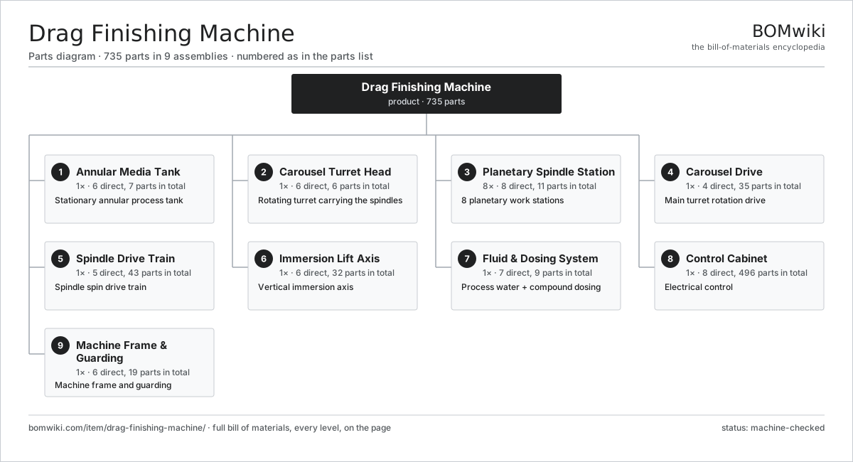
| # | Part | Qty | What it does |
|---|---|---|---|
| 1 | Annular Media Tank 6 parts | 1× | Stationary annular process tank |
| 2 | Carousel Turret Head 6 parts | 1× | Rotating turret carrying the spindles |
| 3 | Planetary Spindle Station 8 parts | 8× | 8 planetary work stations |
| 4 | Carousel Drive 4 parts | 1× | Main turret rotation drive |
| 5 | Spindle Drive Train 5 parts | 1× | Spindle spin drive train |
| 6 | Immersion Lift Axis 6 parts | 1× | Vertical immersion axis |
| 7 | Fluid & Dosing System 7 parts | 1× | Process water + compound dosing |
| 8 | Control Cabinet 8 parts | 1× | Electrical control |
| 9 | Machine Frame & Guarding 6 parts | 1× | Machine frame and guarding |
3D model
No 3D model yet. Have a CAD file of this? Add a 3D model — STL renders right on this page; STEP, FreeCAD, and OpenSCAD sources are welcome too (openly licensed, like all 3D models on BOMwiki).
Build & assembly graph
expand / collapse · shared sub-assemblies converge · links to related products · est. labourTap an assembly to expand/collapse · tap a part to open it · use “Open page” for any node · drag to pan, scroll to zoom.
Bill of materials for Drag Finishing Machine
9 top-level lines · 91 rows shown · 735 parts total · indented to 3 levels| # | Item / sub-assembly | Part no. | Qty/assy | Ext. qty | Parts | Type |
|---|---|---|---|---|---|---|
| 1 | Annular Media Tank 6 parts | drag-finishing-machine-media-tank | 1× | 1 | 7 | assembly |
| 1.1 | Tank Shell | drag-finishing-machine-tank-shell | 1× | 1 | · | part |
| 1.2 | Wear Liner | drag-finishing-machine-tank-liner | 1× | 1 | · | part |
| 1.3 | Abrasive Media Charge | drag-finishing-machine-media-charge | 1× | 1 | · | part |
| 1.4 | Tank Drain Valve | drag-finishing-machine-tank-drain-valve | 2× | 2 | · | part |
| 1.5 | Overflow Weir | drag-finishing-machine-tank-overflow-weir | 1× | 1 | · | part |
| 1.6 | Fastener Set | fastener-set | 1× | 1 | · | part |
| 2 | Carousel Turret Head 6 parts | drag-finishing-machine-carousel-head | 1× | 1 | 6 | assembly |
| 2.1 | Turret Plate | drag-finishing-machine-turret-plate | 1× | 1 | · | part |
| 2.2 | Slewing Bearing | drag-finishing-machine-slewing-bearing | 1× | 1 | · | part |
| 2.3 | Carousel Hub Shaft | drag-finishing-machine-hub-shaft | 1× | 1 | · | part |
| 2.4 | Carousel Ring Gear | drag-finishing-machine-ring-gear | 1× | 1 | · | part |
| 2.5 | Rotary Union | drag-finishing-machine-rotary-union | 1× | 1 | · | part |
| 2.6 | Fastener Set | fastener-set | 1× | 1 | · | part |
| 3 | Planetary Spindle Station 8 parts | drag-finishing-machine-spindle-station | 8× | 8 | 11 | assembly |
| 3.1 | Spindle Shaft | drag-finishing-machine-spindle-shaft | 1× | 8 | · | part |
| 3.2 | Work Chuck | drag-finishing-machine-work-chuck | 1× | 8 | · | part |
| 3.3 | Fixture Adapter | drag-finishing-machine-fixture-adapter | 1× | 8 | · | part |
| 3.4 | Spindle Pulley | drag-finishing-machine-spindle-pulley | 1× | 8 | · | part |
| 3.5 | Ball Bearing | ball-bearing | 3× | 24 | · | part |
| 3.6 | Oil Seal | oil-seal | 2× | 16 | · | part |
| 3.7 | Spindle Housing | drag-finishing-machine-spindle-housing | 1× | 8 | · | part |
| 3.8 | Fastener Set | fastener-set | 1× | 8 | · | part |
| 4 | Carousel Drive 4 parts | drag-finishing-machine-carousel-drive | 1× | 1 | 35 | assembly |
| 4.1 | Servo Motor 4 parts | servo-motor | 1× | 1 | 24 | assembly |
| 4.1.1 | Stator Assembly 3 parts + deeper › | stator-assembly | 1× | 1 | 3 | assembly |
| 4.1.2 | Rotor Assembly 4 parts + deeper › | rotor-assembly | 1× | 1 | 19 | assembly |
| 4.1.3 | Encoder | encoder | 1× | 1 | · | part |
| 4.1.4 | Motor Housing | motor-housing | 1× | 1 | · | part |
| 4.2 | Carousel Reducer 4 parts | drag-finishing-machine-carousel-reducer | 1× | 1 | 9 | assembly |
| 4.2.1 | Gearbox Housing | gearbox-housing | 1× | 1 | · | part |
| 4.2.2 | Helical Gear Pair | gear-pair | 2× | 2 | · | part |
| 4.2.3 | Ball Bearing | ball-bearing | 4× | 4 | · | part |
| 4.2.4 | Oil Seal | oil-seal | 2× | 2 | · | part |
| 4.3 | Drive Pinion | drag-finishing-machine-drive-pinion | 1× | 1 | · | part |
| 4.4 | Fastener Set | fastener-set | 1× | 1 | · | part |
| 5 | Spindle Drive Train 5 parts | drag-finishing-machine-spindle-drive | 1× | 1 | 43 | assembly |
| 5.1 | Servo Motor 4 parts | servo-motor | 1× | 1 | 24 | assembly |
| 5.1.1 | Stator Assembly 3 parts + deeper › | stator-assembly | 1× | 1 | 3 | assembly |
| 5.1.2 | Rotor Assembly 4 parts + deeper › | rotor-assembly | 1× | 1 | 19 | assembly |
| 5.1.3 | Encoder | encoder | 1× | 1 | · | part |
| 5.1.4 | Motor Housing | motor-housing | 1× | 1 | · | part |
| 5.2 | Spindle Drive Shaft | drag-finishing-machine-drive-shaft | 1× | 1 | · | part |
| 5.3 | Drive Belt | drive-belt | 8× | 8 | · | part |
| 5.4 | Belt Tensioner | drag-finishing-machine-belt-tensioner | 8× | 8 | · | part |
| 5.5 | Ball Bearing | ball-bearing | 2× | 2 | · | part |
| 6 | Immersion Lift Axis 6 parts | drag-finishing-machine-lift-axis | 1× | 1 | 32 | assembly |
| 6.1 | Ball Screw | ball-screw | 1× | 1 | · | part |
| 6.2 | Linear Guide Rail | linear-guide | 2× | 2 | · | part |
| 6.3 | Servo Motor 4 parts | servo-motor | 1× | 1 | 24 | assembly |
| 6.3.1 | Stator Assembly 3 parts + deeper › | stator-assembly | 1× | 1 | 3 | assembly |
| 6.3.2 | Rotor Assembly 4 parts + deeper › | rotor-assembly | 1× | 1 | 19 | assembly |
| 6.3.3 | Encoder | encoder | 1× | 1 | · | part |
| 6.3.4 | Motor Housing | motor-housing | 1× | 1 | · | part |
| 6.4 | Lift Carriage | drag-finishing-machine-lift-carriage | 1× | 1 | · | part |
| 6.5 | Immersion Proximity Sensor | drag-finishing-machine-immersion-prox-sensor | 2× | 2 | · | part |
| 6.6 | Ball Bearing | ball-bearing | 2× | 2 | · | part |
| 7 | Fluid & Dosing System 7 parts | drag-finishing-machine-fluid-system | 1× | 1 | 9 | assembly |
| 7.1 | Process Water Pump | drag-finishing-machine-water-pump | 1× | 1 | · | part |
| 7.2 | Compound Dosing Pump | drag-finishing-machine-dosing-pump | 1× | 1 | · | part |
| 7.3 | Compound Tank | drag-finishing-machine-compound-tank | 1× | 1 | · | part |
| 7.4 | Fluid Filter | drag-finishing-machine-fluid-filter | 1× | 1 | · | part |
| 7.5 | Pressure Sensor | pressure-sensor | 1× | 1 | · | part |
| 7.6 | Solenoid Valve | drag-finishing-machine-solenoid-valve | 3× | 3 | · | part |
| 7.7 | O-Ring Set | oring-set | 1× | 1 | · | part |
| 8 | Control Cabinet 8 parts | drag-finishing-machine-control-cabinet | 1× | 1 | 496 | assembly |
| 8.1 | PLC Module 3 parts | drag-finishing-machine-plc | 1× | 1 | 122 | assembly |
| 8.1.1 | Bare PCB | pcb-bare | 1× | 1 | · | part |
| 8.1.2 | Microcontroller | mcu | 1× | 1 | · | part |
| 8.1.3 | SMD Passive (R/C/L) | smd-passives | 120× | 120 | · | part |
| 8.2 | Servo Amplifier 3 parts | drag-finishing-machine-servo-amplifier | 3× | 3 | 92 | assembly |
| 8.2.1 | Bare PCB | pcb-bare | 1× | 3 | · | part |
| 8.2.2 | Microcontroller | mcu | 1× | 3 | · | part |
| 8.2.3 | SMD Passive (R/C/L) | smd-passives | 90× | 270 | · | part |
| 8.3 | HMI Touchscreen 4 parts | drag-finishing-machine-hmi-screen | 1× | 1 | 63 | assembly |
| 8.3.1 | LCD Panel | lcd-panel | 1× | 1 | · | part |
| 8.3.2 | Bare PCB | pcb-bare | 1× | 1 | · | part |
| 8.3.3 | Microcontroller | mcu | 1× | 1 | · | part |
| 8.3.4 | SMD Passive (R/C/L) | smd-passives | 60× | 60 | · | part |
| 8.4 | Power Supply | power-supply | 1× | 1 | · | part |
| 8.5 | Relay | relay | 8× | 8 | · | part |
| 8.6 | Terminal Block Set | drag-finishing-machine-terminal-block | 1× | 1 | · | part |
| 8.7 | Wire Bundle | wire-bundle | 1× | 1 | · | part |
| 8.8 | Connector | connector | 24× | 24 | · | part |
| 9 | Machine Frame & Guarding 6 parts | drag-finishing-machine-frame | 1× | 1 | 19 | assembly |
| 9.1 | Base Frame | drag-finishing-machine-base-frame | 1× | 1 | · | part |
| 9.2 | Lift Column | drag-finishing-machine-column | 2× | 2 | · | part |
| 9.3 | Sheet Metal Panel | sheet-panel | 8× | 8 | · | part |
| 9.4 | Interlocked Guard Door | drag-finishing-machine-guard-door | 1× | 1 | · | part |
| 9.5 | Leveling Foot | drag-finishing-machine-leveling-foot | 6× | 6 | · | part |
| 9.6 | Fastener Set | fastener-set | 1× | 1 | · | part |
Related products
same domain, ranked by shared parts Creep-Feed Grinder
571 parts · shares 9 with this page
Creep-Feed Grinder
571 parts · shares 9 with this page
 Railway Wheel Lathe
1,201 parts · shares 9 with this page
Railway Wheel Lathe
1,201 parts · shares 9 with this page
 Rotary-Table Surface Grinder
172 parts · shares 9 with this page
Rotary-Table Surface Grinder
172 parts · shares 9 with this page
 Shot Peening Machine
586 parts · shares 9 with this page
Spring End Grinding Machine
1,048 parts · shares 9 with this page
Strip Edge Trimming Machine
491 parts · shares 9 with this page
Shot Peening Machine
586 parts · shares 9 with this page
Spring End Grinding Machine
1,048 parts · shares 9 with this page
Strip Edge Trimming Machine
491 parts · shares 9 with this page
Sourcing: possible vendors
Prices, MOQ, and lead times are algorithmic estimates, not quotes, and not claims about these companies. Company mappings are curated by keyword; est. price band $10k–$1M. How estimates work| Vendor | HQ | Specialty | MOQ | Lead time |
|---|---|---|---|---|
|
🇩🇪DMG MORI
dmgmori.com ↗
|
Bielefeld, DE | Machine tools | 5 units | 12–20 wks |
|
🇯🇵Mazak
mazak.com ↗
|
Oguchi, JP | Machine tools | 5 units | 12–20 wks |
| haascnc.com ↗ | Oxnard, US | CNC machine tools | 5 units | 12–20 wks |
|
🇯🇵Okuma
okuma.com ↗
|
Niwa, JP | Machine tools | 5 units | 12–20 wks |
|
🇩🇪Trumpf
trumpf.com ↗
|
Ditzingen, DE | Laser & sheet-metal machines | 5 units | 12–20 wks |
1,026-word article