Hydraulic Shaper
ProductOverview
A hydraulic shaper cuts flat surfaces with a single-point tool that reciprocates horizontally, the same basic action as a mechanical shaper, but the ram is driven by oil pressure instead of a crank and rocker arm. That single change improves the machine in several ways. Hydraulic drive gives a near-constant cutting speed across the whole stroke instead of the varying speed a crank produces, it provides a quick return automatically, and it sets a controllable cutting force through a pressure relief rather than a fixed mechanical advantage. The tool is carried on the Ram Assembly, pushed forward by the Hydraulic Drive, and cuts on the forward stroke while the Feed System indexes the Worktable sideways between strokes. Shapers are simple, cheap to tool, and forgiving, which keeps them in toolrooms and repair shops for machining flats, slots, dovetails and angular surfaces on one-off parts.
Base, column and ram ways
The structure is a grey iron Base and Column assembly. The Base Casting carries the worktable and houses the coolant tank, and the Column is a box casting that holds the hydraulic cylinder and the horizontal Ram Ways. Those ways are hand-scraped dovetails, kept tight by Way Gibs strips, so the ram slides straight and true along the cutting line. Grey iron is used throughout for its vibration damping. Because a shaper cuts intermittently, once per stroke, any springiness in the structure shows up as chatter marks on the work, so stiffness and damping in the base and column directly set the surface finish.
Ram and tool head
The Ram is a hardened steel slide that reciprocates on the ways. It is joined to the piston rod by a Ram-Cylinder Coupling, and adjustable Stroke Stops on the ram trip the reversing valve at each end. Moving these stops sets both the length of the stroke and where it sits relative to the work, which is how the operator matches the stroke to the part. At the front of the ram is the Tool Head. Its heart is the Clapper Box, a pivoting box that lets the Tool Bit lift slightly on the idle return stroke so it does not drag back across the cut surface, then drops back for the next forward cut. The Tool Slide feeds the tool down to set depth of cut and machine vertical faces, the Tool Post clamps the tool, and a graduated Swivel Base lets the whole head swivel for angular cuts such as dovetails.
Worktable and workholding
The Worktable holds the part. The slotted Table Casting rides on a vertical Cross Rail that raises and lowers it to suit the work height, and a Table Support braces the front of the table against the cutting force so it does not deflect. Most work is held in a swivel Machine Vise bolted to the table, though large or awkward parts are clamped directly to the slots. The table moves across the line of cut to feed the work past the tool, and that cross motion is what turns a series of single-line cuts into a finished flat surface.
Hydraulic drive and quick return
The Hydraulic Drive is what distinguishes this machine. A Hydraulic Pump driven by a Pump Motor of 2–7.5 kW supplies oil from the Oil Tank to a double-acting Main Cylinder that pushes the ram. At each end of the stroke, the ram stops trip a Reversing Valve that switches oil to the other side of the piston, reversing direction. Because the two sides of the piston have different effective areas, the return stroke runs faster than the cutting stroke, giving an automatic quick return that shortens cycle time. A Relief Valve sets the maximum cutting pressure: if the tool meets a hard spot or too heavy a cut, the relief opens and the ram simply slows or stalls instead of breaking the tool, a built-in overload protection a mechanical shaper does not have. Sealing uses standard Oil Seal and O-Ring Set components.
Feed system
Between strokes the work has to advance sideways by a controlled amount, and on a hydraulic shaper this is done hydraulically too. A small Feed Cylinder pulses once per stroke, turning the cross Feed Screw by a fixed increment. The amount is set by a Feed Rate Valve that throttles the oil to the feed cylinder, giving any feed from about 0.05 to 2 mm per stroke. Finer feeds give a better finish on the final passes; coarser feeds clear stock quickly on roughing. The feed is timed to occur during the return stroke so the table is stationary while the tool is cutting.
Electrical, coolant, materials and use
The Electrical System system is simple: a Motor Contactor switches the pump motor, a Pressure Sensor confirms hydraulic pressure before motion is allowed, and a few Relay units with a Power Supply handle the control logic, wired through a Wire Bundle and Connector set. The Coolant System uses a Coolant Pump drawing from the Coolant Tank to feed a Coolant Nozzle at the tool. Castings are grey iron; the ram, ways and tool head are alloy steels hardened at the wear surfaces. Hydraulic shapers handle strokes from 100 to 600 mm and reach surface finishes around Ra 3–8 micron. They are used for machining flats, keyseats, dovetail slides, splines and angular surfaces on individual parts and repairs, where setting up a milling cutter would be slower or where the part shape suits a single-point tool. The constant cutting speed, automatic quick return and pressure-limited cutting force make the hydraulic version smoother and safer to run than the older crank-driven design.
Hydraulic Shaper parts and their functions
8 top-level parts · 49 parts in total · full bill of materials below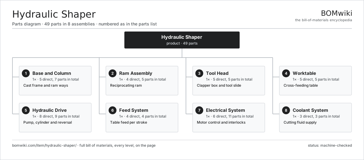
| # | Part | Qty | What it does |
|---|---|---|---|
| 1 | Base and Column 5 parts | 1× | Cast frame and ram ways |
| 2 | Ram Assembly 4 parts | 1× | Reciprocating ram |
| 3 | Tool Head 5 parts | 1× | Clapper box and tool slide |
| 4 | Worktable 5 parts | 1× | Cross-feeding table |
| 5 | Hydraulic Drive 8 parts | 1× | Pump, cylinder and reversal |
| 6 | Feed System 4 parts | 1× | Table feed per stroke |
| 7 | Electrical System 6 parts | 1× | Motor control and interlocks |
| 8 | Coolant System 3 parts | 1× | Cutting fluid supply |
3D model
No 3D model yet. Have a CAD file of this? Add a 3D model — STL renders right on this page; STEP, FreeCAD, and OpenSCAD sources are welcome too (openly licensed, like all 3D models on BOMwiki).
Build & assembly graph
expand / collapse · shared sub-assemblies converge · links to related products · est. labourTap an assembly to expand/collapse · tap a part to open it · use “Open page” for any node · drag to pan, scroll to zoom.
Bill of materials for Hydraulic Shaper
8 top-level lines · 48 rows shown · 49 parts total · indented to 3 levels| # | Item / sub-assembly | Part no. | Qty/assy | Ext. qty | Parts | Type |
|---|---|---|---|---|---|---|
| 1 | Base and Column 5 parts | hydraulic-shaper-base-column | 1× | 1 | 7 | assembly |
| 1.1 | Base Casting | hydraulic-shaper-base-casting | 1× | 1 | · | part |
| 1.2 | Column | hydraulic-shaper-column | 1× | 1 | · | part |
| 1.3 | Ram Ways | hydraulic-shaper-ram-ways | 1× | 1 | · | part |
| 1.4 | Way Gibs | hydraulic-shaper-ways-gib | 2× | 2 | · | part |
| 1.5 | Fastener Set | fastener-set | 2× | 2 | · | part |
| 2 | Ram Assembly 4 parts | hydraulic-shaper-ram-assembly | 1× | 1 | 5 | assembly |
| 2.1 | Ram | hydraulic-shaper-ram | 1× | 1 | · | part |
| 2.2 | Ram-Cylinder Coupling | hydraulic-shaper-ram-cylinder-coupling | 1× | 1 | · | part |
| 2.3 | Stroke Stops | hydraulic-shaper-stroke-stops | 2× | 2 | · | part |
| 2.4 | Fastener Set | fastener-set | 1× | 1 | · | part |
| 3 | Tool Head 5 parts | hydraulic-shaper-tool-head | 1× | 1 | 5 | assembly |
| 3.1 | Clapper Box | hydraulic-shaper-clapper-box | 1× | 1 | · | part |
| 3.2 | Tool Slide | hydraulic-shaper-tool-slide | 1× | 1 | · | part |
| 3.3 | Tool Post | hydraulic-shaper-tool-post | 1× | 1 | · | part |
| 3.4 | Tool Bit | hydraulic-shaper-tool-bit | 1× | 1 | · | part |
| 3.5 | Swivel Base | hydraulic-shaper-swivel-base | 1× | 1 | · | part |
| 4 | Worktable 5 parts | hydraulic-shaper-worktable | 1× | 1 | 5 | assembly |
| 4.1 | Table Casting | hydraulic-shaper-table-casting | 1× | 1 | · | part |
| 4.2 | Cross Rail | hydraulic-shaper-cross-rail | 1× | 1 | · | part |
| 4.3 | Machine Vise | hydraulic-shaper-vise | 1× | 1 | · | part |
| 4.4 | Table Support | hydraulic-shaper-table-support | 1× | 1 | · | part |
| 4.5 | Fastener Set | fastener-set | 1× | 1 | · | part |
| 5 | Hydraulic Drive 8 parts | hydraulic-shaper-hydraulic-drive | 1× | 1 | 9 | assembly |
| 5.1 | Hydraulic Pump | hydraulic-shaper-pump | 1× | 1 | · | part |
| 5.2 | Pump Motor | hydraulic-shaper-drive-motor | 1× | 1 | · | part |
| 5.3 | Main Cylinder | hydraulic-shaper-main-cylinder | 1× | 1 | · | part |
| 5.4 | Reversing Valve | hydraulic-shaper-reversing-valve | 1× | 1 | · | part |
| 5.5 | Relief Valve | hydraulic-shaper-relief-valve | 1× | 1 | · | part |
| 5.6 | Oil Tank | hydraulic-shaper-oil-tank | 1× | 1 | · | part |
| 5.7 | Oil Seal | oil-seal | 2× | 2 | · | part |
| 5.8 | O-Ring Set | oring-set | 1× | 1 | · | part |
| 6 | Feed System 4 parts | hydraulic-shaper-feed-system | 1× | 1 | 4 | assembly |
| 6.1 | Feed Cylinder | hydraulic-shaper-feed-cylinder | 1× | 1 | · | part |
| 6.2 | Feed Screw | hydraulic-shaper-feed-screw | 1× | 1 | · | part |
| 6.3 | Feed Rate Valve | hydraulic-shaper-feed-rate-valve | 1× | 1 | · | part |
| 6.4 | Fastener Set | fastener-set | 1× | 1 | · | part |
| 7 | Electrical System 6 parts | hydraulic-shaper-electrical | 1× | 1 | 11 | assembly |
| 7.1 | Motor Contactor | hydraulic-shaper-contactor | 1× | 1 | · | part |
| 7.2 | Relay | relay | 2× | 2 | · | part |
| 7.3 | Pressure Sensor | pressure-sensor | 1× | 1 | · | part |
| 7.4 | Power Supply | power-supply | 1× | 1 | · | part |
| 7.5 | Wire Bundle | wire-bundle | 1× | 1 | · | part |
| 7.6 | Connector | connector | 5× | 5 | · | part |
| 8 | Coolant System 3 parts | hydraulic-shaper-coolant-system | 1× | 1 | 3 | assembly |
| 8.1 | Coolant Pump | hydraulic-shaper-coolant-pump | 1× | 1 | · | part |
| 8.2 | Coolant Tank | hydraulic-shaper-coolant-tank | 1× | 1 | · | part |
| 8.3 | Coolant Nozzle | hydraulic-shaper-coolant-nozzle | 1× | 1 | · | part |
Related products
same domain, ranked by shared parts Abrasive Flow Machining Machine
279 parts · shares 1 with this page
Abrasive Flow Machining Machine
279 parts · shares 1 with this page
 Aluminum Extrusion Press
365 parts · shares 1 with this page
Aluminum Extrusion Press
365 parts · shares 1 with this page
 Angle Roll Bender
100 parts · shares 1 with this page
Bar Chamfering Machine
1,148 parts · shares 1 with this page
Angle Roll Bender
100 parts · shares 1 with this page
Bar Chamfering Machine
1,148 parts · shares 1 with this page
 Bed-Type Milling Machine
151 parts · shares 1 with this page
Bed-Type Milling Machine
151 parts · shares 1 with this page
 Bevel Gear Generator
201 parts · shares 1 with this page
Bevel Gear Generator
201 parts · shares 1 with this page
Sourcing: possible vendors
Prices, MOQ, and lead times are algorithmic estimates, not quotes, and not claims about these companies. Company mappings are curated by keyword; est. price band $10k–$1M. How estimates work| Vendor | HQ | Specialty | MOQ | Lead time |
|---|---|---|---|---|
|
🇩🇪DMG MORI
dmgmori.com ↗
|
Bielefeld, DE | Machine tools | 5 units | 12–20 wks |
|
🇯🇵Mazak
mazak.com ↗
|
Oguchi, JP | Machine tools | 5 units | 12–20 wks |
| haascnc.com ↗ | Oxnard, US | CNC machine tools | 5 units | 12–20 wks |
|
🇯🇵Okuma
okuma.com ↗
|
Niwa, JP | Machine tools | 5 units | 12–20 wks |
|
🇩🇪Trumpf
trumpf.com ↗
|
Ditzingen, DE | Laser & sheet-metal machines | 5 units | 12–20 wks |
1,020-word article