Mechanical Power Press
ProductOverview
A mechanical power press stamps parts from sheet metal by converting stored rotational energy into a short, powerful linear stroke. A motor keeps a heavy Flywheel spinning continuously; when the operator signals a stroke, a clutch couples the flywheel to a crankshaft for one rotation, the Slide descends, the die does its work, and a brake stops the slide at the top. Because the energy comes from the flywheel rather than from a pump driven in real time, the press can deliver hundreds of strokes per minute, which makes it the workhorse for high-volume stamping: brackets, washers, panels, can lids, and progressive-die parts.
The defining difference from a Hydraulic Punch Press is that the stroke is fixed and tied to the crank angle. The press makes its full tonnage only near the bottom of the stroke and cannot pause or vary force partway down. That gives speed but demands careful tooling and serious operator protection, because the slide cannot be stopped instantly once it is committed. The machine is built from a Press Frame, a Flywheel Drive, a Clutch and Brake, a Crank Mechanism, the slide, Bolster and Tooling, a Counterbalance System, a Lubrication System, a Control System, and a Safety System.
Frame
Two frame styles are common. A gap (C) frame is open at the front for easy feeding but tends to spring open under load. A straight-side (O) frame, used here, ties two Frame Upright between the Crown and the Bed with pre-tensioned Tie Rod members, which keeps deflection low and tolerates off-centre loads from progressive dies. The slide runs in adjustable Slide Gib guides set with small clearance, because a loose slide will tip under an off-centre hit and ruin part quality.
Flywheel Drive
The Flywheel Drive is what gives the press its character. A Drive Motor of 15 to 110 kW runs continuously through a Drive Belt set, keeping the cast-iron Flywheel at speed. The flywheel stores the stamping energy; during the brief instant the die cuts, the slide draws heavily on that stored energy and the flywheel slows slightly, then the motor brings it back up to speed before the next stroke. Sizing the flywheel and motor to the energy per stroke and the stroke rate is a basic part of press design.
Clutch, Brake and Crank
The Clutch and Brake is the heart of the control. A pneumatic Clutch Pack couples the flywheel to the crankshaft when the press is signalled to cycle, while a spring-set, air-released Brake Pack stops the slide at top dead centre and fails safe if air is lost. A Dual Safety Valve, a redundant monitored dual safety valve, controls the air and detects a stuck spool, which is mandatory on a power press. A Rotary Cam Switch reports crank angle for feed timing and the safety window. The Crank Mechanism then converts rotation to stroke: a forged Crankshaft whose throw sets the stroke length drives a Connecting Rod that pushes the slide, with a Shut-Height Adjust Screw screw setting the closed height for each die.
Slide and Tooling
The Slide Body carries the upper die on a ground Slide Face. Inside it sits a Hydraulic Overload Protector, a hydraulic cell that collapses if the tonnage exceeds the rating, which saves the press from a mis-set die or a double-thickness slug. The work is done by the Bolster and Tooling: a Stamping Die Set of punch, die block and stripper mounted on the Bolster Plate, fed by a Coil Feed that advances strip from a coil by the part pitch each stroke, in time with the crank angle.
Counterbalance and Lubrication
The Counterbalance System uses air Counterbalance Cylinder units to carry the dead weight of the slide and upper die. This keeps the connecting-rod bearings loaded in one direction (removing backlash and pounding), and it eases the duty on the brake so it can hold the slide at the top. The Lubrication System is automatic: a timed Lube Pump feeds metered oil through a Lube Manifold to the crank bearings, gibs and screws, since a press running hundreds of strokes a minute would quickly destroy a dry bearing.
Control and Safety
The Control System runs on a safety-rated Press Controller that sequences the clutch-brake against crank angle and runs the feed. A Brake Stop-Time Monitor measures the slide stopping time on every stroke, which matters because the operator guarding depends on it. Since the slide cannot stop instantly, the Safety System sets its Safety Light Curtain back from the die by a safe distance calculated from the measured stop time, so a hand reaching in triggers a stop before it can reach the closing tools. An anti-tie-down Two-Hand Control starts each stroke and every E-Stop runs through a monitored Safety Relay.
Variants and Use
Mechanical presses span 25 ton open-frame units for small blanking up to 1,000 ton straight-side presses for large body panels, with stroke rates from about 60 per minute on big machines to 800 per minute on small high-speed presses. Crank presses give a sinusoidal stroke; knuckle-joint and link-drive variants slow the slide near the bottom for coining and deep forming. For long runs of a fixed part, the mechanical press is the most productive and energy-efficient choice. Where the job needs full force throughout the stroke, a controllable dwell, or built-in overload tolerance, a Hydraulic Punch Press or a Servo Stamping Press is preferred instead.
Mechanical Power Press parts and their functions
10 top-level parts · 400 parts in total · full bill of materials below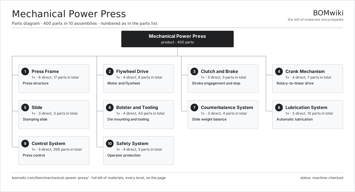
| # | Part | Qty | What it does |
|---|---|---|---|
| 1 | Press Frame 6 parts | 1× | Press structure |
| 2 | Flywheel Drive 4 parts | 1× | Motor and flywheel |
| 3 | Clutch and Brake 5 parts | 1× | Stroke engagement and stop |
| 4 | Crank Mechanism 4 parts | 1× | Rotary-to-linear drive |
| 5 | Slide 3 parts | 1× | Stamping slide |
| 6 | Bolster and Tooling 4 parts | 1× | Die mounting and tooling |
| 7 | Counterbalance System 3 parts | 1× | Slide weight balance |
| 8 | Lubrication System 3 parts | 1× | Automatic lubrication |
| 9 | Control System 5 parts | 1× | Press control |
| 10 | Safety System 4 parts | 1× | Operator protection |
3D model
No 3D model yet. Have a CAD file of this? Add a 3D model — STL renders right on this page; STEP, FreeCAD, and OpenSCAD sources are welcome too (openly licensed, like all 3D models on BOMwiki).
Build & assembly graph
expand / collapse · shared sub-assemblies converge · links to related products · est. labourTap an assembly to expand/collapse · tap a part to open it · use “Open page” for any node · drag to pan, scroll to zoom.
Bill of materials for Mechanical Power Press
10 top-level lines · 72 rows shown · 400 parts total · indented to 3 levels| # | Item / sub-assembly | Part no. | Qty/assy | Ext. qty | Parts | Type |
|---|---|---|---|---|---|---|
| 1 | Press Frame 6 parts | mpp-frame | 1× | 1 | 17 | assembly |
| 1.1 | Frame Upright | mpp-frame-uprights | 2× | 2 | · | part |
| 1.2 | Crown | mpp-crown | 1× | 1 | · | part |
| 1.3 | Bed | mpp-bed | 1× | 1 | · | part |
| 1.4 | Tie Rod | mpp-tie-rod | 4× | 4 | · | part |
| 1.5 | Slide Gib | mpp-slide-gib | 8× | 8 | · | part |
| 1.6 | Fastener Set | fastener-set | 1× | 1 | · | part |
| 2 | Flywheel Drive 4 parts | mpp-flywheel-drive | 1× | 1 | 8 | assembly |
| 2.1 | Drive Motor | mpp-drive-motor | 1× | 1 | · | part |
| 2.2 | Flywheel | mpp-flywheel | 1× | 1 | · | part |
| 2.3 | Drive Belt | drive-belt | 4× | 4 | · | part |
| 2.4 | Ball Bearing | ball-bearing | 2× | 2 | · | part |
| 3 | Clutch and Brake 5 parts | mpp-clutch-brake | 1× | 1 | 5 | assembly |
| 3.1 | Clutch Pack | mpp-clutch-pack | 1× | 1 | · | part |
| 3.2 | Brake Pack | mpp-brake-pack | 1× | 1 | · | part |
| 3.3 | Clutch Air Cylinder | mpp-air-cylinder | 1× | 1 | · | part |
| 3.4 | Rotary Cam Switch | mpp-rotary-cam | 1× | 1 | · | part |
| 3.5 | Dual Safety Valve | mpp-clutch-valve | 1× | 1 | · | part |
| 4 | Crank Mechanism 4 parts | mpp-crank-mechanism | 1× | 1 | 7 | assembly |
| 4.1 | Crankshaft | mpp-crankshaft | 1× | 1 | · | part |
| 4.2 | Connecting Rod | mpp-connecting-rod | 1× | 1 | · | part |
| 4.3 | Shut-Height Adjust Screw | mpp-shut-height-adjust | 1× | 1 | · | part |
| 4.4 | Crank Bearing | mpp-crank-bearing | 4× | 4 | · | part |
| 5 | Slide 3 parts | mpp-slide | 1× | 1 | 3 | assembly |
| 5.1 | Slide Body | mpp-slide-body | 1× | 1 | · | part |
| 5.2 | Slide Face | mpp-slide-face | 1× | 1 | · | part |
| 5.3 | Hydraulic Overload Protector | mpp-overload-protector | 1× | 1 | · | part |
| 6 | Bolster and Tooling 4 parts | mpp-bolster-tooling | 1× | 1 | 43 | assembly |
| 6.1 | Bolster Plate | mpp-bolster-plate | 1× | 1 | · | part |
| 6.2 | Stamping Die Set 5 parts | mpp-die-set | 1× | 1 | 11 | assembly |
| 6.2.1 | Die Punch | mpp-die-punch | 1× | 1 | · | part |
| 6.2.2 | Die Block | mpp-die-block | 1× | 1 | · | part |
| 6.2.3 | Die Stripper | mpp-die-stripper | 1× | 1 | · | part |
| 6.2.4 | Coil Spring | coil-spring | 4× | 4 | · | part |
| 6.2.5 | Ball Bearing | ball-bearing | 4× | 4 | · | part |
| 6.3 | Coil Feed 3 parts | mpp-coil-feed | 1× | 1 | 27 | assembly |
| 6.3.1 | Feed Roll | mpp-feed-roll | 2× | 2 | · | part |
| 6.3.2 | Servo Motor 4 parts + deeper › | servo-motor | 1× | 1 | 24 | assembly |
| 6.3.3 | Coil Straightener | mpp-straightener | 1× | 1 | · | part |
| 6.4 | Die Clamp | mpp-die-clamp | 4× | 4 | · | part |
| 7 | Counterbalance System 3 parts | mpp-counterbalance | 1× | 1 | 4 | assembly |
| 7.1 | Counterbalance Cylinder | mpp-balance-cylinder | 2× | 2 | · | part |
| 7.2 | Air Regulator | mpp-air-regulator | 1× | 1 | · | part |
| 7.3 | Air Receiver | mpp-air-tank | 1× | 1 | · | part |
| 8 | Lubrication System 3 parts | mpp-lubrication-system | 1× | 1 | 10 | assembly |
| 8.1 | Lube Pump | mpp-lube-pump | 1× | 1 | · | part |
| 8.2 | Lube Manifold | mpp-lube-manifold | 1× | 1 | · | part |
| 8.3 | Lube Line | mpp-lube-line | 8× | 8 | · | part |
| 9 | Control System 5 parts | mpp-control-system | 1× | 1 | 298 | assembly |
| 9.1 | Press Controller 4 parts | mpp-press-controller | 1× | 1 | 161 | assembly |
| 9.1.1 | Bare PCB | pcb-bare | 1× | 1 | · | part |
| 9.1.2 | Microcontroller | mcu | 2× | 2 | · | part |
| 9.1.3 | Relay | relay | 8× | 8 | · | part |
| 9.1.4 | SMD Passive (R/C/L) | smd-passives | 150× | 150 | · | part |
| 9.2 | Brake Stop-Time Monitor | mpp-brake-monitor | 1× | 1 | · | part |
| 9.3 | HMI Touch Panel 9 parts | hmi-touch-panel | 1× | 1 | 134 | product |
| 9.3.1 | Touchscreen Assembly 4 parts + deeper › | hmi-touch-panel-display | 1× | 1 | 4 | assembly |
| 9.3.2 | CPU / SoC Module 5 parts + deeper › | hmi-touch-panel-cpu | 1× | 1 | 84 | assembly |
| 9.3.3 | Storage and Flash 3 parts + deeper › | hmi-touch-panel-memory | 1× | 1 | 3 | assembly |
| 9.3.4 | Fieldbus / Network Interface 3 parts + deeper › | hmi-touch-panel-fieldbus | 1× | 1 | 22 | assembly |
| 9.3.5 | Industrial Power Supply 4 parts + deeper › | hmi-touch-panel-power | 1× | 1 | 4 | assembly |
| 9.3.6 | Backlight LED Driver 3 parts + deeper › | hmi-touch-panel-backlight | 1× | 1 | 3 | assembly |
| 9.3.7 | Heat Dissipation 3 parts + deeper › | hmi-touch-panel-cooling | 1× | 1 | 3 | assembly |
| 9.3.8 | Front Panel Bezel 4 parts + deeper › | hmi-touch-panel-bezel | 1× | 1 | 4 | assembly |
| 9.3.9 | Cabinet Mounting Hardware 4 parts + deeper › | hmi-touch-panel-mounting | 1× | 1 | 7 | assembly |
| 9.4 | Power Supply | power-supply | 1× | 1 | · | part |
| 9.5 | Wire Bundle | wire-bundle | 1× | 1 | · | part |
| 10 | Safety System 4 parts | mpp-safety-system | 1× | 1 | 5 | assembly |
| 10.1 | Safety Light Curtain | mpp-light-curtain | 1× | 1 | · | part |
| 10.2 | Two-Hand Control | mpp-two-hand-control | 1× | 1 | · | part |
| 10.3 | E-Stop | mpp-estop | 2× | 2 | · | part |
| 10.4 | Safety Relay | mpp-safety-relay | 1× | 1 | · | part |
Related products
same domain, ranked by shared parts Hydraulic Punch Press
348 parts · shares 38 with this page
Centering and Facing Machine
1,419 parts · shares 3 with this page
CNC Wire Forming Machine
1,438 parts · shares 3 with this page
Hydraulic Punch Press
348 parts · shares 38 with this page
Centering and Facing Machine
1,419 parts · shares 3 with this page
CNC Wire Forming Machine
1,438 parts · shares 3 with this page
 Compression Spring Coiler
1,167 parts · shares 3 with this page
Compression Spring Coiler
1,167 parts · shares 3 with this page
 Servo Stamping Press
633 parts · shares 3 with this page
Servo Stamping Press
633 parts · shares 3 with this page
 Torsion Spring Coiler
1,148 parts · shares 3 with this page
Torsion Spring Coiler
1,148 parts · shares 3 with this page
Sourcing: possible vendors
Prices, MOQ, and lead times are algorithmic estimates, not quotes, and not claims about these companies. Company mappings are curated by keyword; est. price band $10k–$1M. How estimates work| Vendor | HQ | Specialty | MOQ | Lead time |
|---|---|---|---|---|
|
🇩🇪DMG MORI
dmgmori.com ↗
|
Bielefeld, DE | Machine tools | 5 units | 12–20 wks |
|
🇯🇵Mazak
mazak.com ↗
|
Oguchi, JP | Machine tools | 5 units | 12–20 wks |
| haascnc.com ↗ | Oxnard, US | CNC machine tools | 5 units | 12–20 wks |
|
🇯🇵Okuma
okuma.com ↗
|
Niwa, JP | Machine tools | 5 units | 12–20 wks |
|
🇩🇪Trumpf
trumpf.com ↗
|
Ditzingen, DE | Laser & sheet-metal machines | 5 units | 12–20 wks |
960-word article