Deep Drawing Press
ProductOverview
Deep drawing turns a flat sheet-metal blank into a hollow, seamless shell whose depth is comparable to or greater than its diameter: sinks, pots, fuel tanks, oil pans, fire extinguisher bodies, and cartridge cases. A flat blank is clamped at its rim and a Draw Punch pushes its centre down into a die cavity, drawing the surrounding metal radially inward and over the die radius so it becomes the wall of the cup. The challenge is to draw the wall deep without either tearing it at the punch nose or wrinkling the flange, and the press exists to manage exactly that balance of forces.
A Deep Drawing Press is usually a double-action hydraulic press. It applies the draw force through an inner Main Draw Ram and, independently, a blank-holder (binder) force through an outer Blank-Holder Slide slide, while a Die Cushion System under the bed supplies counter-pressure and ejection. Hydraulic drive is preferred over mechanical because the draw needs full force over a long stroke at a controlled, often varying speed, which a flywheel press cannot give. Supporting these are a stiff Double-Column Frame, the Draw Tooling, a Hydraulic Unit, a Blank Feeder, a Lubrication System, and a CNC Control System.
Frame and Slides
Because the draw stroke is long and the slides must stay parallel the whole way, the press uses a Double-Column Frame with two Frame Upright tying the Crown to the Bed, rather than an open throat. Eight Slide Guideway members keep the inner and outer slides square through several hundred millimetres of travel, since any tilt makes the cup wall thicker on one side. The inner Inner Slide runs concentrically inside the annular Outer Slide, so the punch and the binder ring share a common axis.
The Draw and Blank-Holder Forces
The draw force comes from the Draw Cylinder, a large single-acting cylinder that drives the inner slide down at a controlled 50 to 300 mm/s. Draw speed matters: too fast and the wall thins and tears, too slow and the cycle suffers, so the speed is profiled through the stroke. A Stroke Sensor closes the position loop.
The blank-holder force is the part that makes deep drawing an art. The Blank-Holder Slide slide presses the blank flange against the draw ring through a set of Pressure Pin driven by the Blank-Holder Cylinder members. If the binder force is too low, the flange folds into wrinkles as it is pulled inward; if it is too high, the metal cannot flow and the wall tears. The press lets the operator program this force, often varying it through the stroke and around the part, to keep the flow just right.
Die Cushion
Beneath the bed, the Die Cushion System does two jobs. During the draw, the Cushion Cylinder pushes the Cushion Platen up to provide counter-pressure that keeps the part bottom flat and the wall under tension. After the draw, the same cylinder reverses to drive the Ejector Pin and lift the finished cup out of the die. A programmable cushion is what allows complex shapes to be drawn without a separate ejection mechanism.
Tooling
The Draw Tooling is a three-part set. The Draw Punch forms the inside of the cup and carries a generous nose radius so the metal is not pinched and thinned where it wraps the punch. The Draw Ring has a controlled entry radius, typically four to ten times the sheet thickness, over which the blank flows; its clearance to the punch is set slightly larger than the sheet thickness to allow the wall to pass. The Binder Ring clamps the flange, and Draw Bead features set into the binder locally restrain the metal to fine-tune where it flows. Tool alignment is held by Ball Bearing guides.
Lubrication and Blank Feed
Metal sliding over the die radius will gall and score without lubrication, so the Lubrication System uses a metering Lubricant Pump feeding Lubricant Nozzle sprays to lay a controlled film on both sides of the blank before each draw. Blanks themselves are loaded by the Blank Feeder: a Blank De-Stacker separates one blank from the stack, a vacuum Feed Arm carries it in, and a Centring Station locates it concentric with the punch before the binder closes.
Hydraulics, Control and Safety
The Hydraulic Unit supplies three independently metered circuits, draw, binder and cushion, each through its own Proportional Valve, from a Main Pump driven by a 37 to 90 kW Pump Motor. The Control System runs on a CNC Controller that profiles draw speed, blank-holder force and cushion pressure against slide position for every stroke, which is how a difficult part is dialed in. Setup and force curves appear on the HMI Panel. The Safety System guards the long slide travel and the loading area with a Safety Light Curtain on each opening and a monitored Safety Relay.
Variants and Use
Deep drawing presses range from small units forming kitchen pots and electrical housings to 800 ton machines drawing automotive fuel tanks and oil pans. Single-action presses draw shallow parts with a separate cushion; double-action presses like this one add the dedicated blank-holder slide for deeper draws; triple-action and hydroforming variants add further control of metal flow. Deep parts are often drawn in several stages through successive dies, called redrawing, when a single stroke cannot reach the depth without tearing. Compared with a Hydraulic Punch Press, which shears, or a Mechanical Power Press, which stamps shallow forms quickly, the deep drawing press is specialised for forming deep, seamless, leak-tight shells.
Deep Drawing Press parts and their functions
10 top-level parts · 352 parts in total · full bill of materials below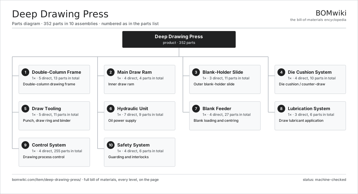
| # | Part | Qty | What it does |
|---|---|---|---|
| 1 | Double-Column Frame 5 parts | 1× | Double-column drawing frame |
| 2 | Main Draw Ram 4 parts | 1× | Inner draw ram |
| 3 | Blank-Holder Slide 3 parts | 1× | Outer blank-holder slide |
| 4 | Die Cushion System 4 parts | 1× | Die cushion / counter-draw |
| 5 | Draw Tooling 5 parts | 1× | Punch, draw ring and binder |
| 6 | Hydraulic Unit 7 parts | 1× | Oil power supply |
| 7 | Blank Feeder 4 parts | 1× | Blank loading and centring |
| 8 | Lubrication System 3 parts | 1× | Draw lubricant application |
| 9 | Control System 4 parts | 1× | Drawing process control |
| 10 | Safety System 4 parts | 1× | Guarding and interlocks |
3D model
No 3D model yet. Have a CAD file of this? Add a 3D model — STL renders right on this page; STEP, FreeCAD, and OpenSCAD sources are welcome too (openly licensed, like all 3D models on BOMwiki).
Build & assembly graph
expand / collapse · shared sub-assemblies converge · links to related products · est. labourTap an assembly to expand/collapse · tap a part to open it · use “Open page” for any node · drag to pan, scroll to zoom.
Bill of materials for Deep Drawing Press
10 top-level lines · 66 rows shown · 352 parts total · indented to 3 levels| # | Item / sub-assembly | Part no. | Qty/assy | Ext. qty | Parts | Type |
|---|---|---|---|---|---|---|
| 1 | Double-Column Frame 5 parts | ddp-frame | 1× | 1 | 13 | assembly |
| 1.1 | Frame Upright | ddp-frame-uprights | 2× | 2 | · | part |
| 1.2 | Crown | ddp-crown | 1× | 1 | · | part |
| 1.3 | Bed | ddp-bed | 1× | 1 | · | part |
| 1.4 | Slide Guideway | ddp-slide-guide | 8× | 8 | · | part |
| 1.5 | Fastener Set | fastener-set | 1× | 1 | · | part |
| 2 | Main Draw Ram 4 parts | ddp-main-ram | 1× | 1 | 4 | assembly |
| 2.1 | Draw Cylinder | ddp-draw-cylinder | 1× | 1 | · | part |
| 2.2 | Inner Slide | ddp-inner-slide | 1× | 1 | · | part |
| 2.3 | Stroke Sensor | ddp-stroke-sensor | 1× | 1 | · | part |
| 2.4 | Punch Mount | ddp-punch-mount | 1× | 1 | · | part |
| 3 | Blank-Holder Slide 3 parts | ddp-blank-holder | 1× | 1 | 11 | assembly |
| 3.1 | Blank-Holder Cylinder | ddp-holder-cylinder | 2× | 2 | · | part |
| 3.2 | Outer Slide | ddp-outer-slide | 1× | 1 | · | part |
| 3.3 | Pressure Pin | ddp-pressure-pins | 8× | 8 | · | part |
| 4 | Die Cushion System 4 parts | ddp-cushion-system | 1× | 1 | 10 | assembly |
| 4.1 | Cushion Cylinder | ddp-cushion-cylinder | 1× | 1 | · | part |
| 4.2 | Cushion Platen | ddp-cushion-platen | 1× | 1 | · | part |
| 4.3 | Ejector Pin | ddp-ejector-pins | 6× | 6 | · | part |
| 4.4 | Pressure Sensor | pressure-sensor | 2× | 2 | · | part |
| 5 | Draw Tooling 5 parts | ddp-draw-tooling | 1× | 1 | 11 | assembly |
| 5.1 | Draw Punch | ddp-draw-punch | 1× | 1 | · | part |
| 5.2 | Draw Ring | ddp-draw-ring | 1× | 1 | · | part |
| 5.3 | Binder Ring | ddp-binder-ring | 1× | 1 | · | part |
| 5.4 | Draw Bead | ddp-draw-bead | 4× | 4 | · | part |
| 5.5 | Ball Bearing | ball-bearing | 4× | 4 | · | part |
| 6 | Hydraulic Unit 7 parts | ddp-hydraulic-unit | 1× | 1 | 9 | assembly |
| 6.1 | Main Pump | ddp-pump | 1× | 1 | · | part |
| 6.2 | Pump Motor | ddp-pump-motor | 1× | 1 | · | part |
| 6.3 | Oil Reservoir | ddp-reservoir | 1× | 1 | · | part |
| 6.4 | Proportional Valve | ddp-proportional-valve | 3× | 3 | · | part |
| 6.5 | Relief Valve | ddp-relief-valve | 1× | 1 | · | part |
| 6.6 | Return Filter | ddp-filter | 1× | 1 | · | part |
| 6.7 | Oil Cooler | ddp-cooler | 1× | 1 | · | part |
| 7 | Blank Feeder 4 parts | ddp-blank-feeder | 1× | 1 | 27 | assembly |
| 7.1 | Blank De-Stacker | ddp-destacker | 1× | 1 | · | part |
| 7.2 | Feed Arm | ddp-feed-arm | 1× | 1 | · | part |
| 7.3 | Centring Station | ddp-centring-station | 1× | 1 | · | part |
| 7.4 | Servo Motor 4 parts | servo-motor | 1× | 1 | 24 | assembly |
| 7.4.1 | Stator Assembly 3 parts + deeper › | stator-assembly | 1× | 1 | 3 | assembly |
| 7.4.2 | Rotor Assembly 4 parts + deeper › | rotor-assembly | 1× | 1 | 19 | assembly |
| 7.4.3 | Encoder | encoder | 1× | 1 | · | part |
| 7.4.4 | Motor Housing | motor-housing | 1× | 1 | · | part |
| 8 | Lubrication System 3 parts | ddp-lubrication-system | 1× | 1 | 6 | assembly |
| 8.1 | Lubricant Pump | ddp-lube-pump | 1× | 1 | · | part |
| 8.2 | Lubricant Nozzle | ddp-lube-nozzle | 4× | 4 | · | part |
| 8.3 | Lubricant Tank | ddp-lube-tank | 1× | 1 | · | part |
| 9 | Control System 4 parts | ddp-control-system | 1× | 1 | 255 | assembly |
| 9.1 | CNC Controller 4 parts | ddp-cnc-controller | 1× | 1 | 159 | assembly |
| 9.1.1 | Bare PCB | pcb-bare | 1× | 1 | · | part |
| 9.1.2 | Microcontroller | mcu | 2× | 2 | · | part |
| 9.1.3 | Relay | relay | 6× | 6 | · | part |
| 9.1.4 | SMD Passive (R/C/L) | smd-passives | 150× | 150 | · | part |
| 9.2 | HMI Panel 5 parts | ddp-hmi | 1× | 1 | 94 | assembly |
| 9.2.1 | LCD Panel | lcd-panel | 1× | 1 | · | part |
| 9.2.2 | Touch Digitizer | touch-digitizer | 1× | 1 | · | part |
| 9.2.3 | Bare PCB | pcb-bare | 1× | 1 | · | part |
| 9.2.4 | Microcontroller | mcu | 1× | 1 | · | part |
| 9.2.5 | SMD Passive (R/C/L) | smd-passives | 90× | 90 | · | part |
| 9.3 | Power Supply | power-supply | 1× | 1 | · | part |
| 9.4 | Wire Bundle | wire-bundle | 1× | 1 | · | part |
| 10 | Safety System 4 parts | ddp-safety-system | 1× | 1 | 6 | assembly |
| 10.1 | Safety Light Curtain | ddp-light-curtain | 2× | 2 | · | part |
| 10.2 | Fixed Guard | ddp-fixed-guard | 1× | 1 | · | part |
| 10.3 | E-Stop | ddp-estop | 2× | 2 | · | part |
| 10.4 | Safety Relay | ddp-safety-relay | 1× | 1 | · | part |
Related products
same domain, ranked by shared parts Compression Spring Coiler
1,167 parts · shares 3 with this page
Gear Honing Machine
260 parts · shares 3 with this page
Compression Spring Coiler
1,167 parts · shares 3 with this page
Gear Honing Machine
260 parts · shares 3 with this page
 Servo Stamping Press
633 parts · shares 3 with this page
Servo Stamping Press
633 parts · shares 3 with this page
Sourcing: possible vendors
Prices, MOQ, and lead times are algorithmic estimates, not quotes, and not claims about these companies. Company mappings are curated by keyword; est. price band $10k–$1M. How estimates work| Vendor | HQ | Specialty | MOQ | Lead time |
|---|---|---|---|---|
|
🇩🇪DMG MORI
dmgmori.com ↗
|
Bielefeld, DE | Machine tools | 5 units | 12–20 wks |
|
🇯🇵Mazak
mazak.com ↗
|
Oguchi, JP | Machine tools | 5 units | 12–20 wks |
| haascnc.com ↗ | Oxnard, US | CNC machine tools | 5 units | 12–20 wks |
|
🇯🇵Okuma
okuma.com ↗
|
Niwa, JP | Machine tools | 5 units | 12–20 wks |
|
🇩🇪Trumpf
trumpf.com ↗
|
Ditzingen, DE | Laser & sheet-metal machines | 5 units | 12–20 wks |
974-word article