Servo Stamping Press
ProductOverview
A servo stamping press replaces the flywheel and clutch-brake of a mechanical press with a large servo motor under direct software control. The slide is no longer tied to a fixed crank rotation; instead the motor can drive it to any position, at any speed, with full force anywhere in the stroke, and it can stop, dwell, slow down, or reverse on command. That turns the press from a fixed-motion machine into a programmable one. One press can run a fast simple blanking profile on one job and a slow, dwelling deep-draw profile on the next, all by loading a different motion program.
The press keeps the rigid structure of a conventional machine, a stiff Press Frame and a guided Slide, but its drive, cushion, energy system and control are different. The motion comes from the Servo Drive Train, a Servo Die Cushion is itself servo-driven, an Energy Storage buffer handles the spiky power demand, a Feed System is synchronised to the programmed motion, and a Control System lets the operator build and store slide profiles. It sits between the speed of a Mechanical Power Press and the flexibility of a Hydraulic Punch Press, offering much of both.
Frame
The Press Frame is a straight-side design with two Frame Upright tied between the Crown and the Bed by pre-tensioned Tie Rod members, the same stiff arrangement used on a large mechanical press. Stiffness matters here because the servo press is often used for forming and coining at high force, and because the slide can dwell at the bottom of the stroke, holding load, which a flywheel press never does. The slide runs in adjustable Slide Gib guides kept tight, since the slide can reverse or hold anywhere and must stay square throughout.
Servo Drive Train
The Servo Drive Train is the heart of the machine. A high-torque Servo Drive Motor, often a direct-drive torque motor, is fed by a high-power Servo Amplifier and drives the slide through a Reduction Gear and an Eccentric Linkage. The eccentric still converts rotation to slide travel, but the servo can rotate it forward, hold it, or rock it back and forth, so the slide motion is whatever the program says. A high-resolution Crank Resolver closes the position loop. Because the motor delivers full torque at zero speed, the press makes full tonnage at the bottom of the stroke even while dwelling, which is what allows in-die coining and forming that a flywheel press cannot sustain.
Slide and Tooling
The Slide Body carries the upper die on a ground Slide Face, with a motorized Shut-Height Drive for die setup and a Hydraulic Overload Protector hydraulic cell guarding the drive train against a mis-set die. The Bolster and Tooling usually carries a multi-station Progressive Die Set for progressive work. The advantage of servo motion in a progressive die is that the slide can move quickly between stations and slow down precisely where a station is forming or drawing, raising the part rate without straining the difficult stations.
Servo Die Cushion
Where a mechanical press needs a separate pneumatic or hydraulic cushion, the servo press uses a Servo Die Cushion driven by its own Cushion Servo Motor through a Cushion Ball Screw. This gives a programmable blank-holder force that can be profiled through the stroke and synchronised with the slide, so the same press can do real deep drawing, normally the job of a Deep Drawing Press, by coordinating slide speed and cushion force exactly as the metal flow needs.
Energy Storage
A servo press has a spiky power demand: it draws a large burst during the brief forming hit and regenerates energy when it decelerates the slide. Drawing that straight from the grid would be inefficient and hard on the supply. The Energy Storage system smooths it. A Capacitor Bank buffers the peak forming power and absorbs the regenerated braking energy, a Regenerative Converter returns deceleration energy to the buffer or the line rather than burning it in a resistor, and a Energy Controller manages charge and discharge so the press presents a steady load to the grid. This recovery is a real efficiency gain over both flywheel and hydraulic presses.
Feed, Control and Safety
The Feed System is a servo coil feed timed to the programmed motion, advancing the strip during the slide dwell at top so feed and stroke never collide, with a Strip Pilot registering the strip before forming. The Control System runs on a Motion Controller that executes the stored slide profile and coordinates the servo, feed and cushion; the operator builds and saves these profiles on the Programming HMI. Safety benefits directly from the drive: because the Servo Drive Motor can be stopped or reversed almost immediately, the Safety System light curtain can sit closer to the die than on a flywheel press, and every channel ties into the safe-torque-off input of the servo amplifier through a monitored Safety Relay.
Variants and Use
Servo presses range from 80 ton units up to 2,000 ton machines for automotive body panels. Common motion modes include a standard stroke, a pendulum mode that rocks the slide over a short arc near bottom dead centre for very high stroke rates, a dwell mode that holds force for coining, and slow-forming modes for deep draws and thick material. They are widely used for electric-vehicle motor laminations, where the slow controlled cut keeps the thin silicon-steel sheet flat and burr-free, and for difficult formed parts that would need several different presses otherwise. The trade-offs against a Mechanical Power Press are higher cost and a more complex drive, paid back by one press doing the work of several and by recovered energy on every stroke.
Servo Stamping Press parts and their functions
10 top-level parts · 633 parts in total · full bill of materials below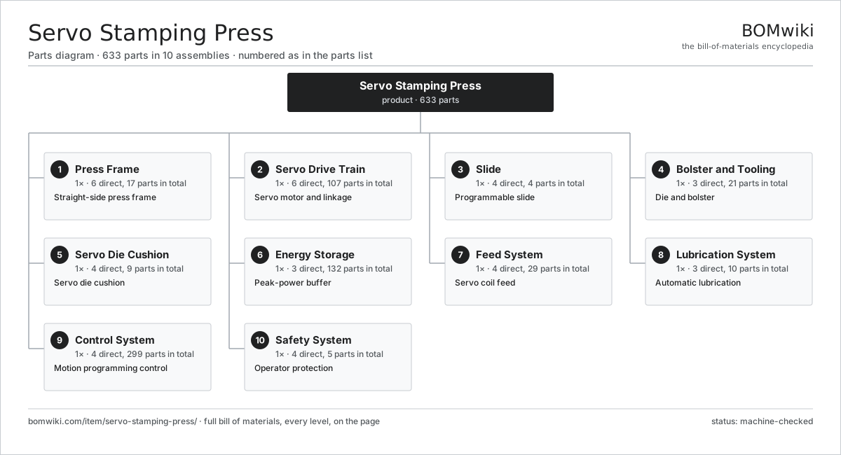
| # | Part | Qty | What it does |
|---|---|---|---|
| 1 | Press Frame 6 parts | 1× | Straight-side press frame |
| 2 | Servo Drive Train 6 parts | 1× | Servo motor and linkage |
| 3 | Slide 4 parts | 1× | Programmable slide |
| 4 | Bolster and Tooling 3 parts | 1× | Die and bolster |
| 5 | Servo Die Cushion 4 parts | 1× | Servo die cushion |
| 6 | Energy Storage 3 parts | 1× | Peak-power buffer |
| 7 | Feed System 4 parts | 1× | Servo coil feed |
| 8 | Lubrication System 3 parts | 1× | Automatic lubrication |
| 9 | Control System 4 parts | 1× | Motion programming control |
| 10 | Safety System 4 parts | 1× | Operator protection |
3D model
No 3D model yet. Have a CAD file of this? Add a 3D model — STL renders right on this page; STEP, FreeCAD, and OpenSCAD sources are welcome too (openly licensed, like all 3D models on BOMwiki).
Build & assembly graph
expand / collapse · shared sub-assemblies converge · links to related products · est. labourTap an assembly to expand/collapse · tap a part to open it · use “Open page” for any node · drag to pan, scroll to zoom.
Bill of materials for Servo Stamping Press
10 top-level lines · 79 rows shown · 633 parts total · indented to 3 levels| # | Item / sub-assembly | Part no. | Qty/assy | Ext. qty | Parts | Type |
|---|---|---|---|---|---|---|
| 1 | Press Frame 6 parts | ssp-frame | 1× | 1 | 17 | assembly |
| 1.1 | Frame Upright | ssp-frame-uprights | 2× | 2 | · | part |
| 1.2 | Crown | ssp-crown | 1× | 1 | · | part |
| 1.3 | Bed | ssp-bed | 1× | 1 | · | part |
| 1.4 | Tie Rod | ssp-tie-rod | 4× | 4 | · | part |
| 1.5 | Slide Gib | ssp-slide-gib | 8× | 8 | · | part |
| 1.6 | Fastener Set | fastener-set | 1× | 1 | · | part |
| 2 | Servo Drive Train 6 parts | ssp-servo-drive-train | 1× | 1 | 107 | assembly |
| 2.1 | Servo Drive Motor | ssp-servo-motor | 1× | 1 | · | part |
| 2.2 | Servo Amplifier 5 parts | ssp-servo-amplifier | 1× | 1 | 99 | assembly |
| 2.2.1 | Bare PCB | pcb-bare | 1× | 1 | · | part |
| 2.2.2 | IGBT Power Module | igbt-module | 6× | 6 | · | part |
| 2.2.3 | Gate Driver Board 3 parts + deeper › | gate-driver-board | 1× | 1 | 87 | assembly |
| 2.2.4 | DC-Link Capacitor | dc-link-cap | 4× | 4 | · | part |
| 2.2.5 | Microcontroller | mcu | 1× | 1 | · | part |
| 2.3 | Reduction Gear | ssp-reduction-gear | 1× | 1 | · | part |
| 2.4 | Eccentric Linkage | ssp-eccentric-linkage | 1× | 1 | · | part |
| 2.5 | Crank Resolver | ssp-resolver | 1× | 1 | · | part |
| 2.6 | Ball Bearing | ball-bearing | 4× | 4 | · | part |
| 3 | Slide 4 parts | ssp-slide | 1× | 1 | 4 | assembly |
| 3.1 | Slide Body | ssp-slide-body | 1× | 1 | · | part |
| 3.2 | Slide Face | ssp-slide-face | 1× | 1 | · | part |
| 3.3 | Shut-Height Drive | ssp-shut-height-adjust | 1× | 1 | · | part |
| 3.4 | Hydraulic Overload Protector | ssp-overload-protector | 1× | 1 | · | part |
| 4 | Bolster and Tooling 3 parts | ssp-bolster-tooling | 1× | 1 | 21 | assembly |
| 4.1 | Bolster Plate | ssp-bolster-plate | 1× | 1 | · | part |
| 4.2 | Progressive Die Set 5 parts | ssp-die-set | 1× | 1 | 16 | assembly |
| 4.2.1 | Die Punch | ssp-die-punch | 4× | 4 | · | part |
| 4.2.2 | Die Block | ssp-die-block | 1× | 1 | · | part |
| 4.2.3 | Die Stripper | ssp-die-stripper | 1× | 1 | · | part |
| 4.2.4 | Coil Spring | coil-spring | 6× | 6 | · | part |
| 4.2.5 | Ball Bearing | ball-bearing | 4× | 4 | · | part |
| 4.3 | Die Clamp | ssp-die-clamp | 4× | 4 | · | part |
| 5 | Servo Die Cushion 4 parts | ssp-die-cushion | 1× | 1 | 9 | assembly |
| 5.1 | Cushion Servo Motor | ssp-cushion-servo | 1× | 1 | · | part |
| 5.2 | Cushion Ball Screw | ssp-cushion-screw | 1× | 1 | · | part |
| 5.3 | Cushion Platen | ssp-cushion-platen | 1× | 1 | · | part |
| 5.4 | Cushion Pressure Pin | ssp-cushion-pins | 6× | 6 | · | part |
| 6 | Energy Storage 3 parts | ssp-energy-storage | 1× | 1 | 132 | assembly |
| 6.1 | Capacitor Bank | ssp-capacitor-bank | 1× | 1 | · | part |
| 6.2 | Energy Controller 4 parts | ssp-energy-controller | 1× | 1 | 130 | assembly |
| 6.2.1 | Bare PCB | pcb-bare | 1× | 1 | · | part |
| 6.2.2 | Microcontroller | mcu | 1× | 1 | · | part |
| 6.2.3 | Power MOSFET | mosfet | 8× | 8 | · | part |
| 6.2.4 | SMD Passive (R/C/L) | smd-passives | 120× | 120 | · | part |
| 6.3 | Regenerative Converter | ssp-regen-unit | 1× | 1 | · | part |
| 7 | Feed System 4 parts | ssp-feed-system | 1× | 1 | 29 | assembly |
| 7.1 | Feed Roll | ssp-feed-roll | 2× | 2 | · | part |
| 7.2 | Servo Motor 4 parts | servo-motor | 1× | 1 | 24 | assembly |
| 7.2.1 | Stator Assembly 3 parts + deeper › | stator-assembly | 1× | 1 | 3 | assembly |
| 7.2.2 | Rotor Assembly 4 parts + deeper › | rotor-assembly | 1× | 1 | 19 | assembly |
| 7.2.3 | Encoder | encoder | 1× | 1 | · | part |
| 7.2.4 | Motor Housing | motor-housing | 1× | 1 | · | part |
| 7.3 | Coil Straightener | ssp-straightener | 1× | 1 | · | part |
| 7.4 | Strip Pilot | ssp-pilot | 2× | 2 | · | part |
| 8 | Lubrication System 3 parts | ssp-lubrication-system | 1× | 1 | 10 | assembly |
| 8.1 | Lube Pump | ssp-lube-pump | 1× | 1 | · | part |
| 8.2 | Lube Manifold | ssp-lube-manifold | 1× | 1 | · | part |
| 8.3 | Lube Line | ssp-lube-line | 8× | 8 | · | part |
| 9 | Control System 4 parts | ssp-control-system | 1× | 1 | 299 | assembly |
| 9.1 | Motion Controller 5 parts | ssp-motion-controller | 1× | 1 | 193 | assembly |
| 9.1.1 | Bare PCB | pcb-bare | 1× | 1 | · | part |
| 9.1.2 | Microcontroller | mcu | 2× | 2 | · | part |
| 9.1.3 | Relay | relay | 8× | 8 | · | part |
| 9.1.4 | CAN Transceiver | can-transceiver | 2× | 2 | · | part |
| 9.1.5 | SMD Passive (R/C/L) | smd-passives | 180× | 180 | · | part |
| 9.2 | Programming HMI 5 parts | ssp-hmi | 1× | 1 | 104 | assembly |
| 9.2.1 | LCD Panel | lcd-panel | 1× | 1 | · | part |
| 9.2.2 | Touch Digitizer | touch-digitizer | 1× | 1 | · | part |
| 9.2.3 | Bare PCB | pcb-bare | 1× | 1 | · | part |
| 9.2.4 | Microcontroller | mcu | 1× | 1 | · | part |
| 9.2.5 | SMD Passive (R/C/L) | smd-passives | 100× | 100 | · | part |
| 9.3 | Power Supply | power-supply | 1× | 1 | · | part |
| 9.4 | Wire Bundle | wire-bundle | 1× | 1 | · | part |
| 10 | Safety System 4 parts | ssp-safety-system | 1× | 1 | 5 | assembly |
| 10.1 | Safety Light Curtain | ssp-light-curtain | 1× | 1 | · | part |
| 10.2 | Two-Hand Control | ssp-two-hand-control | 1× | 1 | · | part |
| 10.3 | E-Stop | ssp-estop | 2× | 2 | · | part |
| 10.4 | Safety Relay | ssp-safety-relay | 1× | 1 | · | part |
Related products
same domain, ranked by shared parts Compression Spring Coiler
1,167 parts · shares 8 with this page
Compression Spring Coiler
1,167 parts · shares 8 with this page
 Torsion Spring Coiler
1,148 parts · shares 8 with this page
Torsion Spring Coiler
1,148 parts · shares 8 with this page
Sourcing: possible vendors
Prices, MOQ, and lead times are algorithmic estimates, not quotes, and not claims about these companies. Company mappings are curated by keyword; est. price band $10k–$1M. How estimates work| Vendor | HQ | Specialty | MOQ | Lead time |
|---|---|---|---|---|
|
🇩🇪DMG MORI
dmgmori.com ↗
|
Bielefeld, DE | Machine tools | 5 units | 12–20 wks |
|
🇯🇵Mazak
mazak.com ↗
|
Oguchi, JP | Machine tools | 5 units | 12–20 wks |
| haascnc.com ↗ | Oxnard, US | CNC machine tools | 5 units | 12–20 wks |
|
🇯🇵Okuma
okuma.com ↗
|
Niwa, JP | Machine tools | 5 units | 12–20 wks |
|
🇩🇪Trumpf
trumpf.com ↗
|
Ditzingen, DE | Laser & sheet-metal machines | 5 units | 12–20 wks |
997-word article