Upsetter Forging Machine
ProductOverview
An upsetter forging machine, also called a horizontal forging machine or header, forms the end of a hot bar by gathering and compressing metal against a clamped length of stock. Unlike a vertical press, the upsetter works on a horizontal axis: a gripper holds the bar across its diameter while a horizontal ram drives a punch into the projecting heated end and upsets it. The machine makes bolt heads, flange ends, valve blanks, axle shafts, and similar parts where one end of a bar must carry much more metal than the shank. Because the gripper holds long stock that passes right through the dies, an upsetter can work on bar that is far longer than the machine, which a closed press cannot do. Header force ranges from about 100 t on small machines to 1600 t on the largest, at 30 to 90 strokes per minute.
How upsetting works
The heated bar end is pushed past the open gripper dies until it meets the Stock Stop, which sets how far the end projects and so fixes the volume of metal that will be gathered into the head. The Gripper Die Mechanism then clamps the bar: the Stationary Gripper Die holds the datum side and the Moving Gripper Die, carried on the Gripper Slide, closes from the other side. With the bar held, the Heading Slide drives a Heading Punch axially into the projecting end and upsets it. A long projection cannot be headed in one blow because the unsupported metal would buckle, so the work runs across two to four passes. The Coning Tool gathers and cones the end first, later punches build the bulk, and the final punch forms the head profile. Between passes the Tool Index Slide indexes the punch block so the bar meets each tool in turn, and after the last pass the Kick-Out Pin ejects the finished part.
Heading slide and drive
The Heading Slide is driven by the Crankshaft through an Eccentric and a Connecting Rod joined to the Header Ram by a hardened Wrist Pin. The eccentric throw sets the maximum stroke, and the Stroke Adjuster sets the shut height so the punch reaches the bar at the right point of travel. The ram slides on Ram Gib strips that keep the punch centred on the gripped bar. Energy comes from the Main Drive, where a Main Drive Motor of 30 to 250 kW keeps a heavy Flywheel spinning between strokes. The Clutch-Brake Unit couples the flywheel to the crankshaft for a single stroke on demand and stops the crank at top of stroke. The motor only restores the speed the flywheel loses, so it can be far smaller than the peak heading power. Drive runs through a Drive Belt set, a Drive Pinion, and a Helical Gear Pair in a Gearbox Housing, with an Encoder reporting crank angle.
Gripper timing
Clamping must lead the heading stroke, because the dies have to hold the bar before the punch arrives and must not release until the upset is finished. The Gripper Cam Linkage sets this timing. A Gripper Cam on the crankshaft drives a Cam Follower and a Rocker Lever that pushes the gripper slide, and a Toggle Link goes near dead centre as the dies close so a modest cam force produces the high clamp load that resists the upset force. A Lock Wedge takes up slide clearance so the dies do not back off under load, and Coil Spring elements return the follower onto the cam. The dies sit in a Die Holder that can be changed for a different bar diameter.
Tooling, hydraulics, and cooling
The Heading Tooling block carries the punches in a Punch Holder and reacts the axial load through a Backstop Block. Hot upsetting is hard on tools, so the Lubrication and Die Cooling system sprays graphite release agent from a Spray Header onto the dies and punches between strokes, metered by a Lubricant Pump from an agitated Lubricant Mix Tank. The Oil Circuit feeds the crankshaft bearings, ram gibs, and gripper slide, and the Scale Blow-Off clears furnace scale off the bar before heading. The Hydraulic Power Unit supplies the gripper boost and kick-out cylinders: a Hydraulic Pump gives 160 to 250 bar, a Valve Manifold sequences the motions, an Accumulator steadies clamp pressure, and a Oil Cooler holds oil temperature down near the hot dies. A Pressure Sensor confirms grip pressure each stroke.
Control, frame, and materials
The Control Cabinet cabinet houses a PLC Control that ties clutch engagement, gripper close, spray, and kick-out to crank angle, with a Operator HMI holding stroke rate, pass settings, and counts per part number. A Drive Module feeds the motor through an IGBT Power Module stage and a Power Supply, wired by a Wire Bundle to a Connector panel and switched by a Relay bank. The whole machine sits on the Machine Frame, a heavy Main Frame casting pulled together by a Tie Rod set so the heading force is carried in tension. Gripper dies and punches are H13 or 5CrNiMo hot-work tool steel hardened to resist heat and abrasion, the crankshaft and connecting rod are forged 42CrMo4, and bars enter at 1050 to 1250 deg C for carbon and alloy steels. An upsetter is often the head-forming station on a line that feeds bolt, axle, and valve production where one end of a long bar must gather far more metal than the shank.
Upsetter Forging Machine parts and their functions
9 top-level parts · 125 parts in total · full bill of materials below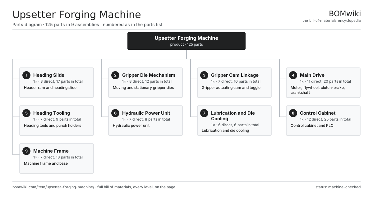
| # | Part | Qty | What it does |
|---|---|---|---|
| 1 | Heading Slide 8 parts | 1× | Header ram and heading slide |
| 2 | Gripper Die Mechanism 8 parts | 1× | Moving and stationary gripper dies |
| 3 | Gripper Cam Linkage 7 parts | 1× | Gripper actuating cam and toggle |
| 4 | Main Drive 11 parts | 1× | Motor, flywheel, clutch-brake, crankshaft |
| 5 | Heading Tooling 7 parts | 1× | Heading tools and punch holders |
| 6 | Hydraulic Power Unit 7 parts | 1× | Hydraulic power unit |
| 7 | Lubrication and Die Cooling 6 parts | 1× | Lubrication and die cooling |
| 8 | Control Cabinet 12 parts | 1× | Control cabinet and PLC |
| 9 | Machine Frame 7 parts | 1× | Machine frame and base |
3D model
No 3D model yet. Have a CAD file of this? Add a 3D model — STL renders right on this page; STEP, FreeCAD, and OpenSCAD sources are welcome too (openly licensed, like all 3D models on BOMwiki).
Build & assembly graph
expand / collapse · shared sub-assemblies converge · links to related products · est. labourTap an assembly to expand/collapse · tap a part to open it · use “Open page” for any node · drag to pan, scroll to zoom.
Bill of materials for Upsetter Forging Machine
9 top-level lines · 82 rows shown · 125 parts total · indented to 3 levels| # | Item / sub-assembly | Part no. | Qty/assy | Ext. qty | Parts | Type |
|---|---|---|---|---|---|---|
| 1 | Heading Slide 8 parts | upsetter-forging-machine-heading-slide | 1× | 1 | 17 | assembly |
| 1.1 | Header Ram | upsetter-forging-machine-header-ram | 1× | 1 | · | part |
| 1.2 | Ram Gib | upsetter-forging-machine-ram-gib | 4× | 4 | · | part |
| 1.3 | Connecting Rod | upsetter-forging-machine-connecting-rod | 1× | 1 | · | part |
| 1.4 | Eccentric | upsetter-forging-machine-eccentric | 1× | 1 | · | part |
| 1.5 | Wrist Pin | upsetter-forging-machine-wrist-pin | 1× | 1 | · | part |
| 1.6 | Stroke Adjuster | upsetter-forging-machine-stroke-adjuster | 1× | 1 | · | part |
| 1.7 | Ball Bearing | ball-bearing | 4× | 4 | · | part |
| 1.8 | Oil Seal | oil-seal | 4× | 4 | · | part |
| 2 | Gripper Die Mechanism 8 parts | upsetter-forging-machine-gripper-die-mechanism | 1× | 1 | 12 | assembly |
| 2.1 | Stationary Gripper Die | upsetter-forging-machine-stationary-die | 1× | 1 | · | part |
| 2.2 | Moving Gripper Die | upsetter-forging-machine-moving-die | 1× | 1 | · | part |
| 2.3 | Gripper Slide | upsetter-forging-machine-gripper-slide | 1× | 1 | · | part |
| 2.4 | Die Holder | upsetter-forging-machine-die-holder | 2× | 2 | · | part |
| 2.5 | Kick-Out Pin | upsetter-forging-machine-kickout-pin | 2× | 2 | · | part |
| 2.6 | Stock Stop | upsetter-forging-machine-stock-stop | 1× | 1 | · | part |
| 2.7 | Ball Bearing | ball-bearing | 2× | 2 | · | part |
| 2.8 | Oil Seal | oil-seal | 2× | 2 | · | part |
| 3 | Gripper Cam Linkage 7 parts | upsetter-forging-machine-gripper-cam-linkage | 1× | 1 | 10 | assembly |
| 3.1 | Gripper Cam | upsetter-forging-machine-gripper-cam | 1× | 1 | · | part |
| 3.2 | Toggle Link | upsetter-forging-machine-toggle-link | 1× | 1 | · | part |
| 3.3 | Cam Follower | upsetter-forging-machine-cam-follower | 1× | 1 | · | part |
| 3.4 | Rocker Lever | upsetter-forging-machine-rocker-lever | 1× | 1 | · | part |
| 3.5 | Lock Wedge | upsetter-forging-machine-gib-wedge | 2× | 2 | · | part |
| 3.6 | Coil Spring | coil-spring | 2× | 2 | · | part |
| 3.7 | Ball Bearing | ball-bearing | 2× | 2 | · | part |
| 4 | Main Drive 11 parts | upsetter-forging-machine-main-drive | 1× | 1 | 20 | assembly |
| 4.1 | Main Drive Motor | upsetter-forging-machine-main-motor | 1× | 1 | · | part |
| 4.2 | Flywheel | upsetter-forging-machine-flywheel | 1× | 1 | · | part |
| 4.3 | Clutch-Brake Unit | upsetter-forging-machine-clutch-brake | 1× | 1 | · | part |
| 4.4 | Crankshaft | upsetter-forging-machine-crankshaft | 1× | 1 | · | part |
| 4.5 | Drive Pinion | upsetter-forging-machine-pinion-gear | 1× | 1 | · | part |
| 4.6 | Drive Belt | drive-belt | 4× | 4 | · | part |
| 4.7 | Helical Gear Pair | gear-pair | 1× | 1 | · | part |
| 4.8 | Gearbox Housing | gearbox-housing | 1× | 1 | · | part |
| 4.9 | Ball Bearing | ball-bearing | 4× | 4 | · | part |
| 4.10 | Oil Seal | oil-seal | 4× | 4 | · | part |
| 4.11 | Encoder | encoder | 1× | 1 | · | part |
| 5 | Heading Tooling 7 parts | upsetter-forging-machine-tooling | 1× | 1 | 9 | assembly |
| 5.1 | Heading Punch | upsetter-forging-machine-heading-punch | 3× | 3 | · | part |
| 5.2 | Punch Holder | upsetter-forging-machine-punch-holder | 1× | 1 | · | part |
| 5.3 | Coning Tool | upsetter-forging-machine-coning-tool | 1× | 1 | · | part |
| 5.4 | Tool Index Slide | upsetter-forging-machine-tool-slide | 1× | 1 | · | part |
| 5.5 | Backstop Block | upsetter-forging-machine-backstop-block | 1× | 1 | · | part |
| 5.6 | Fastener Set | fastener-set | 1× | 1 | · | part |
| 5.7 | O-Ring Set | oring-set | 1× | 1 | · | part |
| 6 | Hydraulic Power Unit 7 parts | upsetter-forging-machine-hpu | 1× | 1 | 8 | assembly |
| 6.1 | Hydraulic Pump | upsetter-forging-machine-hyd-pump | 1× | 1 | · | part |
| 6.2 | Oil Reservoir | upsetter-forging-machine-hyd-tank | 1× | 1 | · | part |
| 6.3 | Valve Manifold | upsetter-forging-machine-hyd-manifold | 1× | 1 | · | part |
| 6.4 | Accumulator | upsetter-forging-machine-accumulator | 1× | 1 | · | part |
| 6.5 | Oil Cooler | upsetter-forging-machine-hyd-cooler | 1× | 1 | · | part |
| 6.6 | Pressure Sensor | pressure-sensor | 2× | 2 | · | part |
| 6.7 | O-Ring Set | oring-set | 1× | 1 | · | part |
| 7 | Lubrication and Die Cooling 6 parts | upsetter-forging-machine-lubrication | 1× | 1 | 6 | assembly |
| 7.1 | Spray Header | upsetter-forging-machine-spray-header | 1× | 1 | · | part |
| 7.2 | Lubricant Pump | upsetter-forging-machine-spray-pump | 1× | 1 | · | part |
| 7.3 | Lubricant Mix Tank | upsetter-forging-machine-lube-tank | 1× | 1 | · | part |
| 7.4 | Oil Circuit | upsetter-forging-machine-oil-circuit | 1× | 1 | · | part |
| 7.5 | Scale Blow-Off | upsetter-forging-machine-scale-blowoff | 1× | 1 | · | part |
| 7.6 | Pressure Sensor | pressure-sensor | 1× | 1 | · | part |
| 8 | Control Cabinet 12 parts | upsetter-forging-machine-controls | 1× | 1 | 25 | assembly |
| 8.1 | PLC Control | upsetter-forging-machine-plc | 1× | 1 | · | part |
| 8.2 | Operator HMI | upsetter-forging-machine-hmi | 1× | 1 | · | part |
| 8.3 | Drive Module | upsetter-forging-machine-drive-module | 1× | 1 | · | part |
| 8.4 | Power Supply | power-supply | 1× | 1 | · | part |
| 8.5 | IGBT Power Module | igbt-module | 2× | 2 | · | part |
| 8.6 | Relay | relay | 6× | 6 | · | part |
| 8.7 | Bare PCB | pcb-bare | 1× | 1 | · | part |
| 8.8 | Microcontroller | mcu | 1× | 1 | · | part |
| 8.9 | SMD Passive (R/C/L) | smd-passives | 1× | 1 | · | part |
| 8.10 | Connector | connector | 8× | 8 | · | part |
| 8.11 | Wire Bundle | wire-bundle | 1× | 1 | · | part |
| 8.12 | LCD Panel | lcd-panel | 1× | 1 | · | part |
| 9 | Machine Frame 7 parts | upsetter-forging-machine-frame | 1× | 1 | 18 | assembly |
| 9.1 | Main Frame | upsetter-forging-machine-main-frame | 1× | 1 | · | part |
| 9.2 | Tie Rod | upsetter-forging-machine-tie-rod | 4× | 4 | · | part |
| 9.3 | Scale Chute | upsetter-forging-machine-scale-chute | 1× | 1 | · | part |
| 9.4 | Guard Panels | upsetter-forging-machine-guard-panels | 1× | 1 | · | part |
| 9.5 | Leveling Mount | upsetter-forging-machine-leveling | 6× | 6 | · | part |
| 9.6 | Sheet Metal Panel | sheet-panel | 4× | 4 | · | part |
| 9.7 | Fastener Set | fastener-set | 1× | 1 | · | part |
Related products
same domain, ranked by shared parts Rotary-Table Surface Grinder
172 parts · shares 8 with this page
Spline Rolling Machine
138 parts · shares 8 with this page
Rotary-Table Surface Grinder
172 parts · shares 8 with this page
Spline Rolling Machine
138 parts · shares 8 with this page
 Bevel Gear Generator
201 parts · shares 7 with this page
Bevel Gear Generator
201 parts · shares 7 with this page
 Forging Trim Press
190 parts · shares 7 with this page
Centering and Facing Machine
1,419 parts · shares 7 with this page
Forging Roll Machine
135 parts · shares 7 with this page
Forging Trim Press
190 parts · shares 7 with this page
Centering and Facing Machine
1,419 parts · shares 7 with this page
Forging Roll Machine
135 parts · shares 7 with this page
Sourcing: possible vendors
Prices, MOQ, and lead times are algorithmic estimates, not quotes, and not claims about these companies. Company mappings are curated by keyword; est. price band $10k–$1M. How estimates work| Vendor | HQ | Specialty | MOQ | Lead time |
|---|---|---|---|---|
|
🇩🇪DMG MORI
dmgmori.com ↗
|
Bielefeld, DE | Machine tools | 5 units | 12–20 wks |
|
🇯🇵Mazak
mazak.com ↗
|
Oguchi, JP | Machine tools | 5 units | 12–20 wks |
| haascnc.com ↗ | Oxnard, US | CNC machine tools | 5 units | 12–20 wks |
|
🇯🇵Okuma
okuma.com ↗
|
Niwa, JP | Machine tools | 5 units | 12–20 wks |
|
🇩🇪Trumpf
trumpf.com ↗
|
Ditzingen, DE | Laser & sheet-metal machines | 5 units | 12–20 wks |
1,046-word article