Plate Shear
ProductOverview
A plate shear cuts thick steel plate to length by forcing a long upper blade down past a fixed lower blade, the same action as a paper guillotine scaled up to cut steel up to roughly 25 to 40 mm thick. The Cutting Beam carries the Upper Blade down through the plate while the Lower Blade sits in the Lower Table (Bed). Where a light sheet shear works with gauge stock and quick strokes, this machine is built for mass: a heavy Machine Frame, two large Main Cutting Cylinder units, a high-pressure Hydraulic Power Unit, and a long, thick blade set that can take the break-through shock of cutting structural plate. The whole machine often weighs 30 to 80 tonnes because that mass is what keeps the cut straight when the plate fights back.
Frame and cutting beam
The Machine Frame reacts the entire cutting load. Two thick Side Housing plates carry the beam and cylinders, tied together by the Lower Table (Bed) and the Cross Tie Beam members so the structure barely flexes under load. Frame deflection shows up directly as a wedged or tapered cut, so on a heavy plate machine the side housings are far thicker than anything a sheet shear needs. The Cutting Beam is a box-section Beam Weldment running in bronze-faced Beam Guide Gib guides. Its stroke is set by the Stroke Limiter, and the Beam Return Spring units lift it clear after each cut.
Blades, rake, and gap
Cutting force depends on plate thickness, plate strength, and how much blade meets the plate at once. To keep that force manageable on thick plate, the upper blade is set at a shallow shear angle by the Rake Angle Adjuster, typically 2 to 3 degrees. The rake means the cut starts at one end and travels along the plate, so only a short length is being sheared at any instant. A larger rake cuts thicker plate with less force but twists and bows the strip more, so the operator trades cut quality against capacity by setting the angle for the job. The Blade Gap Adjuster sets the clearance between the Upper Blade and Lower Blade; thick plate needs a wider gap, around 7 to 10 percent of thickness, while a gap that is too tight drags the edges and wears the blades fast. Both the upper and lower blades have four usable cutting edges, so a dull edge is rotated rather than reground, and they are clamped to their seats by the Blade Clamp Bolt set with Blade Shim packs trimming height and gap. Hardened tool-steel blades on a heavy shear give long edge life because the machine has the mass to hold them aligned.
Hydraulic power
The Hydraulic Power Unit supplies the force. A Main Hydraulic Pump driven by the Pump Drive Motor pulls oil from the Hydraulic Oil Tank and feeds the Valve Manifold Block, which routes pressure to the two main cylinders and to the clamps. The Pressure Relief Valve sets the working pressure near 250 bar, and the Hydraulic Accumulator absorbs the sharp pressure drop when the plate breaks through, which protects the system from the recoil that a heavy cut produces. An Oil Cooler holds oil temperature on long runs, and the Return Line Filter keeps the oil clean enough for the Proportional Flow Valve to meter the beam smoothly. Each Main Cutting Cylinder uses a chrome-plated Cylinder Piston Rod in a honed Cylinder Tube with a full Cylinder Seal Kit.
Hold-down and gauging
Thick plate will lift and kick as the blade enters, so the Hold-Down System pins it first. A bank of fourteen Hold-Down Cylinder units presses Hold-Down Foot Pad pads down across the full bed length, spreading the clamping load so the plate cannot shift. Cut length is set by the Back Gauge, a servo-driven Ball Screw axis on Linear Guide Rail rails carrying a heavy Back Gauge Stop Bar with adjustable Back Gauge Finger stops; the Back Gauge Encoder closes the loop for repeatable lengths. At the front, the Ball Transfer Table lets an operator slide a heavy plate without lifting it, and the Squaring Arm and Side Gauge register the plate square to the blade. On a machine cutting plate this heavy, the front Front Support Arm units swing out to catch the off-cut so a large drop does not bend the strip or strike the operator.
Control and safety
The Control System runs the cut sequence from the CNC Control Board, with the Operator Touchscreen taking length, thickness, and gap settings and a Servo Driver positioning the back gauge. Because the blade and the clamps can both crush, the Safety Guarding adds a Front Finger Guard, a Rear Guard, a Safety Light Curtain, and several Emergency Stop Button buttons, and the Foot Pedal is a hold-to-run control so the stroke stops the moment it is released.
Plate Shear parts and their functions
10 top-level parts · 679 parts in total · full bill of materials below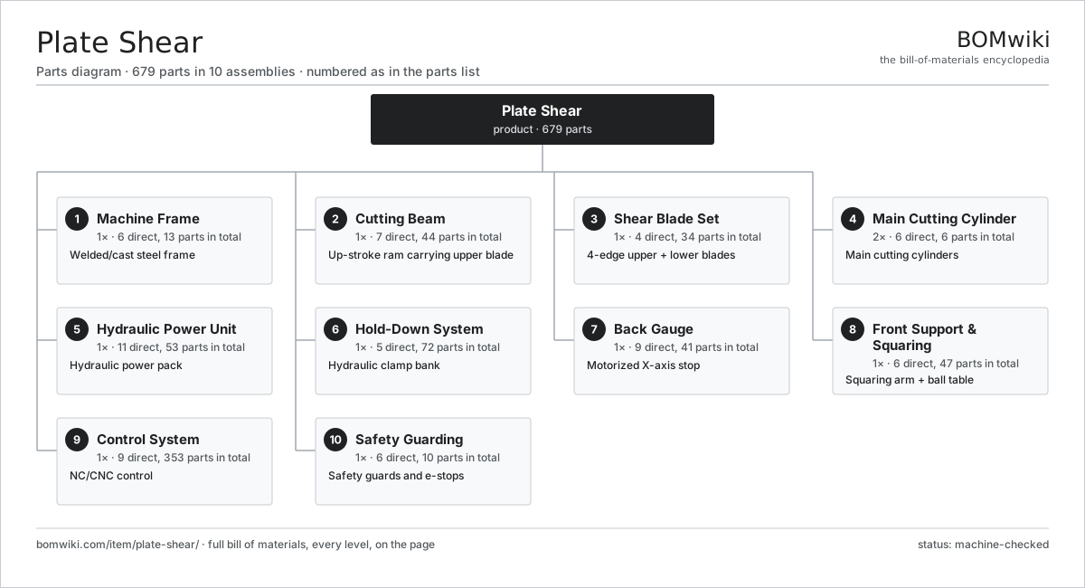
| # | Part | Qty | What it does |
|---|---|---|---|
| 1 | Machine Frame 6 parts | 1× | Welded/cast steel frame |
| 2 | Cutting Beam 7 parts | 1× | Up-stroke ram carrying upper blade |
| 3 | Shear Blade Set 4 parts | 1× | 4-edge upper + lower blades |
| 4 | Main Cutting Cylinder 6 parts | 2× | Main cutting cylinders |
| 5 | Hydraulic Power Unit 11 parts | 1× | Hydraulic power pack |
| 6 | Hold-Down System 5 parts | 1× | Hydraulic clamp bank |
| 7 | Back Gauge 9 parts | 1× | Motorized X-axis stop |
| 8 | Front Support & Squaring 6 parts | 1× | Squaring arm + ball table |
| 9 | Control System 9 parts | 1× | NC/CNC control |
| 10 | Safety Guarding 6 parts | 1× | Safety guards and e-stops |
3D model
No 3D model yet. Have a CAD file of this? Add a 3D model — STL renders right on this page; STEP, FreeCAD, and OpenSCAD sources are welcome too (openly licensed, like all 3D models on BOMwiki).
Build & assembly graph
expand / collapse · shared sub-assemblies converge · links to related products · est. labourTap an assembly to expand/collapse · tap a part to open it · use “Open page” for any node · drag to pan, scroll to zoom.
Bill of materials for Plate Shear
10 top-level lines · 129 rows shown · 679 parts total · indented to 3 levels| # | Item / sub-assembly | Part no. | Qty/assy | Ext. qty | Parts | Type |
|---|---|---|---|---|---|---|
| 1 | Machine Frame 6 parts | plate-shear-frame | 1× | 1 | 13 | assembly |
| 1.1 | Side Housing | plate-shear-side-housing | 2× | 2 | · | part |
| 1.2 | Lower Table (Bed) | plate-shear-bed | 1× | 1 | · | part |
| 1.3 | Cross Tie Beam | plate-shear-cross-tie | 2× | 2 | · | part |
| 1.4 | Bed Blade Seat | plate-shear-bed-blade-seat | 1× | 1 | · | part |
| 1.5 | Leveling Pad | plate-shear-leveling-pad | 6× | 6 | · | part |
| 1.6 | Fastener Set | fastener-set | 1× | 1 | · | part |
| 2 | Cutting Beam 7 parts | plate-shear-cutting-beam | 1× | 1 | 44 | assembly |
| 2.1 | Beam Weldment | plate-shear-beam-weldment | 1× | 1 | · | part |
| 2.2 | Beam Guide Gib | plate-shear-beam-gib | 4× | 4 | · | part |
| 2.3 | Rake Angle Adjuster 4 parts | plate-shear-rake-adjuster | 1× | 1 | 29 | assembly |
| 2.3.1 | Rake Adjust Screw | plate-shear-rake-screw | 2× | 2 | · | part |
| 2.3.2 | Rake Wedge Block | plate-shear-rake-wedge | 2× | 2 | · | part |
| 2.3.3 | Helical Gear Pair | gear-pair | 1× | 1 | · | part |
| 2.3.4 | Servo Motor 4 parts + deeper › | servo-motor | 1× | 1 | 24 | assembly |
| 2.4 | Blade Gap Adjuster 3 parts | plate-shear-blade-gap-adjuster | 1× | 1 | 4 | assembly |
| 2.4.1 | Gap Eccentric Bushing | plate-shear-gap-eccentric | 2× | 2 | · | part |
| 2.4.2 | Gap Setting Handwheel | plate-shear-gap-handwheel | 1× | 1 | · | part |
| 2.4.3 | Helical Gear Pair | gear-pair | 1× | 1 | · | part |
| 2.5 | Stroke Limiter | plate-shear-stroke-limiter | 1× | 1 | · | part |
| 2.6 | Beam Return Spring | plate-shear-beam-return-spring | 4× | 4 | · | part |
| 2.7 | Fastener Set | fastener-set | 1× | 1 | · | part |
| 3 | Shear Blade Set 4 parts | plate-shear-blade-set | 1× | 1 | 34 | assembly |
| 3.1 | Upper Blade | plate-shear-upper-blade | 1× | 1 | · | part |
| 3.2 | Lower Blade | plate-shear-lower-blade | 1× | 1 | · | part |
| 3.3 | Blade Clamp Bolt | plate-shear-blade-clamp-bolt | 24× | 24 | · | part |
| 3.4 | Blade Shim | plate-shear-blade-shim | 8× | 8 | · | part |
| 4 | Main Cutting Cylinder 6 parts | plate-shear-cylinder | 2× | 2 | 6 | assembly |
| 4.1 | Cylinder Tube | plate-shear-cylinder-tube | 1× | 2 | · | part |
| 4.2 | Cylinder Piston Rod | plate-shear-piston-rod | 1× | 2 | · | part |
| 4.3 | Cylinder Piston | plate-shear-cylinder-piston | 1× | 2 | · | part |
| 4.4 | Cylinder Gland | plate-shear-cylinder-gland | 1× | 2 | · | part |
| 4.5 | Cylinder Seal Kit | plate-shear-seal-kit | 1× | 2 | · | part |
| 4.6 | O-Ring Set | oring-set | 1× | 2 | · | part |
| 5 | Hydraulic Power Unit 11 parts | plate-shear-power-unit | 1× | 1 | 53 | assembly |
| 5.1 | Hydraulic Oil Tank 3 parts | plate-shear-oil-tank | 1× | 1 | 3 | assembly |
| 5.1.1 | Tank Weldment | plate-shear-tank-weldment | 1× | 1 | · | part |
| 5.1.2 | Oil Level Gauge | plate-shear-level-gauge | 1× | 1 | · | part |
| 5.1.3 | Tank Breather/Filler | plate-shear-tank-breather | 1× | 1 | · | part |
| 5.2 | Main Hydraulic Pump 5 parts | plate-shear-main-pump | 1× | 1 | 6 | assembly |
| 5.2.1 | Pump Housing | plate-shear-pump-housing | 1× | 1 | · | part |
| 5.2.2 | Pump Rotating Group | plate-shear-pump-rotating-group | 1× | 1 | · | part |
| 5.2.3 | Ball Bearing | ball-bearing | 2× | 2 | · | part |
| 5.2.4 | Oil Seal | oil-seal | 1× | 1 | · | part |
| 5.2.5 | O-Ring Set | oring-set | 1× | 1 | · | part |
| 5.3 | Pump Drive Motor 5 parts | plate-shear-pump-motor | 1× | 1 | 26 | assembly |
| 5.3.1 | Stator Assembly 3 parts + deeper › | stator-assembly | 1× | 1 | 3 | assembly |
| 5.3.2 | Rotor Assembly 4 parts + deeper › | rotor-assembly | 1× | 1 | 19 | assembly |
| 5.3.3 | Motor Frame | plate-shear-motor-frame | 1× | 1 | · | part |
| 5.3.4 | Ball Bearing | ball-bearing | 2× | 2 | · | part |
| 5.3.5 | Motor Cooling Fan | plate-shear-cooling-fan | 1× | 1 | · | part |
| 5.4 | Valve Manifold Block 5 parts | plate-shear-valve-block | 1× | 1 | 8 | assembly |
| 5.4.1 | Manifold Body | plate-shear-manifold-body | 1× | 1 | · | part |
| 5.4.2 | Directional Control Valve | plate-shear-directional-valve | 2× | 2 | · | part |
| 5.4.3 | Proportional Flow Valve | plate-shear-proportional-valve | 1× | 1 | · | part |
| 5.4.4 | Check Valve | plate-shear-check-valve | 3× | 3 | · | part |
| 5.4.5 | O-Ring Set | oring-set | 1× | 1 | · | part |
| 5.5 | Pressure Relief Valve | plate-shear-relief-valve | 2× | 2 | · | part |
| 5.6 | Hydraulic Accumulator | plate-shear-accumulator | 1× | 1 | · | part |
| 5.7 | Return Line Filter | plate-shear-return-filter | 1× | 1 | · | part |
| 5.8 | Suction Strainer | plate-shear-suction-strainer | 1× | 1 | · | part |
| 5.9 | Oil Cooler 2 parts | plate-shear-oil-cooler | 1× | 1 | 2 | assembly |
| 5.9.1 | Cooler Core | plate-shear-cooler-core | 1× | 1 | · | part |
| 5.9.2 | Cooler Fan | plate-shear-cooler-fan | 1× | 1 | · | part |
| 5.10 | Hydraulic Hose Set | plate-shear-hose-set | 1× | 1 | · | part |
| 5.11 | Pressure Sensor | pressure-sensor | 2× | 2 | · | part |
| 6 | Hold-Down System 5 parts | plate-shear-holddown-system | 1× | 1 | 72 | assembly |
| 6.1 | Hold-Down Cylinder 3 parts | plate-shear-holddown-cylinder | 14× | 14 | 3 | assembly |
| 6.1.1 | Hold-Down Cylinder Body | plate-shear-holddown-tube | 1× | 14 | · | part |
| 6.1.2 | Hold-Down Piston | plate-shear-holddown-piston | 1× | 14 | · | part |
| 6.1.3 | Cylinder Seal Kit | plate-shear-seal-kit | 1× | 14 | · | part |
| 6.2 | Hold-Down Foot Pad | plate-shear-holddown-foot | 14× | 14 | · | part |
| 6.3 | Hold-Down Return Spring | plate-shear-holddown-return-spring | 14× | 14 | · | part |
| 6.4 | Hold-Down Rail | plate-shear-holddown-rail | 1× | 1 | · | part |
| 6.5 | Hydraulic Hose Set | plate-shear-hose-set | 1× | 1 | · | part |
| 7 | Back Gauge 9 parts | plate-shear-back-gauge | 1× | 1 | 41 | assembly |
| 7.1 | Ball Screw | ball-screw | 1× | 1 | · | part |
| 7.2 | Linear Guide Rail | linear-guide | 2× | 2 | · | part |
| 7.3 | Servo Motor 4 parts | servo-motor | 1× | 1 | 24 | assembly |
| 7.3.1 | Stator Assembly 3 parts + deeper › | stator-assembly | 1× | 1 | 3 | assembly |
| 7.3.2 | Rotor Assembly 4 parts + deeper › | rotor-assembly | 1× | 1 | 19 | assembly |
| 7.3.3 | Encoder | encoder | 1× | 1 | · | part |
| 7.3.4 | Motor Housing | motor-housing | 1× | 1 | · | part |
| 7.4 | Gearbox Housing | gearbox-housing | 1× | 1 | · | part |
| 7.5 | Back Gauge Stop Bar | plate-shear-gauge-bar | 1× | 1 | · | part |
| 7.6 | Back Gauge Finger | plate-shear-gauge-finger | 6× | 6 | · | part |
| 7.7 | Back Gauge Encoder | plate-shear-gauge-encoder | 1× | 1 | · | part |
| 7.8 | Ball Bearing | ball-bearing | 4× | 4 | · | part |
| 7.9 | Fastener Set | fastener-set | 1× | 1 | · | part |
| 8 | Front Support & Squaring 6 parts | plate-shear-front-support | 1× | 1 | 47 | assembly |
| 8.1 | Ball Transfer Table 2 parts | plate-shear-ball-table | 1× | 1 | 41 | assembly |
| 8.1.1 | Ball Transfer Unit | plate-shear-ball-transfer | 40× | 40 | · | part |
| 8.1.2 | Ball Table Frame | plate-shear-table-frame | 1× | 1 | · | part |
| 8.2 | Front Support Arm | plate-shear-support-arm | 2× | 2 | · | part |
| 8.3 | Squaring Arm | plate-shear-squaring-arm | 1× | 1 | · | part |
| 8.4 | Side Gauge | plate-shear-side-gauge | 1× | 1 | · | part |
| 8.5 | Squaring Scale Tape | plate-shear-scale-tape | 1× | 1 | · | part |
| 8.6 | Fastener Set | fastener-set | 1× | 1 | · | part |
| 9 | Control System 9 parts | plate-shear-control-system | 1× | 1 | 353 | assembly |
| 9.1 | CNC Control Board 4 parts | plate-shear-control-board | 1× | 1 | 154 | assembly |
| 9.1.1 | Bare PCB | pcb-bare | 1× | 1 | · | part |
| 9.1.2 | Microcontroller | mcu | 1× | 1 | · | part |
| 9.1.3 | SMD Passive (R/C/L) | smd-passives | 140× | 140 | · | part |
| 9.1.4 | Connector | connector | 12× | 12 | · | part |
| 9.2 | Operator Touchscreen 4 parts | plate-shear-touchscreen | 1× | 1 | 63 | assembly |
| 9.2.1 | LCD Panel | lcd-panel | 1× | 1 | · | part |
| 9.2.2 | Bare PCB | pcb-bare | 1× | 1 | · | part |
| 9.2.3 | Microcontroller | mcu | 1× | 1 | · | part |
| 9.2.4 | SMD Passive (R/C/L) | smd-passives | 60× | 60 | · | part |
| 9.3 | Servo Driver 3 parts | plate-shear-servo-driver | 1× | 1 | 92 | assembly |
| 9.3.1 | Bare PCB | pcb-bare | 1× | 1 | · | part |
| 9.3.2 | Microcontroller | mcu | 1× | 1 | · | part |
| 9.3.3 | SMD Passive (R/C/L) | smd-passives | 90× | 90 | · | part |
| 9.4 | Power Supply | power-supply | 1× | 1 | · | part |
| 9.5 | Relay | relay | 8× | 8 | · | part |
| 9.6 | Foot Pedal | plate-shear-foot-pedal | 1× | 1 | · | part |
| 9.7 | Wire Bundle | wire-bundle | 1× | 1 | · | part |
| 9.8 | Connector | connector | 24× | 24 | · | part |
| 9.9 | Control Cabinet 3 parts | plate-shear-control-cabinet | 1× | 1 | 9 | assembly |
| 9.9.1 | Sheet Metal Panel | sheet-panel | 4× | 4 | · | part |
| 9.9.2 | Relay | relay | 4× | 4 | · | part |
| 9.9.3 | Fastener Set | fastener-set | 1× | 1 | · | part |
| 10 | Safety Guarding 6 parts | plate-shear-guarding | 1× | 1 | 10 | assembly |
| 10.1 | Front Finger Guard | plate-shear-front-finger-guard | 1× | 1 | · | part |
| 10.2 | Rear Guard | plate-shear-rear-guard | 1× | 1 | · | part |
| 10.3 | Emergency Stop Button | plate-shear-estop | 3× | 3 | · | part |
| 10.4 | Safety Light Curtain | plate-shear-light-curtain | 1× | 1 | · | part |
| 10.5 | Sheet Metal Panel | sheet-panel | 3× | 3 | · | part |
| 10.6 | Fastener Set | fastener-set | 1× | 1 | · | part |
Related products
same domain, ranked by shared parts Creep-Feed Grinder
571 parts · shares 8 with this page
Cut-to-Length Line
500 parts · shares 8 with this page
Drag Finishing Machine
735 parts · shares 8 with this page
Creep-Feed Grinder
571 parts · shares 8 with this page
Cut-to-Length Line
500 parts · shares 8 with this page
Drag Finishing Machine
735 parts · shares 8 with this page
 Flow Forming Machine
272 parts · shares 8 with this page
Mandrel Tube Bender
116 parts · shares 8 with this page
Flow Forming Machine
272 parts · shares 8 with this page
Mandrel Tube Bender
116 parts · shares 8 with this page
Sourcing: possible vendors
Prices, MOQ, and lead times are algorithmic estimates, not quotes, and not claims about these companies. Company mappings are curated by keyword; est. price band $10k–$1M. How estimates work| Vendor | HQ | Specialty | MOQ | Lead time |
|---|---|---|---|---|
|
🇩🇪DMG MORI
dmgmori.com ↗
|
Bielefeld, DE | Machine tools | 5 units | 12–20 wks |
|
🇯🇵Mazak
mazak.com ↗
|
Oguchi, JP | Machine tools | 5 units | 12–20 wks |
| haascnc.com ↗ | Oxnard, US | CNC machine tools | 5 units | 12–20 wks |
|
🇯🇵Okuma
okuma.com ↗
|
Niwa, JP | Machine tools | 5 units | 12–20 wks |
|
🇩🇪Trumpf
trumpf.com ↗
|
Ditzingen, DE | Laser & sheet-metal machines | 5 units | 12–20 wks |
898-word article