Industrial MIG Welder
ProductOverview
An industrial MIG welder joins metal by melting a continuously fed wire electrode into the joint while a stream of shielding gas keeps air away from the molten pool. The process is gas metal arc welding, called MIG with inert gas and MAG with an active gas mix. The wire is both the electrode that carries the arc and the filler that fills the joint, so the welder never stops to change rods. Pull the trigger and wire, gas, and current all start together; let go and they stop. That makes MIG fast and easy to learn, which is why it dominates production welding in fabrication, automotive, and structural work.
The machine has a few clear blocks. The Inverter Power Source turns mains power into the high current the arc needs. The Control Electronics runs the program that sets how the arc behaves. The Wire Feeder pushes wire from the Spool Holder through the MIG Gun. The Shielding Gas System meters shielding gas, the Cooling System keeps the power stage within its duty cycle, and the Output Circuit carries current to the work and back. Everything sits in the Enclosure and Cart.
The inverter power source
The Inverter Power Source is what makes a modern welder small and light. Older machines used a heavy mains-frequency transformer to step voltage down. An inverter instead rectifies the mains, chops the resulting DC at tens of kilohertz, and feeds a much smaller high-frequency transformer. Incoming three-phase power first passes the EMC Filter, which uses a Common-Mode Choke and filter caps to keep switching noise out of the building supply. The Primary Rectifier Bridge then converts AC to DC, with an Inrush Resistor limiting the surge that charges the DC Bus Capacitor Bank at power-on.
From the DC bus, the IGBT Module switches current through the Main Transformer at high frequency. Because the frequency is high, the Ferrite Core can be a fraction of the size of a mains-frequency core for the same power. The Secondary Winding is a few heavy turns that carry the full welding current at low voltage. The Output Rectifier turns that back into DC, and the Output Inductor smooths it so the arc burns steadily. The Power Heatsink carries away the heat the IGBTs and diodes make, since this stage runs at several kilowatts of loss at full output.
Control and synergic operation
The Control Electronics is what separates an industrial machine from a hobby unit. The Control Board runs firmware that switches the IGBTs through the Gate Driver Board, reading arc current back from the Hall Current Sensor thousands of times a second. The gate driver is isolated and includes a Desat Network that shuts an IGBT off if it detects a short, protecting the expensive power stage.
On the User Interface Board, the operator sets parameters with the Rotary Encoder knobs and reads them on the LCD Panel. Synergic control means the welder picks a wire type, gas, and diameter, then sets a single number, usually material thickness or wire speed, and the firmware looks up the matching voltage and arc dynamics. Pulse modes go further, switching between a high peak current that detaches one droplet per pulse and a low background current, which gives a clean spatter-free transfer on thin and out-of-position work. A Communication Port allows firmware updates and weld-data logging for quality records.
The wire feeder
The Wire Feeder has to deliver wire at a steady, exact speed, because wire feed speed sets the current in MIG. A geared Feed Motor turns the Drive Roll Set through a Helical Gear Pair, and a Tachometer on the shaft lets the Feeder Board hold speed even as the arc loads the wire. The Drive Roll grooves are matched to the wire diameter and type, knurled for flux-cored and U-grooved for soft aluminium.
The Pressure Arm presses an Idler Roll onto the wire with a force set by the Tension Knob. Too little pressure lets the wire slip; too much flattens soft wire and jams the liner. Wire enters through the Wire Inlet Guide and leaves through the Euro Connector, the standard fitting that ties wire, gas, current, and trigger into one torch coupling.
The MIG gun and consumables
The MIG Gun is the part the welder holds, and its tip parts wear and are swapped often. Pulling the Trigger Switch starts the weld. Wire runs through the Wire Liner inside the cable, up the Swan Neck, and out the Contact Tip, a copper tip that hands current to the wire as it slides past. The tip bore is sized just over the wire so contact stays good as the tip wears. Around it, the Gas Diffuser spreads shielding gas and the Gas Nozzle forms the gas column over the pool.
Shielding gas and cooling
The Shielding Gas System feeds gas from a cylinder through the Gas Inlet to the Gas Solenoid, which the controller opens just before the arc strikes and holds open briefly after it stops so the cooling pool stays shielded. Argon-CO2 mixes suit steel, pure argon suits aluminium, and the Flowmeter Mount sets flow, usually 12-18 litres per minute. The Cooling System runs the Cooling Fan over the heatsink and trips the Thermal Cutout if the stage overheats. At high duty the Water Cooler Unit circulates coolant through a water-cooled torch with a Coolant Pump and Radiator.
Use and limits
Output runs through the Output Circuit, where the Polarity Busbar sets electrode polarity and the Work Clamp returns current through clean metal. MIG is fast and forgiving but it needs gas coverage, so it suits indoor work where wind will not blow the shield away. For field work, flux-cored wire carries its own shielding. Duty cycle limits continuous use: at 400 A and 60 percent the machine welds six minutes in ten before the Thermal Cutout would otherwise trip. Within those limits it covers most high-volume fabrication welding.
Industrial MIG Welder parts and their functions
9 top-level parts · 96 parts in total · full bill of materials below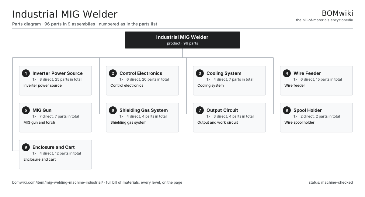
| # | Part | Qty | What it does |
|---|---|---|---|
| 1 | Inverter Power Source 8 parts | 1× | Inverter power source |
| 2 | Control Electronics 6 parts | 1× | Control electronics |
| 3 | Cooling System 4 parts | 1× | Cooling system |
| 4 | Wire Feeder 6 parts | 1× | Wire feeder |
| 5 | MIG Gun 7 parts | 1× | MIG gun and torch |
| 6 | Shielding Gas System 4 parts | 1× | Shielding gas system |
| 7 | Output Circuit 3 parts | 1× | Output and work circuit |
| 8 | Spool Holder 2 parts | 1× | Wire spool holder |
| 9 | Enclosure and Cart 4 parts | 1× | Enclosure and cart |
3D model
No 3D model yet. Have a CAD file of this? Add a 3D model — STL renders right on this page; STEP, FreeCAD, and OpenSCAD sources are welcome too (openly licensed, like all 3D models on BOMwiki).
Build & assembly graph
expand / collapse · shared sub-assemblies converge · links to related products · est. labourTap an assembly to expand/collapse · tap a part to open it · use “Open page” for any node · drag to pan, scroll to zoom.
Bill of materials for Industrial MIG Welder
9 top-level lines · 100 rows shown · 96 parts total · indented to 3 levels| # | Item / sub-assembly | Part no. | Qty/assy | Ext. qty | Parts | Type |
|---|---|---|---|---|---|---|
| 1 | Inverter Power Source 8 parts | mig-welding-machine-industrial-power-source | 1× | 1 | 25 | assembly |
| 1.1 | EMC Filter 3 parts | mig-welding-machine-industrial-emc-filter | 1× | 1 | 5 | assembly |
| 1.1.1 | Common-Mode Choke | mig-welding-machine-industrial-common-mode-choke | 1× | 1 | · | part |
| 1.1.2 | X Capacitor | mig-welding-machine-industrial-x-cap | 2× | 2 | · | part |
| 1.1.3 | Y Capacitor | mig-welding-machine-industrial-y-cap | 2× | 2 | · | part |
| 1.2 | Primary Rectifier Bridge 3 parts | mig-welding-machine-industrial-primary-rectifier | 1× | 1 | 3 | assembly |
| 1.2.1 | Bridge Module | mig-welding-machine-industrial-bridge-module | 1× | 1 | · | part |
| 1.2.2 | Inrush Resistor | mig-welding-machine-industrial-inrush-resistor | 1× | 1 | · | part |
| 1.2.3 | Inrush Relay | mig-welding-machine-industrial-inrush-relay | 1× | 1 | · | part |
| 1.3 | DC Bus Capacitor Bank 3 parts | mig-welding-machine-industrial-bus-cap-bank | 1× | 1 | 7 | assembly |
| 1.3.1 | Bus Capacitor | mig-welding-machine-industrial-electrolytic-cap | 4× | 4 | · | part |
| 1.3.2 | Bleed Resistor | mig-welding-machine-industrial-bleed-resistor | 2× | 2 | · | part |
| 1.3.3 | Capacitor Busbar | mig-welding-machine-industrial-cap-busbar | 1× | 1 | · | part |
| 1.4 | IGBT Module | mig-welding-machine-industrial-igbt-module | 1× | 1 | · | part |
| 1.5 | Power Heatsink | mig-welding-machine-industrial-power-heatsink | 1× | 1 | · | part |
| 1.6 | Main Transformer 4 parts | mig-welding-machine-industrial-main-transformer | 1× | 1 | 4 | assembly |
| 1.6.1 | Ferrite Core | mig-welding-machine-industrial-ferrite-core | 1× | 1 | · | part |
| 1.6.2 | Primary Winding | mig-welding-machine-industrial-primary-winding | 1× | 1 | · | part |
| 1.6.3 | Secondary Winding | mig-welding-machine-industrial-secondary-winding | 1× | 1 | · | part |
| 1.6.4 | Winding Bobbin | mig-welding-machine-industrial-bobbin | 1× | 1 | · | part |
| 1.7 | Output Rectifier 2 parts | mig-welding-machine-industrial-output-rectifier | 1× | 1 | 3 | assembly |
| 1.7.1 | Output Diode | mig-welding-machine-industrial-output-diode | 2× | 2 | · | part |
| 1.7.2 | Snubber Network | mig-welding-machine-industrial-snubber | 1× | 1 | · | part |
| 1.8 | Output Inductor | mig-welding-machine-industrial-output-inductor | 1× | 1 | · | part |
| 2 | Control Electronics 6 parts | mig-welding-machine-industrial-control | 1× | 1 | 20 | assembly |
| 2.1 | Control Board 4 parts | mig-welding-machine-industrial-control-pcb | 1× | 1 | 7 | assembly |
| 2.1.1 | Bare PCB | pcb-bare | 1× | 1 | · | part |
| 2.1.2 | Microcontroller | mcu | 1× | 1 | · | part |
| 2.1.3 | SMD Passive (R/C/L) | smd-passives | 1× | 1 | · | part |
| 2.1.4 | Connector | connector | 4× | 4 | · | part |
| 2.2 | Gate Driver Board 4 parts | mig-welding-machine-industrial-gate-driver | 1× | 1 | 5 | assembly |
| 2.2.1 | Bare PCB | pcb-bare | 1× | 1 | · | part |
| 2.2.2 | Gate Driver IC | mig-welding-machine-industrial-gate-driver-ic | 2× | 2 | · | part |
| 2.2.3 | Desat Network | mig-welding-machine-industrial-desat-network | 1× | 1 | · | part |
| 2.2.4 | SMD Passive (R/C/L) | smd-passives | 1× | 1 | · | part |
| 2.3 | Hall Current Sensor | mig-welding-machine-industrial-current-sensor | 1× | 1 | · | part |
| 2.4 | User Interface Board 4 parts | mig-welding-machine-industrial-ui-board | 1× | 1 | 5 | assembly |
| 2.4.1 | Bare PCB | pcb-bare | 1× | 1 | · | part |
| 2.4.2 | LCD Panel | lcd-panel | 1× | 1 | · | part |
| 2.4.3 | Rotary Encoder | mig-welding-machine-industrial-encoder | 2× | 2 | · | part |
| 2.4.4 | SMD Passive (R/C/L) | smd-passives | 1× | 1 | · | part |
| 2.5 | Communication Port | mig-welding-machine-industrial-comm-port | 1× | 1 | · | part |
| 2.6 | Power Supply | power-supply | 1× | 1 | · | part |
| 3 | Cooling System 4 parts | mig-welding-machine-industrial-cooling | 1× | 1 | 7 | assembly |
| 3.1 | Cooling Fan | mig-welding-machine-industrial-cooling-fan | 1× | 1 | · | part |
| 3.2 | Air Duct | mig-welding-machine-industrial-air-duct | 1× | 1 | · | part |
| 3.3 | Thermal Cutout | mig-welding-machine-industrial-thermostat | 1× | 1 | · | part |
| 3.4 | Water Cooler Unit 4 parts | mig-welding-machine-industrial-water-cooler | 1× | 1 | 4 | assembly |
| 3.4.1 | Coolant Pump | mig-welding-machine-industrial-coolant-pump | 1× | 1 | · | part |
| 3.4.2 | Radiator | mig-welding-machine-industrial-radiator | 1× | 1 | · | part |
| 3.4.3 | Coolant Reservoir | mig-welding-machine-industrial-reservoir | 1× | 1 | · | part |
| 3.4.4 | Flow Switch | mig-welding-machine-industrial-flow-switch | 1× | 1 | · | part |
| 4 | Wire Feeder 6 parts | mig-welding-machine-industrial-wire-feeder | 1× | 1 | 15 | assembly |
| 4.1 | Feed Motor 3 parts | mig-welding-machine-industrial-feed-motor | 1× | 1 | 3 | assembly |
| 4.1.1 | Feed Motor Armature | mig-welding-machine-industrial-feed-motor-armature | 1× | 1 | · | part |
| 4.1.2 | Helical Gear Pair | gear-pair | 1× | 1 | · | part |
| 4.1.3 | Tachometer | mig-welding-machine-industrial-tacho | 1× | 1 | · | part |
| 4.2 | Drive Roll Set 2 parts | mig-welding-machine-industrial-drive-roll-set | 1× | 1 | 4 | assembly |
| 4.2.1 | Drive Roll | mig-welding-machine-industrial-drive-roll | 2× | 2 | · | part |
| 4.2.2 | Roll Key | mig-welding-machine-industrial-roll-key | 2× | 2 | · | part |
| 4.3 | Pressure Arm 3 parts | mig-welding-machine-industrial-pressure-arm | 1× | 1 | 3 | assembly |
| 4.3.1 | Idler Roll | mig-welding-machine-industrial-idler-roll | 1× | 1 | · | part |
| 4.3.2 | Tension Knob | mig-welding-machine-industrial-tension-knob | 1× | 1 | · | part |
| 4.3.3 | Coil Spring | coil-spring | 1× | 1 | · | part |
| 4.4 | Wire Inlet Guide | mig-welding-machine-industrial-wire-inlet-guide | 1× | 1 | · | part |
| 4.5 | Euro Connector | mig-welding-machine-industrial-euro-connector | 1× | 1 | · | part |
| 4.6 | Feeder Board 3 parts | mig-welding-machine-industrial-feeder-pcb | 1× | 1 | 3 | assembly |
| 4.6.1 | Bare PCB | pcb-bare | 1× | 1 | · | part |
| 4.6.2 | Microcontroller | mcu | 1× | 1 | · | part |
| 4.6.3 | SMD Passive (R/C/L) | smd-passives | 1× | 1 | · | part |
| 5 | MIG Gun 7 parts | mig-welding-machine-industrial-torch | 1× | 1 | 7 | assembly |
| 5.1 | Gun Body | mig-welding-machine-industrial-gun-body | 1× | 1 | · | part |
| 5.2 | Trigger Switch | mig-welding-machine-industrial-trigger | 1× | 1 | · | part |
| 5.3 | Swan Neck | mig-welding-machine-industrial-swan-neck | 1× | 1 | · | part |
| 5.4 | Wire Liner | mig-welding-machine-industrial-liner | 1× | 1 | · | part |
| 5.5 | Gas Diffuser | mig-welding-machine-industrial-gas-diffuser | 1× | 1 | · | part |
| 5.6 | Contact Tip | mig-welding-machine-industrial-contact-tip | 1× | 1 | · | part |
| 5.7 | Gas Nozzle | mig-welding-machine-industrial-nozzle | 1× | 1 | · | part |
| 6 | Shielding Gas System 4 parts | mig-welding-machine-industrial-gas-system | 1× | 1 | 4 | assembly |
| 6.1 | Gas Inlet | mig-welding-machine-industrial-gas-inlet | 1× | 1 | · | part |
| 6.2 | Gas Solenoid | mig-welding-machine-industrial-gas-solenoid | 1× | 1 | · | part |
| 6.3 | Flowmeter Mount | mig-welding-machine-industrial-flowmeter-mount | 1× | 1 | · | part |
| 6.4 | Gas Hose | mig-welding-machine-industrial-gas-hose | 1× | 1 | · | part |
| 7 | Output Circuit 3 parts | mig-welding-machine-industrial-output-circuit | 1× | 1 | 4 | assembly |
| 7.1 | Dinse Terminal | mig-welding-machine-industrial-dinse-terminal | 1× | 1 | · | part |
| 7.2 | Polarity Busbar | mig-welding-machine-industrial-polarity-busbar | 1× | 1 | · | part |
| 7.3 | Work Clamp 2 parts | mig-welding-machine-industrial-work-clamp | 1× | 1 | 2 | assembly |
| 7.3.1 | Clamp Jaw | mig-welding-machine-industrial-clamp-jaw | 1× | 1 | · | part |
| 7.3.2 | Work Cable | mig-welding-machine-industrial-work-cable | 1× | 1 | · | part |
| 8 | Spool Holder 2 parts | mig-welding-machine-industrial-spool | 1× | 1 | 2 | assembly |
| 8.1 | Spool Hub | mig-welding-machine-industrial-spool-hub | 1× | 1 | · | part |
| 8.2 | Spool Brake | mig-welding-machine-industrial-spool-brake | 1× | 1 | · | part |
| 9 | Enclosure and Cart 4 parts | mig-welding-machine-industrial-enclosure | 1× | 1 | 12 | assembly |
| 9.1 | Sheet Metal Panel | sheet-panel | 4× | 4 | · | part |
| 9.2 | Front Panel | mig-welding-machine-industrial-front-panel | 1× | 1 | · | part |
| 9.3 | Lift Handle | mig-welding-machine-industrial-handle | 1× | 1 | · | part |
| 9.4 | Cart 3 parts | mig-welding-machine-industrial-cart | 1× | 1 | 6 | assembly |
| 9.4.1 | Cart Frame | mig-welding-machine-industrial-cart-frame | 1× | 1 | · | part |
| 9.4.2 | Cart Wheel | mig-welding-machine-industrial-cart-wheel | 4× | 4 | · | part |
| 9.4.3 | Cylinder Strap | mig-welding-machine-industrial-cylinder-strap | 1× | 1 | · | part |
Related products
same domain, ranked by shared parts Compression Spring Coiler
1,167 parts · shares 4 with this page
Compression Spring Coiler
1,167 parts · shares 4 with this page
 Continuous Belt Furnace
130 parts · shares 4 with this page
Continuous Belt Furnace
130 parts · shares 4 with this page
 Crankshaft Grinder
511 parts · shares 4 with this page
Crankshaft Grinder
511 parts · shares 4 with this page
Sourcing: possible vendors
Prices, MOQ, and lead times are algorithmic estimates, not quotes, and not claims about these companies. Company mappings are curated by keyword; est. price band $10k–$1M. How estimates work| Vendor | HQ | Specialty | MOQ | Lead time |
|---|---|---|---|---|
|
🇩🇪DMG MORI
dmgmori.com ↗
|
Bielefeld, DE | Machine tools | 5 units | 12–20 wks |
|
🇯🇵Mazak
mazak.com ↗
|
Oguchi, JP | Machine tools | 5 units | 12–20 wks |
| haascnc.com ↗ | Oxnard, US | CNC machine tools | 5 units | 12–20 wks |
|
🇯🇵Okuma
okuma.com ↗
|
Niwa, JP | Machine tools | 5 units | 12–20 wks |
|
🇩🇪Trumpf
trumpf.com ↗
|
Ditzingen, DE | Laser & sheet-metal machines | 5 units | 12–20 wks |
1,225-word article