Metal Cutting Band Saw
ProductOverview
A metal cutting band saw severs bar, tube, and structural steel with a thin continuous loop of toothed band that runs in one direction past the work. Unlike an abrasive or cold saw that uses a spinning disc, the band saw drags a long flexible blade across the cut, so each tooth takes only a tiny bite and the long contact length spreads wear over hundreds of teeth. This makes it the workhorse of the cutoff room: it cuts a wide range of sections cleanly, with little kerf loss and modest power, though slower than a cold saw on the same bar.
The machine is built around a pivoting Saw Bow that carries two wheels and the Saw Band. The bow swings down under the Down-Feed Control control while the Clamping Vise grips the stock and the Coolant System system floods the cut. The whole assembly sits on the Frame and Base, driven by the Band Drive and run from the Electrical Control.
The band and how it cuts
The Saw Band is a welded loop of bimetal strip. Its body is the flexible Band Backer, a spring-steel ribbon that bends around the wheels without fatiguing, and welded to its edge is the Tooth Edge of high-speed steel that does the cutting. A single Band Weld closes the strip into an endless loop. The teeth use a variable pitch so that at no instant are too many teeth in the cut, which keeps each tooth loaded and suppresses chatter. As the band runs, each tooth shears a chip a few thousandths of a millimetre thick, and because the band is long, the same stretch of teeth only returns to the cut after cooling on its trip around the wheels.
Bow, wheels, and drive
The Saw Bow is a rigid Bow Casting that holds the Drive Wheel and the Idler Wheel in alignment. The drive wheel is rubber tired and pulls the band; the idler wheel carries the tension and is canted slightly to track the band so it does not creep off the wheels. A Chip Brush sweeps chips out of the gullets before the teeth re-enter the cut. Power comes from the Band Drive, where a Drive Motor turns a Worm Gearbox through a Drive Belt. The worm Worm Gearbox drops motor speed to band speed and turns the output 90 degrees, using a Helical Gear Pair in a Gearbox Housing sealed by Oil Seals.
Guides, vise, and squareness
A band is wide and flat but happy to wander, so the Blade Guide Set twists it edge-down in the cut zone and holds it there. Each Guide Arm carries Carbide Guide inserts that grip the band sides and a Back-up Roller that takes the cutting thrust from behind. One arm slides to suit the stock width so the guides sit as close to the work as possible, which is what keeps the cut straight. The Clamping Vise clamps the stock with a fixed Fixed Jaw that references the miter angle and a Moving Jaw driven by a Vise Cylinder, with a Vise Screw for quick manual setting.
Feed, coolant, and control
The Down-Feed Control lowers the bow at a steady rate. A Feed Cylinder supports the bow weight, a Feed Valve meters the descent, and a Counterbalance lets the operator dial in a light feed on thin tube without the bow crashing through. The Coolant System system floods the cut: a Coolant Pump pulls fluid from the Coolant Tank and sprays it through Coolant Nozzles at both guides, while a Chip Tray catches the swarf. The Electrical Control runs the cycle: a Control Panel sets band speed and feed, and a Blade Deviation Sensor sensor stops the saw if the band wanders or snaps.
Variants and use
Horizontal saws like this dominate cutoff work in steel service centers, weld shops, and machine shops. Larger dual-column versions guide the band on two posts for very accurate cuts on big sections, while smaller swing-frame units trade accuracy for low cost. Automatic feeders index bar through the Clamping Vise to cut many identical lengths unattended. Operators pick band pitch and speed by material: coarse slow settings for thick solid steel, fine fast settings for thin-wall tube, with the goal of keeping at least three teeth in the cut at all times.
Blade life and maintenance
Band life is the running cost of the saw, and it depends on a few habits. A new Saw Band must be broken in by running the first cuts at reduced feed so the fresh teeth hone rather than chip, after which the band can take full feed. Tension matters as much as feed: too little and the band wanders and the cut bows, too much and the Band Weld fatigues and the band snaps. The Blade Guide Set is kept close to the work and the Carbide Guide inserts checked for wear, since worn guides let the band twist and cut crooked. The Coolant System must stay clean and at strength so the teeth run cool, and the Chip Brush must actually clear the gullets, because chips carried back into the cut wear the teeth fast. Most band failures trace to one of these: wrong pitch for the section, a worn guide, weak coolant, or feeding faster than the teeth can clear. When all of them are right, a bimetal band cuts a long shift of steel before it dulls, and the variable-pitch teeth give a quiet, straight cut. This balance of low consumable cost, modest power, wide capacity, and a clean enough face is why the horizontal band saw is the default cutoff machine in the great majority of steel shops, with cold saws and friction saws reserved for the jobs where edge quality or raw speed justify their higher cost.
Metal Cutting Band Saw parts and their functions
9 top-level parts · 63 parts in total · full bill of materials below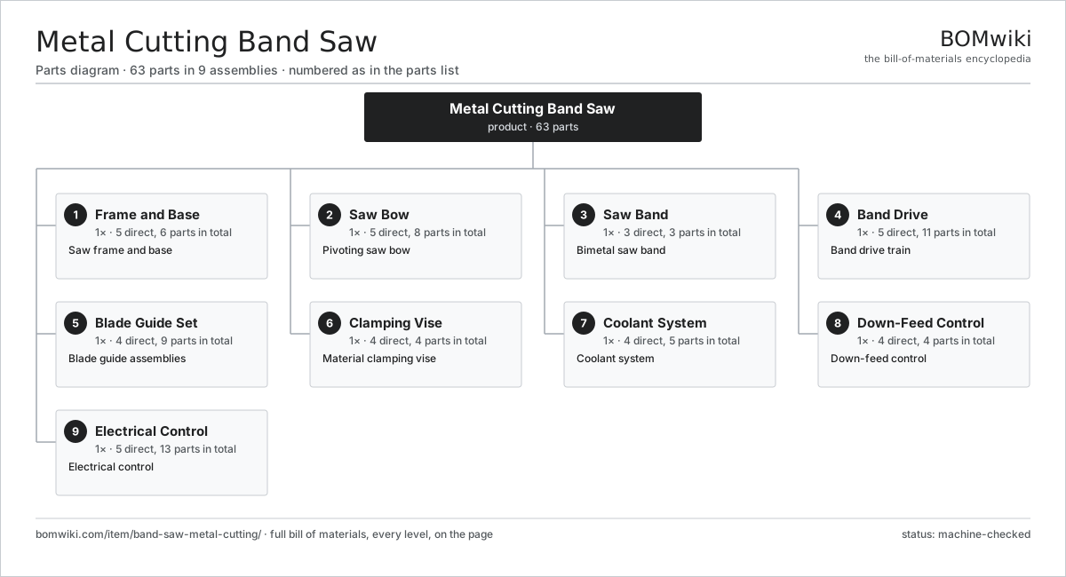
| # | Part | Qty | What it does |
|---|---|---|---|
| 1 | Frame and Base 5 parts | 1× | Saw frame and base |
| 2 | Saw Bow 5 parts | 1× | Pivoting saw bow |
| 3 | Saw Band 3 parts | 1× | Bimetal saw band |
| 4 | Band Drive 5 parts | 1× | Band drive train |
| 5 | Blade Guide Set 4 parts | 1× | Blade guide assemblies |
| 6 | Clamping Vise 4 parts | 1× | Material clamping vise |
| 7 | Coolant System 4 parts | 1× | Coolant system |
| 8 | Down-Feed Control 4 parts | 1× | Down-feed control |
| 9 | Electrical Control 5 parts | 1× | Electrical control |
3D model
No 3D model yet. Have a CAD file of this? Add a 3D model — STL renders right on this page; STEP, FreeCAD, and OpenSCAD sources are welcome too (openly licensed, like all 3D models on BOMwiki).
Build & assembly graph
expand / collapse · shared sub-assemblies converge · links to related products · est. labourTap an assembly to expand/collapse · tap a part to open it · use “Open page” for any node · drag to pan, scroll to zoom.
Bill of materials for Metal Cutting Band Saw
9 top-level lines · 52 rows shown · 63 parts total · indented to 3 levels| # | Item / sub-assembly | Part no. | Qty/assy | Ext. qty | Parts | Type |
|---|---|---|---|---|---|---|
| 1 | Frame and Base 5 parts | band-saw-metal-cutting-frame | 1× | 1 | 6 | assembly |
| 1.1 | Base Weldment | band-saw-metal-cutting-base-weldment | 1× | 1 | · | part |
| 1.2 | Pivot Bracket | band-saw-metal-cutting-pivot-bracket | 1× | 1 | · | part |
| 1.3 | Work Table | band-saw-metal-cutting-work-table | 1× | 1 | · | part |
| 1.4 | Roller Support | band-saw-metal-cutting-roller-support | 2× | 2 | · | part |
| 1.5 | Fastener Set | fastener-set | 1× | 1 | · | part |
| 2 | Saw Bow 5 parts | band-saw-metal-cutting-bow | 1× | 1 | 8 | assembly |
| 2.1 | Bow Casting | band-saw-metal-cutting-bow-casting | 1× | 1 | · | part |
| 2.2 | Drive Wheel | band-saw-metal-cutting-drive-wheel | 1× | 1 | · | part |
| 2.3 | Idler Wheel | band-saw-metal-cutting-idler-wheel | 1× | 1 | · | part |
| 2.4 | Chip Brush | band-saw-metal-cutting-wheel-brush | 1× | 1 | · | part |
| 2.5 | Ball Bearing | ball-bearing | 4× | 4 | · | part |
| 3 | Saw Band 3 parts | band-saw-metal-cutting-blade | 1× | 1 | 3 | assembly |
| 3.1 | Band Backer | band-saw-metal-cutting-band-backer | 1× | 1 | · | part |
| 3.2 | Tooth Edge | band-saw-metal-cutting-tooth-edge | 1× | 1 | · | part |
| 3.3 | Band Weld | band-saw-metal-cutting-weld-joint | 1× | 1 | · | part |
| 4 | Band Drive 5 parts | band-saw-metal-cutting-drive | 1× | 1 | 11 | assembly |
| 4.1 | Drive Motor | band-saw-metal-cutting-drive-motor | 1× | 1 | · | part |
| 4.2 | Worm Gearbox 4 parts | band-saw-metal-cutting-gearbox | 1× | 1 | 5 | assembly |
| 4.2.1 | Helical Gear Pair | gear-pair | 1× | 1 | · | part |
| 4.2.2 | Gearbox Housing | gearbox-housing | 1× | 1 | · | part |
| 4.2.3 | Ball Bearing | ball-bearing | 2× | 2 | · | part |
| 4.2.4 | Oil Seal | oil-seal | 1× | 1 | · | part |
| 4.3 | Drive Belt | drive-belt | 1× | 1 | · | part |
| 4.4 | Oil Seal | oil-seal | 2× | 2 | · | part |
| 4.5 | Ball Bearing | ball-bearing | 2× | 2 | · | part |
| 5 | Blade Guide Set 4 parts | band-saw-metal-cutting-guide-set | 1× | 1 | 9 | assembly |
| 5.1 | Guide Arm | band-saw-metal-cutting-guide-arm | 2× | 2 | · | part |
| 5.2 | Carbide Guide | band-saw-metal-cutting-carbide-guide | 4× | 4 | · | part |
| 5.3 | Back-up Roller | band-saw-metal-cutting-backup-roller | 2× | 2 | · | part |
| 5.4 | Fastener Set | fastener-set | 1× | 1 | · | part |
| 6 | Clamping Vise 4 parts | band-saw-metal-cutting-vise | 1× | 1 | 4 | assembly |
| 6.1 | Fixed Jaw | band-saw-metal-cutting-fixed-jaw | 1× | 1 | · | part |
| 6.2 | Moving Jaw | band-saw-metal-cutting-moving-jaw | 1× | 1 | · | part |
| 6.3 | Vise Cylinder | band-saw-metal-cutting-vise-cylinder | 1× | 1 | · | part |
| 6.4 | Vise Screw | band-saw-metal-cutting-vise-screw | 1× | 1 | · | part |
| 7 | Coolant System 4 parts | band-saw-metal-cutting-coolant | 1× | 1 | 5 | assembly |
| 7.1 | Coolant Pump | band-saw-metal-cutting-coolant-pump | 1× | 1 | · | part |
| 7.2 | Coolant Tank | band-saw-metal-cutting-coolant-tank | 1× | 1 | · | part |
| 7.3 | Coolant Nozzle | band-saw-metal-cutting-coolant-nozzle | 2× | 2 | · | part |
| 7.4 | Chip Tray | band-saw-metal-cutting-chip-tray | 1× | 1 | · | part |
| 8 | Down-Feed Control 4 parts | band-saw-metal-cutting-feed | 1× | 1 | 4 | assembly |
| 8.1 | Feed Cylinder | band-saw-metal-cutting-feed-cylinder | 1× | 1 | · | part |
| 8.2 | Feed Valve | band-saw-metal-cutting-feed-valve | 1× | 1 | · | part |
| 8.3 | Counterbalance | band-saw-metal-cutting-counterbalance | 1× | 1 | · | part |
| 8.4 | Pressure Sensor | pressure-sensor | 1× | 1 | · | part |
| 9 | Electrical Control 5 parts | band-saw-metal-cutting-control | 1× | 1 | 13 | assembly |
| 9.1 | Control Panel | band-saw-metal-cutting-control-panel | 1× | 1 | · | part |
| 9.2 | Blade Deviation Sensor | band-saw-metal-cutting-blade-deviation | 1× | 1 | · | part |
| 9.3 | Relay | relay | 4× | 4 | · | part |
| 9.4 | Connector | connector | 6× | 6 | · | part |
| 9.5 | Wire Bundle | wire-bundle | 1× | 1 | · | part |
Related products
same domain, ranked by shared parts Bevel Gear Generator
201 parts · shares 3 with this page
Blanking Press Line
350 parts · shares 3 with this page
Cold Rolling Mill
991 parts · shares 3 with this page
Bevel Gear Generator
201 parts · shares 3 with this page
Blanking Press Line
350 parts · shares 3 with this page
Cold Rolling Mill
991 parts · shares 3 with this page
 Creep-Feed Grinder
571 parts · shares 3 with this page
Double-Disc Grinder
153 parts · shares 3 with this page
Drag Finishing Machine
735 parts · shares 3 with this page
Creep-Feed Grinder
571 parts · shares 3 with this page
Double-Disc Grinder
153 parts · shares 3 with this page
Drag Finishing Machine
735 parts · shares 3 with this page
Sourcing: possible vendors
Prices, MOQ, and lead times are algorithmic estimates, not quotes, and not claims about these companies. Company mappings are curated by keyword; est. price band $10k–$1M. How estimates work| Vendor | HQ | Specialty | MOQ | Lead time |
|---|---|---|---|---|
|
🇩🇪DMG MORI
dmgmori.com ↗
|
Bielefeld, DE | Machine tools | 5 units | 12–20 wks |
|
🇯🇵Mazak
mazak.com ↗
|
Oguchi, JP | Machine tools | 5 units | 12–20 wks |
| haascnc.com ↗ | Oxnard, US | CNC machine tools | 5 units | 12–20 wks |
|
🇯🇵Okuma
okuma.com ↗
|
Niwa, JP | Machine tools | 5 units | 12–20 wks |
|
🇩🇪Trumpf
trumpf.com ↗
|
Ditzingen, DE | Laser & sheet-metal machines | 5 units | 12–20 wks |
1,148-word article