Bevel Gear Generator
ProductOverview
A bevel gear generator cuts the teeth of gears whose axes meet at an angle, the gears that turn a drive through a corner. Unlike spur and helical gears, bevel gear teeth lie on a cone, taper along their length, and on spiral and hypoid types curve across the face. No single forming cutter can produce that geometry directly, so the machine builds each flank by generating: it rolls a cutter against the blank while the blank rotates in a fixed ratio, and the envelope of the cutter's many passes becomes the finished tooth surface. The Cutter Head System does the cutting, the Generating Cradle supplies the generating roll, and the Work Spindle and Column presents and turns the blank. Machines of this class produce differential ring-and-pinion sets, industrial bevel boxes, and aerospace transmission gears at modules from roughly 0.5 to 25 mm and diameters up to about a metre.
The generating principle
The idea behind every bevel generator is an imaginary crown gear, a bevel gear with a 90-degree pitch cone that meshes with the gear being cut. The cradle physically represents one tooth of that crown gear. As the Cradle Roll Drive rolls the cradle through its generating arc, the cutter blades trace where a crown-gear tooth would sweep, and the work spindle rotates in exact ratio so the blank rolls against that virtual tooth. The flank that results is conjugate to the crown gear, which makes the finished gear conjugate to its mate. On mechanical machines the ratio is fixed by the Generating Roll Cam and a stack of Change Gears; on CNC machines an electronic gearing law in the CNC Control enforces it, which is why modern generators are described as six-axis machines: cutter, cradle, work rotation, and three linear settings all move under one timed motion. After each tooth is generated, the Indexing and Roll Drive drive steps the blank one pitch and the cycle repeats.
Cutter head and blades
For spiral bevel and hypoid work the cutter is a face mill: a Face Mill Cutter Body body 88 to 500 mm in diameter carrying alternating inside and outside Stick Blades locked by Blade Clamps. The blades are bar-form tools ground with the required pressure angle and re-sharpened on the front face many times. Blade material is high-speed steel for general work and coated carbide where cutting speed and tool life matter, with titanium-nitride and aluminium-titanium-nitride coatings common on production blades. The Cutter Spindle runs the head at 50 to 600 rpm and its runout prints onto every flank, so it is built stiff and bearing-controlled. Straight bevel gears are cut differently: a Straight-Bevel Tool Set pair of reciprocating planing tools shaves each flank as the cradle rolls, one tool per side, which is why straight-bevel generators are sometimes called two-tool generators.
Workholding and setup
Bevel gear accuracy is unforgiving of blank location. The Locating Arbor seats the blank bore concentric to the work spindle, the Locating Backplate sets the axial mounting distance, and the Hydraulic Clamp Nut draws everything together with repeatable force; an Expanding Collet is used where a bored hub is gripped from inside. Setup of the machine itself is the real craft. The Root-Angle Swivel sets the work to the gear root angle, the Eccentric Cutter Mount sets cutter radial position and tilt, and the mounting distance positions the blank cone against the cutter. These settings shape the tooth contact pattern, the patch of actual contact between gear and pinion under load. Cut a test set, roll it on a tester, read the pattern, and correct the machine settings: the loop runs until the pattern sits where the design wants it. CNC machines fold these corrections into the motion law rather than into physical shims.
Materials, variants, and accuracy
Blanks are usually case-hardening steels such as 20MnCr5 or 8620, cut soft and then carburized and hardened, after which the flanks are finished by lapping or by hard cutting and grinding on a separate machine. Cutting is done with neat oil from the Coolant and Lubrication system rather than water-based fluid, because the interrupted bevel cut and the stick-blade geometry favour oil's lubricity, and the Chip Conveyor clears the hot chips it produces. Variants follow the gear types: straight bevel for low-speed and hand-operated drives, spiral bevel for smooth high-speed meshing, zerol bevel as a curved-tooth gear with zero spiral angle, and hypoid for offset axes as in a rear axle. The two historic system families, the face-milling approach associated with Gleason and the face-hobbing approach associated with Klingelnberg and Oerlikon, differ in whether the blank indexes between teeth or rolls continuously with the cutter.
Use and production context
Most bevel gears in service were cut on machines of this kind, from the ring-and-pinion in a car axle to the angle drives in helicopters and ship gearboxes. Production runs justify the long setup: once the Change Gears or CNC program and the contact pattern are dialed in, the machine repeats parts to DIN or AGMA accuracy classes in the 5 to 7 range, climbing higher when the gears are subsequently ground. The Machine Bed and Frame supplies the mass and damping that interrupted cutting demands, and the CNC Control Cabinet coordinate the generating roll, indexing, and feed so that the operator manages gear data and corrections rather than the underlying kinematics.
Bevel Gear Generator parts and their functions
8 top-level parts · 201 parts in total · full bill of materials below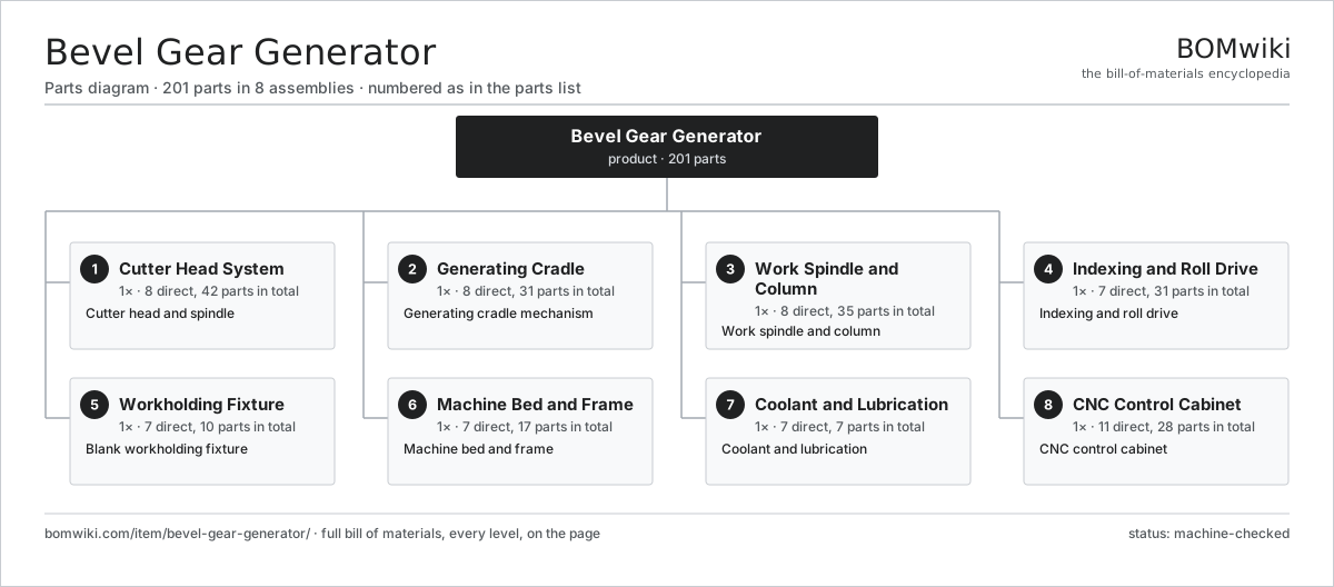
| # | Part | Qty | What it does |
|---|---|---|---|
| 1 | Cutter Head System 8 parts | 1× | Cutter head and spindle |
| 2 | Generating Cradle 8 parts | 1× | Generating cradle mechanism |
| 3 | Work Spindle and Column 8 parts | 1× | Work spindle and column |
| 4 | Indexing and Roll Drive 7 parts | 1× | Indexing and roll drive |
| 5 | Workholding Fixture 7 parts | 1× | Blank workholding fixture |
| 6 | Machine Bed and Frame 7 parts | 1× | Machine bed and frame |
| 7 | Coolant and Lubrication 7 parts | 1× | Coolant and lubrication |
| 8 | CNC Control Cabinet 11 parts | 1× | CNC control cabinet |
3D model
No 3D model yet. Have a CAD file of this? Add a 3D model — STL renders right on this page; STEP, FreeCAD, and OpenSCAD sources are welcome too (openly licensed, like all 3D models on BOMwiki).
Build & assembly graph
expand / collapse · shared sub-assemblies converge · links to related products · est. labourTap an assembly to expand/collapse · tap a part to open it · use “Open page” for any node · drag to pan, scroll to zoom.
Bill of materials for Bevel Gear Generator
8 top-level lines · 83 rows shown · 201 parts total · indented to 3 levels| # | Item / sub-assembly | Part no. | Qty/assy | Ext. qty | Parts | Type |
|---|---|---|---|---|---|---|
| 1 | Cutter Head System 8 parts | bevel-gear-generator-cutter-head | 1× | 1 | 42 | assembly |
| 1.1 | Face Mill Cutter Body | bevel-gear-generator-face-cutter | 1× | 1 | · | part |
| 1.2 | Stick Blades | bevel-gear-generator-stick-blades | 16× | 16 | · | part |
| 1.3 | Blade Clamps | bevel-gear-generator-blade-clamps | 16× | 16 | · | part |
| 1.4 | Cutter Spindle | bevel-gear-generator-cutter-spindle | 1× | 1 | · | part |
| 1.5 | Cutter Drive Motor | bevel-gear-generator-cutter-motor | 1× | 1 | · | part |
| 1.6 | Straight-Bevel Tool Set | bevel-gear-generator-straight-tools | 2× | 2 | · | part |
| 1.7 | Ball Bearing | ball-bearing | 4× | 4 | · | part |
| 1.8 | Drive Belt | drive-belt | 1× | 1 | · | part |
| 2 | Generating Cradle 8 parts | bevel-gear-generator-cradle | 1× | 1 | 31 | assembly |
| 2.1 | Cradle Ring | bevel-gear-generator-cradle-ring | 1× | 1 | · | part |
| 2.2 | Cradle Slewing Bearing | bevel-gear-generator-cradle-bearing | 1× | 1 | · | part |
| 2.3 | Eccentric Cutter Mount | bevel-gear-generator-eccentric | 1× | 1 | · | part |
| 2.4 | Cradle Roll Drive | bevel-gear-generator-cradle-drive | 1× | 1 | · | part |
| 2.5 | Generating Roll Cam | bevel-gear-generator-roll-cam | 1× | 1 | · | part |
| 2.6 | Servo Motor 4 parts | servo-motor | 1× | 1 | 24 | assembly |
| 2.6.1 | Stator Assembly 3 parts + deeper › | stator-assembly | 1× | 1 | 3 | assembly |
| 2.6.2 | Rotor Assembly 4 parts + deeper › | rotor-assembly | 1× | 1 | 19 | assembly |
| 2.6.3 | Encoder | encoder | 1× | 1 | · | part |
| 2.6.4 | Motor Housing | motor-housing | 1× | 1 | · | part |
| 2.7 | Encoder | encoder | 1× | 1 | · | part |
| 2.8 | Helical Gear Pair | gear-pair | 1× | 1 | · | part |
| 3 | Work Spindle and Column 8 parts | bevel-gear-generator-work-spindle | 1× | 1 | 35 | assembly |
| 3.1 | Work Spindle | bevel-gear-generator-ws-spindle | 1× | 1 | · | part |
| 3.2 | Work Column | bevel-gear-generator-ws-column | 1× | 1 | · | part |
| 3.3 | Root-Angle Swivel | bevel-gear-generator-ws-swivel | 1× | 1 | · | part |
| 3.4 | Work Spindle Drive | bevel-gear-generator-ws-drive | 1× | 1 | · | part |
| 3.5 | Ball Bearing | ball-bearing | 4× | 4 | · | part |
| 3.6 | Servo Motor 4 parts | servo-motor | 1× | 1 | 24 | assembly |
| 3.6.1 | Stator Assembly 3 parts + deeper › | stator-assembly | 1× | 1 | 3 | assembly |
| 3.6.2 | Rotor Assembly 4 parts + deeper › | rotor-assembly | 1× | 1 | 19 | assembly |
| 3.6.3 | Encoder | encoder | 1× | 1 | · | part |
| 3.6.4 | Motor Housing | motor-housing | 1× | 1 | · | part |
| 3.7 | Encoder | encoder | 1× | 1 | · | part |
| 3.8 | Oil Seal | oil-seal | 2× | 2 | · | part |
| 4 | Indexing and Roll Drive 7 parts | bevel-gear-generator-indexing | 1× | 1 | 31 | assembly |
| 4.1 | Index Worm and Wheel | bevel-gear-generator-index-worm | 1× | 1 | · | part |
| 4.2 | Change Gears | bevel-gear-generator-change-gears | 1× | 1 | · | part |
| 4.3 | Index Clutch | bevel-gear-generator-index-clutch | 1× | 1 | · | part |
| 4.4 | Feed and Depth Cam | bevel-gear-generator-feed-cam | 1× | 1 | · | part |
| 4.5 | Helical Gear Pair | gear-pair | 2× | 2 | · | part |
| 4.6 | Servo Motor 4 parts | servo-motor | 1× | 1 | 24 | assembly |
| 4.6.1 | Stator Assembly 3 parts + deeper › | stator-assembly | 1× | 1 | 3 | assembly |
| 4.6.2 | Rotor Assembly 4 parts + deeper › | rotor-assembly | 1× | 1 | 19 | assembly |
| 4.6.3 | Encoder | encoder | 1× | 1 | · | part |
| 4.6.4 | Motor Housing | motor-housing | 1× | 1 | · | part |
| 4.7 | Encoder | encoder | 1× | 1 | · | part |
| 5 | Workholding Fixture 7 parts | bevel-gear-generator-workholding | 1× | 1 | 10 | assembly |
| 5.1 | Locating Arbor | bevel-gear-generator-arbor | 1× | 1 | · | part |
| 5.2 | Hydraulic Clamp Nut | bevel-gear-generator-clamp-nut | 1× | 1 | · | part |
| 5.3 | Expanding Collet | bevel-gear-generator-collet | 1× | 1 | · | part |
| 5.4 | Locating Backplate | bevel-gear-generator-backplate | 1× | 1 | · | part |
| 5.5 | Coil Spring | coil-spring | 4× | 4 | · | part |
| 5.6 | O-Ring Set | oring-set | 1× | 1 | · | part |
| 5.7 | Fastener Set | fastener-set | 1× | 1 | · | part |
| 6 | Machine Bed and Frame 7 parts | bevel-gear-generator-bed | 1× | 1 | 17 | assembly |
| 6.1 | Bed Casting | bevel-gear-generator-base-casting | 1× | 1 | · | part |
| 6.2 | Slideways | bevel-gear-generator-ways | 1× | 1 | · | part |
| 6.3 | Machine Enclosure | bevel-gear-generator-enclosure | 1× | 1 | · | part |
| 6.4 | Leveling Mount | bevel-gear-generator-leveling | 6× | 6 | · | part |
| 6.5 | Linear Guide Rail | linear-guide | 4× | 4 | · | part |
| 6.6 | Ball Screw | ball-screw | 3× | 3 | · | part |
| 6.7 | Fastener Set | fastener-set | 1× | 1 | · | part |
| 7 | Coolant and Lubrication 7 parts | bevel-gear-generator-coolant | 1× | 1 | 7 | assembly |
| 7.1 | Coolant Pump | coolant-pump | 1× | 1 | · | part |
| 7.2 | Cutting-Oil Tank | bevel-gear-generator-oil-tank | 1× | 1 | · | part |
| 7.3 | Oil Mist Extractor | bevel-gear-generator-mist-extract | 1× | 1 | · | part |
| 7.4 | Chip Conveyor | bevel-gear-generator-chip-conveyor | 1× | 1 | · | part |
| 7.5 | Lubrication Unit | bevel-gear-generator-lube-unit | 1× | 1 | · | part |
| 7.6 | Pressure Sensor | pressure-sensor | 1× | 1 | · | part |
| 7.7 | Gearbox Housing | gearbox-housing | 1× | 1 | · | part |
| 8 | CNC Control Cabinet 11 parts | bevel-gear-generator-controls | 1× | 1 | 28 | assembly |
| 8.1 | CNC Control | bevel-gear-generator-cnc | 1× | 1 | · | part |
| 8.2 | Operator HMI | bevel-gear-generator-hmi | 1× | 1 | · | part |
| 8.3 | Power Supply | power-supply | 1× | 1 | · | part |
| 8.4 | IGBT Power Module | igbt-module | 4× | 4 | · | part |
| 8.5 | Relay | relay | 6× | 6 | · | part |
| 8.6 | Bare PCB | pcb-bare | 2× | 2 | · | part |
| 8.7 | Microcontroller | mcu | 2× | 2 | · | part |
| 8.8 | SMD Passive (R/C/L) | smd-passives | 1× | 1 | · | part |
| 8.9 | Connector | connector | 8× | 8 | · | part |
| 8.10 | Wire Bundle | wire-bundle | 1× | 1 | · | part |
| 8.11 | LCD Panel | lcd-panel | 1× | 1 | · | part |
Related products
same domain, ranked by shared parts Rotary-Table Surface Grinder
172 parts · shares 11 with this page
Spline Rolling Machine
138 parts · shares 10 with this page
Rotary-Table Surface Grinder
172 parts · shares 11 with this page
Spline Rolling Machine
138 parts · shares 10 with this page
 Radial Forging Machine
288 parts · shares 10 with this page
Universal Cylindrical Grinder
153 parts · shares 9 with this page
Double-Disc Grinder
153 parts · shares 9 with this page
Radial Forging Machine
288 parts · shares 10 with this page
Universal Cylindrical Grinder
153 parts · shares 9 with this page
Double-Disc Grinder
153 parts · shares 9 with this page
 Gear Shaping Machine
110 parts · shares 8 with this page
Gear Shaping Machine
110 parts · shares 8 with this page
Sourcing: possible vendors
Prices, MOQ, and lead times are algorithmic estimates, not quotes, and not claims about these companies. Company mappings are curated by keyword; est. price band $10k–$1M. How estimates work| Vendor | HQ | Specialty | MOQ | Lead time |
|---|---|---|---|---|
|
🇩🇪DMG MORI
dmgmori.com ↗
|
Bielefeld, DE | Machine tools | 5 units | 12–20 wks |
|
🇯🇵Mazak
mazak.com ↗
|
Oguchi, JP | Machine tools | 5 units | 12–20 wks |
| haascnc.com ↗ | Oxnard, US | CNC machine tools | 5 units | 12–20 wks |
|
🇯🇵Okuma
okuma.com ↗
|
Niwa, JP | Machine tools | 5 units | 12–20 wks |
|
🇩🇪Trumpf
trumpf.com ↗
|
Ditzingen, DE | Laser & sheet-metal machines | 5 units | 12–20 wks |
964-word article