Gang Drilling Machine
ProductOverview
A gang drilling machine is a row of independent drilling heads mounted side by side over a common table. Each head is set up for a different operation: the first drills a pilot hole, the second opens it to size, the third countersinks or counterbores, and the fourth taps a thread. The operator clamps a part in a fixture, drills under the first head, then slides the part or the table to the next head and repeats. By the time the part has passed under all the heads it is fully machined, and no time is lost changing tools in a single spindle.
The point of a gang drill is changeover-free sequencing. On a plain drill press, drilling, then counterboring, then tapping the same hole means stopping and swapping the tool three times. A gang machine keeps a dedicated tool spinning in each head so the operator only moves the work. This makes it ideal for medium-volume batch work such as flanges, brackets, end plates, and machine-frame components, where the same set of operations is repeated on every part but the run is too small to justify a dedicated transfer line.
Base, column, and beam
The machine is built on a heavy Base & Column. A Base Casting of grey iron carries a Head Beam on one or two Support Column supports, and the heads clamp to a slot in the beam so their spacing can be adjusted to match the part. A T-Slot Bed receives the work table and fixtures. The whole structure is heavy on purpose: drilling, especially with larger bits, produces strong axial thrust and torque, and a rigid base keeps the holes accurate and stops chatter.
Drilling heads
The working tools are the Drilling Head Row, a set of two to eight Drill Head units. Each head has its own Spindle running in a pair of bearings from the shared Ball Bearing leaf, a Quill that slides to feed the tool down, a Drill Chuck or taper to hold the drill, and its own Head Motor. Because each head is independent, the spindle speed of each one is set to suit its tool: a small pilot drill runs fast while a large counterbore runs slow. A Head Slide lets the head be positioned along the beam, and a Depth Stop limits how far the quill travels so every part is drilled to the same depth.
Work table and indexing
The Sliding Work Table slides along Table Ways driven by a Traverse Screw turned through a Traverse Handle. The operator moves the part from head to head by traversing the table, and a set of Index Stop click the table into the right position under each head so alignment is repeatable. On simpler bench machines the operator instead slides the part by hand across a stationary table top, the Table Top, using the fixture to register each station.
Spindle drive and speeds
Each head takes its speed from the Spindle Drive system. The common arrangement is a Step Pulley on the motor and another on the spindle, linked by a Drive Belt using the shared belt leaf, with a Belt Tensioner keeping the belt tight. Moving the belt between grooves selects the speed. Heavier machines add a Helical Gear Pair reduction for low-speed, high-torque tapping. Setting the correct speed for each tool is what makes the gang layout pay off, since the operator never has to compromise one speed across several tool sizes.
Quill feed
Feed is the downward motion of the tool. The Quill Feed Mechanism mechanism on each head is usually a Feed Lever capstan turning a Feed Rack & Pinion rack and pinion, with a Quill Return Spring pulling the quill back up when the lever is released. For deeper holes or production work a Power Feed Unit unit advances the quill automatically at a set rate, which gives a consistent finish and frees the operator to load the next part.
Coolant and chip control
Drilling generates heat at the cutting edge, so the Coolant Supply system pumps cutting fluid from a Coolant Tank sump through a Coolant Pump and a flexible Coolant Nozzle aimed at each drill point. Coolant cools the tool, flushes chips out of the hole, and improves the bore finish, particularly when tapping or reaming.
Control and fixturing
The Electrical Control panel carries a Motor Starter for each head motor, a Pushbutton Station station, and a Power Supply for the control circuit, all wired through the Wire Bundle. Repeatable accuracy comes from the Workholding Fixture: a Jig Plate locates the part on Locating Pin pins, a Work Clamp holds it down, and a Drill Bush guides each drill to the exact hole position. With a good jig the operator can produce hundreds of parts with holes located the same way every time, without measuring or marking out, which is the real productivity gain of the gang drilling machine.
Gang Drilling Machine parts and their functions
8 top-level parts · 124 parts in total · full bill of materials below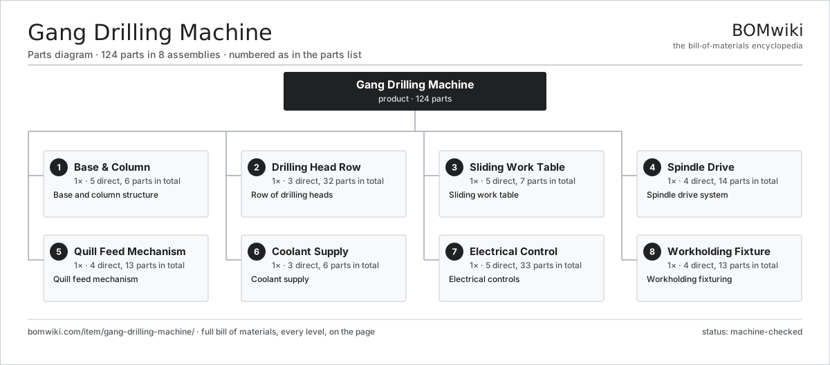
| # | Part | Qty | What it does |
|---|---|---|---|
| 1 | Base & Column 5 parts | 1× | Base and column structure |
| 2 | Drilling Head Row 3 parts | 1× | Row of drilling heads |
| 3 | Sliding Work Table 5 parts | 1× | Sliding work table |
| 4 | Spindle Drive 4 parts | 1× | Spindle drive system |
| 5 | Quill Feed Mechanism 4 parts | 1× | Quill feed mechanism |
| 6 | Coolant Supply 3 parts | 1× | Coolant supply |
| 7 | Electrical Control 5 parts | 1× | Electrical controls |
| 8 | Workholding Fixture 4 parts | 1× | Workholding fixturing |
3D model
No 3D model yet. Have a CAD file of this? Add a 3D model — STL renders right on this page; STEP, FreeCAD, and OpenSCAD sources are welcome too (openly licensed, like all 3D models on BOMwiki).
Build & assembly graph
expand / collapse · shared sub-assemblies converge · links to related products · est. labourTap an assembly to expand/collapse · tap a part to open it · use “Open page” for any node · drag to pan, scroll to zoom.
Bill of materials for Gang Drilling Machine
8 top-level lines · 48 rows shown · 124 parts total · indented to 3 levels| # | Item / sub-assembly | Part no. | Qty/assy | Ext. qty | Parts | Type |
|---|---|---|---|---|---|---|
| 1 | Base & Column 5 parts | gang-drilling-machine-base | 1× | 1 | 6 | assembly |
| 1.1 | Base Casting | gang-drilling-machine-base-casting | 1× | 1 | · | part |
| 1.2 | Head Beam | gang-drilling-machine-beam | 1× | 1 | · | part |
| 1.3 | Support Column | gang-drilling-machine-column | 2× | 2 | · | part |
| 1.4 | T-Slot Bed | gang-drilling-machine-tslot-bed | 1× | 1 | · | part |
| 1.5 | Fastener Set | fastener-set | 1× | 1 | · | part |
| 2 | Drilling Head Row 3 parts | gang-drilling-machine-head-row | 1× | 1 | 32 | assembly |
| 2.1 | Drill Head 5 parts | gang-drilling-machine-head | 4× | 4 | 6 | assembly |
| 2.1.1 | Spindle | gang-drilling-machine-spindle | 1× | 4 | · | part |
| 2.1.2 | Quill | gang-drilling-machine-quill | 1× | 4 | · | part |
| 2.1.3 | Drill Chuck | gang-drilling-machine-chuck | 1× | 4 | · | part |
| 2.1.4 | Head Motor | gang-drilling-machine-head-motor | 1× | 4 | · | part |
| 2.1.5 | Ball Bearing | ball-bearing | 2× | 8 | · | part |
| 2.2 | Head Slide | gang-drilling-machine-head-slide | 4× | 4 | · | part |
| 2.3 | Depth Stop | gang-drilling-machine-depth-stop | 4× | 4 | · | part |
| 3 | Sliding Work Table 5 parts | gang-drilling-machine-table | 1× | 1 | 7 | assembly |
| 3.1 | Table Top | gang-drilling-machine-table-top | 1× | 1 | · | part |
| 3.2 | Table Ways | gang-drilling-machine-table-ways | 2× | 2 | · | part |
| 3.3 | Traverse Screw | gang-drilling-machine-table-screw | 1× | 1 | · | part |
| 3.4 | Traverse Handle | gang-drilling-machine-table-handle | 1× | 1 | · | part |
| 3.5 | Index Stop | gang-drilling-machine-table-stops | 2× | 2 | · | part |
| 4 | Spindle Drive 4 parts | gang-drilling-machine-drive | 1× | 1 | 14 | assembly |
| 4.1 | Step Pulley | gang-drilling-machine-step-pulley | 4× | 4 | · | part |
| 4.2 | Drive Belt | drive-belt | 4× | 4 | · | part |
| 4.3 | Helical Gear Pair | gear-pair | 2× | 2 | · | part |
| 4.4 | Belt Tensioner | gang-drilling-machine-belt-tensioner | 4× | 4 | · | part |
| 5 | Quill Feed Mechanism 4 parts | gang-drilling-machine-feed | 1× | 1 | 13 | assembly |
| 5.1 | Feed Lever | gang-drilling-machine-feed-lever | 4× | 4 | · | part |
| 5.2 | Feed Rack & Pinion | gang-drilling-machine-feed-rack | 4× | 4 | · | part |
| 5.3 | Quill Return Spring | gang-drilling-machine-return-spring | 4× | 4 | · | part |
| 5.4 | Power Feed Unit | gang-drilling-machine-power-feed | 1× | 1 | · | part |
| 6 | Coolant Supply 3 parts | gang-drilling-machine-coolant | 1× | 1 | 6 | assembly |
| 6.1 | Coolant Pump | gang-drilling-machine-coolant-pump | 1× | 1 | · | part |
| 6.2 | Coolant Tank | gang-drilling-machine-coolant-tank | 1× | 1 | · | part |
| 6.3 | Coolant Nozzle | gang-drilling-machine-nozzle | 4× | 4 | · | part |
| 7 | Electrical Control 5 parts | gang-drilling-machine-control | 1× | 1 | 33 | assembly |
| 7.1 | Motor Starter | gang-drilling-machine-starter | 4× | 4 | · | part |
| 7.2 | Relay | relay | 6× | 6 | · | part |
| 7.3 | Pushbutton Station 2 parts | gang-drilling-machine-pushbutton | 1× | 1 | 21 | assembly |
| 7.3.1 | Bare PCB | pcb-bare | 1× | 1 | · | part |
| 7.3.2 | SMD Passive (R/C/L) | smd-passives | 20× | 20 | · | part |
| 7.4 | Wire Bundle | wire-bundle | 1× | 1 | · | part |
| 7.5 | Power Supply | power-supply | 1× | 1 | · | part |
| 8 | Workholding Fixture 4 parts | gang-drilling-machine-fixture | 1× | 1 | 13 | assembly |
| 8.1 | Jig Plate | gang-drilling-machine-jig-plate | 1× | 1 | · | part |
| 8.2 | Work Clamp | gang-drilling-machine-clamp | 4× | 4 | · | part |
| 8.3 | Locating Pin | gang-drilling-machine-locating-pin | 4× | 4 | · | part |
| 8.4 | Drill Bush | gang-drilling-machine-drill-bush | 4× | 4 | · | part |
Related products
same domain, ranked by shared parts Bevel Gear Generator
201 parts · shares 2 with this page
Blanking Press Line
350 parts · shares 2 with this page
Bevel Gear Generator
201 parts · shares 2 with this page
Blanking Press Line
350 parts · shares 2 with this page
 Centerless Grinder
129 parts · shares 2 with this page
Cold Rolling Mill
991 parts · shares 2 with this page
Centerless Grinder
129 parts · shares 2 with this page
Cold Rolling Mill
991 parts · shares 2 with this page
 Crankshaft Grinder
511 parts · shares 2 with this page
Crankshaft Grinder
511 parts · shares 2 with this page
Sourcing: possible vendors
Prices, MOQ, and lead times are algorithmic estimates, not quotes, and not claims about these companies. Company mappings are curated by keyword; est. price band $10k–$1M. How estimates work| Vendor | HQ | Specialty | MOQ | Lead time |
|---|---|---|---|---|
|
🇩🇪DMG MORI
dmgmori.com ↗
|
Bielefeld, DE | Machine tools | 5 units | 12–20 wks |
|
🇯🇵Mazak
mazak.com ↗
|
Oguchi, JP | Machine tools | 5 units | 12–20 wks |
| haascnc.com ↗ | Oxnard, US | CNC machine tools | 5 units | 12–20 wks |
|
🇯🇵Okuma
okuma.com ↗
|
Niwa, JP | Machine tools | 5 units | 12–20 wks |
|
🇩🇪Trumpf
trumpf.com ↗
|
Ditzingen, DE | Laser & sheet-metal machines | 5 units | 12–20 wks |
917-word article