Engine Lathe
ProductOverview
An engine lathe is the basic machine of metal turning: it spins a workpiece against a fixed cutting tool to make round parts. The name is historical, dating from when these lathes were first driven by steam engines, and it now just means a general-purpose horizontal lathe with a geared headstock, a screw-cutting feed, and a tailstock. Almost every cylindrical metal part begins on a lathe like this, and the machine can face, turn, bore, drill, knurl, and cut threads. It is the first machine taught to a machinist because its four motions, spindle rotation plus three slide travels, underlie most of metal cutting.
The machine is built along a long Bed & Ways whose hardened ways carry the Geared Headstock at one end, the Tailstock at the other, and the Carriage & Apron sliding between them. The Feed & Thread Train connects spindle rotation to carriage motion so that feeds and threads are cut in fixed ratio to the turning work.
Bed and ways
The Bed & Ways sets the accuracy of everything else. The Bed Casting is a heavy ribbed box section that damps vibration, and along its top run the Hardened V-Way and Hardened Flat Way, induction-hardened and ground so the carriage and tailstock track straight and parallel to the spindle axis. Any wear or twist in the ways prints directly onto the diameter and straightness of the work, so the bed is leveled carefully on its Bed Leg & Foots and kept clean by Way Wipers.
Headstock and spindle
The Geared Headstock holds and drives the work. The Work Spindle is a hollow hardened shaft running on preloaded Spindle Bearings, bored through so bar stock can pass and nosed to take the 3-Jaw Chuck. An Main Drive Motor drives it through a Speed Gearbox whose Shift Forks select discrete speeds, with a Back Gear available for the very low speeds and high torque that large diameters and threading need. The 3-Jaw Chuck grips the work: its Scroll Plate drives all three Chuck Jaws together so round stock self-centers.
Carriage, cross slide, and tool post
The Carriage & Apron carries the tool along the bed. Its Saddle bridges the ways and carries the Cross Slide, which moves the tool in and out on the Cross-Slide Screw to set diameter. On top sits the Compound Rest, a swiveling rest for short tapers and chamfers, and the Quick-Change Tool Post clamps the cutting tool. Underneath, the Apron holds the controls that engage power feed and threading: the Feed Clutch for plain turning and the Half-Nut, which clamps onto the lead screw to cut threads.
Feeds and thread cutting
The link between spindle and carriage is the Feed & Thread Train. A Quick-Change Gearbox, the Norton gearbox, lets the operator pick a feed rate or thread pitch with a few levers instead of swapping Change Gears by hand. It drives two shafts down the front of the bed: the Feed Rod for ordinary turning feeds and the Lead Screw for threading. To cut a thread, the operator engages the half-nut on the lead screw so the carriage advances one thread pitch per spindle turn, tracing the helix into the work. A Reversing Tumbler reverses the feed direction for left-hand threads and facing.
Tailstock and supporting work
The Tailstock supports the free end of long parts and holds axial tools. Its Tailstock Quill feeds in and out on the Quill Feed Screw, carrying a Dead Center for support or a drill chuck in its Morse taper. The body can be set over to turn shallow tapers between centers, and it clamps anywhere along the bed.
Auxiliaries, materials, and use
A Lubrication System system meters oil to the headstock, apron, and slideways, and a Coolant System system floods the cut to clear chips and cool the edge. The Electrical Control cabinet holds the motor starter and a forward-off-reverse Spindle Direction Lever, and an Chuck & Chip Guards set with an Guard Interlock shields the chuck. Castings are gray iron, ways and spindle are hardened alloy steel, and gears are case-hardened and ground. The lead screw is held to a tight pitch tolerance over its length because any error there transfers straight into the pitch of a cut thread, and the spindle bearings are set with a small preload so the work runs true under cutting load.
The engine lathe suits toolrooms, repair shops, and small production, handling everything from a single shaft to a batch of bushings. Typical jobs include facing and centering bar ends, turning shafts to diameter, boring and reaming holes, cutting internal and external threads, knurling grips, and parting finished pieces off the stock. Common accessories extend its range further: a steady rest and a follower rest support long slender work against tool pressure, a faceplate and dog let irregular parts turn between centers, and a four-jaw chuck grips square or off-center blanks. Because nearly every cylindrical part can be made on it and the four basic motions teach the logic of all turning, the engine lathe remains the reference machine against which other lathes are described.
Engine Lathe parts and their functions
11 top-level parts · 217 parts in total · full bill of materials below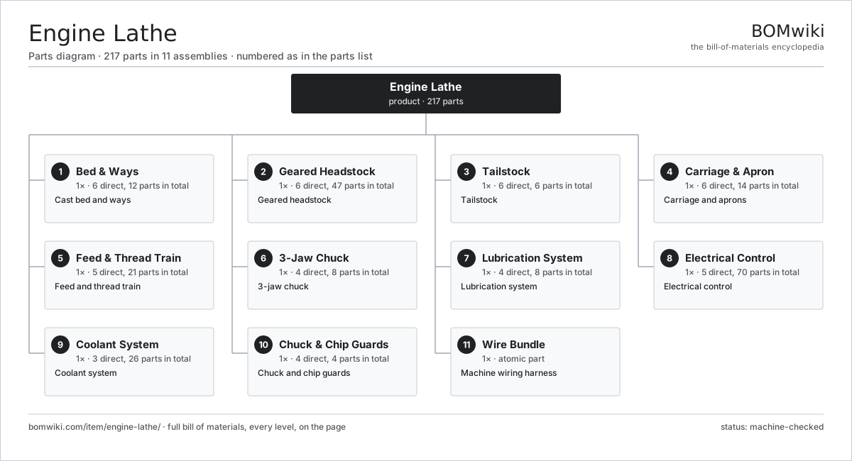
| # | Part | Qty | What it does |
|---|---|---|---|
| 1 | Bed & Ways 6 parts | 1× | Cast bed and ways |
| 2 | Geared Headstock 6 parts | 1× | Geared headstock |
| 3 | Tailstock 6 parts | 1× | Tailstock |
| 4 | Carriage & Apron 6 parts | 1× | Carriage and aprons |
| 5 | Feed & Thread Train 5 parts | 1× | Feed and thread train |
| 6 | 3-Jaw Chuck 4 parts | 1× | 3-jaw chuck |
| 7 | Lubrication System 4 parts | 1× | Lubrication system |
| 8 | Electrical Control 5 parts | 1× | Electrical control |
| 9 | Coolant System 3 parts | 1× | Coolant system |
| 10 | Chuck & Chip Guards 4 parts | 1× | Chuck and chip guards |
| 11 | Wire Bundle | 1× | Machine wiring harness |
3D model
No 3D model yet. Have a CAD file of this? Add a 3D model — STL renders right on this page; STEP, FreeCAD, and OpenSCAD sources are welcome too (openly licensed, like all 3D models on BOMwiki).
Build & assembly graph
expand / collapse · shared sub-assemblies converge · links to related products · est. labourTap an assembly to expand/collapse · tap a part to open it · use “Open page” for any node · drag to pan, scroll to zoom.
Bill of materials for Engine Lathe
11 top-level lines · 91 rows shown · 217 parts total · indented to 3 levels| # | Item / sub-assembly | Part no. | Qty/assy | Ext. qty | Parts | Type |
|---|---|---|---|---|---|---|
| 1 | Bed & Ways 6 parts | engine-lathe-bed | 1× | 1 | 12 | assembly |
| 1.1 | Bed Casting | engine-lathe-bed-casting | 1× | 1 | · | part |
| 1.2 | Hardened V-Way | engine-lathe-v-way | 2× | 2 | · | part |
| 1.3 | Hardened Flat Way | engine-lathe-flat-way | 2× | 2 | · | part |
| 1.4 | Way Wiper | engine-lathe-way-wiper | 4× | 4 | · | part |
| 1.5 | Bed Leg & Foot | engine-lathe-bed-foot | 2× | 2 | · | part |
| 1.6 | Fastener Set | fastener-set | 1× | 1 | · | part |
| 2 | Geared Headstock 6 parts | engine-lathe-headstock | 1× | 1 | 47 | assembly |
| 2.1 | Work Spindle | engine-lathe-spindle | 1× | 1 | · | part |
| 2.2 | Headstock Casting | engine-lathe-headstock-casting | 1× | 1 | · | part |
| 2.3 | Speed Gearbox 4 parts | engine-lathe-speed-gearbox | 1× | 1 | 16 | assembly |
| 2.3.1 | Helical Gear Pair | gear-pair | 6× | 6 | · | part |
| 2.3.2 | Shift Fork | engine-lathe-shift-fork | 3× | 3 | · | part |
| 2.3.3 | Gearbox Housing | gearbox-housing | 1× | 1 | · | part |
| 2.3.4 | Ball Bearing | ball-bearing | 6× | 6 | · | part |
| 2.4 | Main Drive Motor 5 parts | engine-lathe-main-motor | 1× | 1 | 26 | assembly |
| 2.4.1 | Stator Assembly 3 parts + deeper › | stator-assembly | 1× | 1 | 3 | assembly |
| 2.4.2 | Rotor Assembly 4 parts + deeper › | rotor-assembly | 1× | 1 | 19 | assembly |
| 2.4.3 | Copper Winding | copper-winding | 1× | 1 | · | part |
| 2.4.4 | Motor Housing | motor-housing | 1× | 1 | · | part |
| 2.4.5 | Ball Bearing | ball-bearing | 2× | 2 | · | part |
| 2.5 | Spindle Bearing | engine-lathe-spindle-bearing | 2× | 2 | · | part |
| 2.6 | Back Gear | engine-lathe-back-gear | 1× | 1 | · | part |
| 3 | Tailstock 6 parts | engine-lathe-tailstock | 1× | 1 | 6 | assembly |
| 3.1 | Tailstock Body | engine-lathe-tailstock-casting | 1× | 1 | · | part |
| 3.2 | Tailstock Quill | engine-lathe-quill | 1× | 1 | · | part |
| 3.3 | Quill Feed Screw | engine-lathe-quill-screw | 1× | 1 | · | part |
| 3.4 | Quill Handwheel | engine-lathe-quill-handwheel | 1× | 1 | · | part |
| 3.5 | Tailstock Clamp | engine-lathe-tailstock-clamp | 1× | 1 | · | part |
| 3.6 | Dead Center | engine-lathe-dead-center | 1× | 1 | · | part |
| 4 | Carriage & Apron 6 parts | engine-lathe-carriage | 1× | 1 | 14 | assembly |
| 4.1 | Saddle | engine-lathe-saddle | 1× | 1 | · | part |
| 4.2 | Cross Slide 4 parts | engine-lathe-cross-slide | 1× | 1 | 4 | assembly |
| 4.2.1 | Cross-Slide Screw | engine-lathe-cross-screw | 1× | 1 | · | part |
| 4.2.2 | Cross-Slide Nut | engine-lathe-cross-nut | 1× | 1 | · | part |
| 4.2.3 | Cross Handwheel | engine-lathe-cross-handwheel | 1× | 1 | · | part |
| 4.2.4 | Cross-Slide Gib | engine-lathe-cross-gib | 1× | 1 | · | part |
| 4.3 | Compound Rest 3 parts | engine-lathe-compound | 1× | 1 | 3 | assembly |
| 4.3.1 | Compound Swivel Base | engine-lathe-compound-base | 1× | 1 | · | part |
| 4.3.2 | Compound Screw | engine-lathe-compound-screw | 1× | 1 | · | part |
| 4.3.3 | Compound Handwheel | engine-lathe-compound-handwheel | 1× | 1 | · | part |
| 4.4 | Quick-Change Tool Post | engine-lathe-tool-post | 1× | 1 | · | part |
| 4.5 | Apron 4 parts | engine-lathe-apron | 1× | 1 | 4 | assembly |
| 4.5.1 | Apron Gear Train | engine-lathe-apron-gears | 1× | 1 | · | part |
| 4.5.2 | Half-Nut | engine-lathe-half-nut | 1× | 1 | · | part |
| 4.5.3 | Feed Clutch | engine-lathe-feed-clutch | 1× | 1 | · | part |
| 4.5.4 | Apron Casting | engine-lathe-apron-casting | 1× | 1 | · | part |
| 4.6 | Carriage Handwheel | engine-lathe-carriage-handwheel | 1× | 1 | · | part |
| 5 | Feed & Thread Train 5 parts | engine-lathe-feed-train | 1× | 1 | 21 | assembly |
| 5.1 | Quick-Change Gearbox 4 parts | engine-lathe-quick-change-box | 1× | 1 | 14 | assembly |
| 5.1.1 | Helical Gear Pair | gear-pair | 8× | 8 | · | part |
| 5.1.2 | Tumbler Gear | engine-lathe-tumbler-gear | 1× | 1 | · | part |
| 5.1.3 | Gearbox Housing | gearbox-housing | 1× | 1 | · | part |
| 5.1.4 | Ball Bearing | ball-bearing | 4× | 4 | · | part |
| 5.2 | Lead Screw | engine-lathe-lead-screw | 1× | 1 | · | part |
| 5.3 | Feed Rod | engine-lathe-feed-rod | 1× | 1 | · | part |
| 5.4 | Change Gear | engine-lathe-change-gear | 4× | 4 | · | part |
| 5.5 | Reversing Tumbler | engine-lathe-tumbler | 1× | 1 | · | part |
| 6 | 3-Jaw Chuck 4 parts | engine-lathe-chuck | 1× | 1 | 8 | assembly |
| 6.1 | Chuck Body | engine-lathe-chuck-body | 1× | 1 | · | part |
| 6.2 | Scroll Plate | engine-lathe-scroll | 1× | 1 | · | part |
| 6.3 | Chuck Jaw | engine-lathe-chuck-jaw | 3× | 3 | · | part |
| 6.4 | Chuck Pinion | engine-lathe-chuck-pinion | 3× | 3 | · | part |
| 7 | Lubrication System 4 parts | engine-lathe-lube | 1× | 1 | 8 | assembly |
| 7.1 | Lube Pump | engine-lathe-lube-pump | 1× | 1 | · | part |
| 7.2 | Metering Unit | engine-lathe-lube-meter | 5× | 5 | · | part |
| 7.3 | Distribution Tubing | engine-lathe-lube-line | 1× | 1 | · | part |
| 7.4 | O-Ring Set | oring-set | 1× | 1 | · | part |
| 8 | Electrical Control 5 parts | engine-lathe-control | 1× | 1 | 70 | assembly |
| 8.1 | Control Board 3 parts | engine-lathe-control-board | 1× | 1 | 52 | assembly |
| 8.1.1 | Bare PCB | pcb-bare | 1× | 1 | · | part |
| 8.1.2 | Microcontroller | mcu | 1× | 1 | · | part |
| 8.1.3 | SMD Passive (R/C/L) | smd-passives | 50× | 50 | · | part |
| 8.2 | Relay | relay | 6× | 6 | · | part |
| 8.3 | Connector | connector | 10× | 10 | · | part |
| 8.4 | Spindle Direction Lever | engine-lathe-spindle-lever | 1× | 1 | · | part |
| 8.5 | Control Enclosure | engine-lathe-control-enclosure | 1× | 1 | · | part |
| 9 | Coolant System 3 parts | engine-lathe-coolant | 1× | 1 | 26 | assembly |
| 9.1 | Coolant Pump 4 parts | engine-lathe-coolant-pump | 1× | 1 | 24 | assembly |
| 9.1.1 | Stator Assembly 3 parts + deeper › | stator-assembly | 1× | 1 | 3 | assembly |
| 9.1.2 | Rotor Assembly 4 parts + deeper › | rotor-assembly | 1× | 1 | 19 | assembly |
| 9.1.3 | Motor Housing | motor-housing | 1× | 1 | · | part |
| 9.1.4 | Oil Seal | oil-seal | 1× | 1 | · | part |
| 9.2 | Coolant Tank | engine-lathe-coolant-tank | 1× | 1 | · | part |
| 9.3 | Coolant Nozzle | engine-lathe-coolant-nozzle | 1× | 1 | · | part |
| 10 | Chuck & Chip Guards 4 parts | engine-lathe-guard | 1× | 1 | 4 | assembly |
| 10.1 | Chuck Guard | engine-lathe-chuck-guard | 1× | 1 | · | part |
| 10.2 | Chip Shield | engine-lathe-chip-shield | 1× | 1 | · | part |
| 10.3 | Guard Interlock | engine-lathe-interlock | 1× | 1 | · | part |
| 10.4 | Fastener Set | fastener-set | 1× | 1 | · | part |
| 11 | Wire Bundle | wire-bundle | 1× | 1 | · | part |
Related products
same domain, ranked by shared parts Angle Roll Bender
100 parts · shares 3 with this page
Angle Roll Bender
100 parts · shares 3 with this page
 Bed-Type Milling Machine
151 parts · shares 3 with this page
Bed-Type Milling Machine
151 parts · shares 3 with this page
 Bevel Gear Generator
201 parts · shares 3 with this page
Bevel Gear Generator
201 parts · shares 3 with this page
 Capstan Lathe
197 parts · shares 3 with this page
Centering and Facing Machine
1,419 parts · shares 3 with this page
CNC Metal Spinning Machine
768 parts · shares 3 with this page
Capstan Lathe
197 parts · shares 3 with this page
Centering and Facing Machine
1,419 parts · shares 3 with this page
CNC Metal Spinning Machine
768 parts · shares 3 with this page
Sourcing: possible vendors
Prices, MOQ, and lead times are algorithmic estimates, not quotes, and not claims about these companies. Company mappings are curated by keyword; est. price band $10k–$1M. How estimates work| Vendor | HQ | Specialty | MOQ | Lead time |
|---|---|---|---|---|
|
🇩🇪DMG MORI
dmgmori.com ↗
|
Bielefeld, DE | Machine tools | 5 units | 12–20 wks |
|
🇯🇵Mazak
mazak.com ↗
|
Oguchi, JP | Machine tools | 5 units | 12–20 wks |
| haascnc.com ↗ | Oxnard, US | CNC machine tools | 5 units | 12–20 wks |
|
🇯🇵Okuma
okuma.com ↗
|
Niwa, JP | Machine tools | 5 units | 12–20 wks |
|
🇩🇪Trumpf
trumpf.com ↗
|
Ditzingen, DE | Laser & sheet-metal machines | 5 units | 12–20 wks |
927-word article