Centrifugal Disc Finishing Machine
ProductOverview
A centrifugal disc finishing machine is a high-energy mass finishing machine that deburrs, radiuses, grinds and polishes batches of parts by tumbling them in a moving bed of abrasive media. The container is a stationary cylinder, the Stationary Work Bowl, whose floor is a fast-spinning disc, the Spinner Disc. Media, parts, water and compound sit in the bowl. When the disc turns, it throws the whole bed outward and the parts are scrubbed against the media under high pressure. Removal rates are roughly 10 to 20 times faster than a vibratory bowl of the same volume, which is why the process is called high-energy. Typical work includes machined castings, investment-cast components, stamped blanks, forgings and small turned parts that need edges broken or surfaces brought to a uniform finish before plating or assembly.
How it works
The action depends on the small clearance between the rotating disc and the fixed wall. The disc floor of the bowl spins while the wall stays still. Centrifugal force drives the media outward across the spinning Spinner Top Liner, the bed climbs the Bowl Wall Liner up the bowl wall, slows as it rises, and then cascades back down toward the center of the disc where it is thrown outward again. That circulation forms a rolling ring, a toroidal flow, that turns over continuously for the whole cycle. Parts carried in the bed are pressed against the abrasive grains as they move, so material comes off every exposed surface and edges are rounded evenly. Because the disc rim runs at 3 to 7 m/s, the media bed develops several g of effective weight, and it is that added pressure between media and part, not just sliding contact, that makes the process aggressive. Disc speed is set on the Variable-Frequency Drive and is the main lever for trading removal rate against surface finish: faster for stock removal, slower for a fine final finish.
The gap seal
The gap between the moving disc and the stationary wall is the defining feature of the machine and also its weakest point. The clearance is held to a few tenths of a millimetre by the Gap Seal Ring, the single most important wear item in the whole machine. Media is harder than the parts and runs fast right across this gap, so the seal abrades continuously. If the seal wears open, fine media and slurry work into the clearance, jam the disc, score the Spinner Shaft and can stall the Drive Motor. To slow that wear the seal runs against a film of flush water fed through the Seal Flush Channel, which keeps grit moving out of the gap rather than grinding in place. The gap seal is treated as a scheduled consumable and is changed long before it fails; operators track its condition by watching flush water flow and disc current. The seal is held by the Seal Clamp Ring so it can be swapped without pulling the disc.
Drive and structure
The disc is turned by the Spinner Drive Assembly. A three-phase Drive Motor drives the disc through two Drive Belt belts running between the Motor Pulley and the Disc Pulley, with a Belt Tensioner keeping belt tension as they bed in. The belt drive isolates the motor from the shock loads of a heavy media bed and lets the disc run at a sensible speed without a costly gearbox. The disc shaft runs in the Spinner Bearing Housing, where a pair of Ball Bearing units carry the radial and thrust loads and two Oil Seal elements keep slurry out of the grease. Everything mounts on the Machine Frame / Base, a welded steel structure on Leveling Foot feet, with Sheet Metal Panel guarding around the drive. A Bowl Lid / Cover covers the bowl during the cycle and carries a Lid Safety Interlock that stops the disc if it is opened.
Process fluid and separation
Most cycles run wet. The Process Fluid System meters water through the Water Solenoid Valve and finishing compound through the Compound Dosing Pump drawn from the Compound Tank. The compound cleans the parts as they work, suspends the swarf, controls foaming and protects against corrosion, and spent slurry leaves through the Slurry Drain Valve for treatment. At the end of the cycle the Gate Air Cylinder opens the Discharge Gate and the batch slides onto the Separation Screen Deck. There a vibrating Separation Screen Mesh passes the media back through the Media Return Chute while the finished parts ride over the screen to a collection bin. The whole load and unload sequence is run from the Control Cabinet through the PLC Module and shown on the Operator HMI Panel.
Variants and use cases
The same disc-and-bowl mechanism appears in several configurations. Wet machines, the common case, use water and compound for finishing and cleaning; dry machines run with ground corn cob or walnut shell media carrying a polishing paste and are used for final brightening and light polishing. Machines vary by how the batch is unloaded: simpler units are tipped or hand-screened, while production units integrate the Separation Screen Deck for automatic media and part sorting. Capacities run from a few litres for jewellery and small hardware up to several hundred litres for foundry and machine-shop work. Multi-station designs put two or four bowls around a common drive for higher throughput. The reasons to choose this machine over a vibratory finisher are speed and finish: parts that would take hours in a vibratory bowl are done in minutes, edge radii are tighter and more uniform, and delicate parts can be run with part separators that keep them from touching each other.
Centrifugal Disc Finishing Machine parts and their functions
9 top-level parts · 326 parts in total · full bill of materials below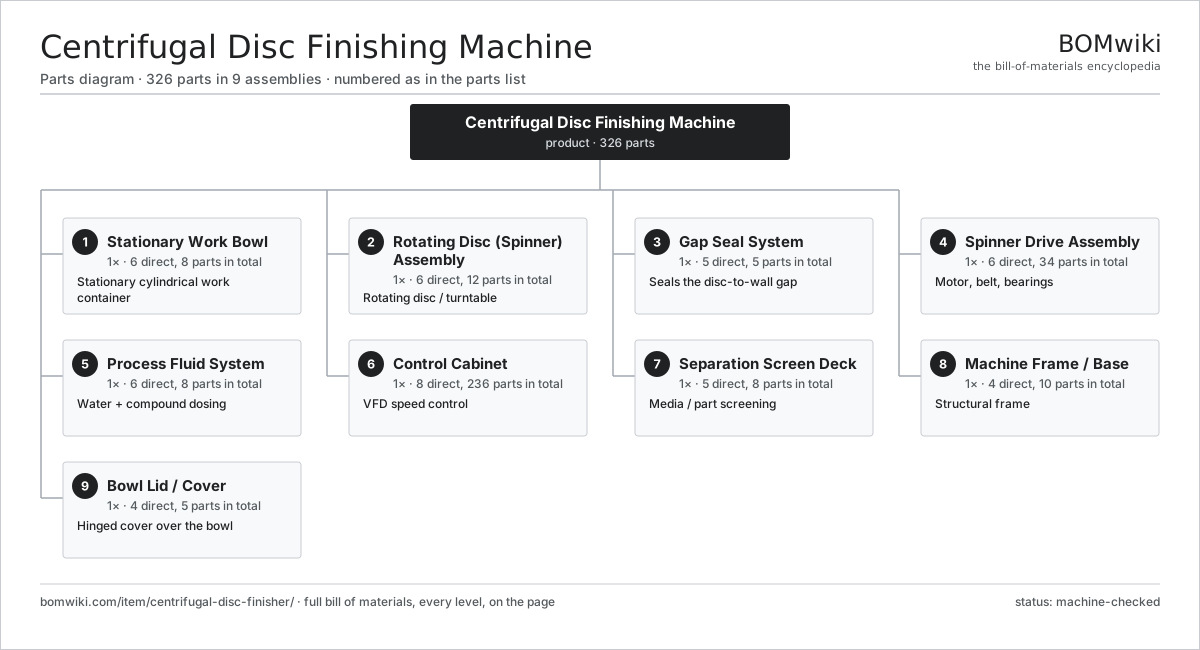
| # | Part | Qty | What it does |
|---|---|---|---|
| 1 | Stationary Work Bowl 6 parts | 1× | Stationary cylindrical work container |
| 2 | Rotating Disc (Spinner) Assembly 6 parts | 1× | Rotating disc / turntable |
| 3 | Gap Seal System 5 parts | 1× | Seals the disc-to-wall gap |
| 4 | Spinner Drive Assembly 6 parts | 1× | Motor, belt, bearings |
| 5 | Process Fluid System 6 parts | 1× | Water + compound dosing |
| 6 | Control Cabinet 8 parts | 1× | VFD speed control |
| 7 | Separation Screen Deck 5 parts | 1× | Media / part screening |
| 8 | Machine Frame / Base 4 parts | 1× | Structural frame |
| 9 | Bowl Lid / Cover 4 parts | 1× | Hinged cover over the bowl |
3D model
No 3D model yet. Have a CAD file of this? Add a 3D model — STL renders right on this page; STEP, FreeCAD, and OpenSCAD sources are welcome too (openly licensed, like all 3D models on BOMwiki).
Build & assembly graph
expand / collapse · shared sub-assemblies converge · links to related products · est. labourTap an assembly to expand/collapse · tap a part to open it · use “Open page” for any node · drag to pan, scroll to zoom.
Bill of materials for Centrifugal Disc Finishing Machine
9 top-level lines · 88 rows shown · 326 parts total · indented to 3 levels| # | Item / sub-assembly | Part no. | Qty/assy | Ext. qty | Parts | Type |
|---|---|---|---|---|---|---|
| 1 | Stationary Work Bowl 6 parts | centrifugal-disc-finisher-work-bowl | 1× | 1 | 8 | assembly |
| 1.1 | Bowl Shell | centrifugal-disc-finisher-bowl-shell | 1× | 1 | · | part |
| 1.2 | Bowl Wall Liner | centrifugal-disc-finisher-bowl-liner | 1× | 1 | · | part |
| 1.3 | Discharge Chute | centrifugal-disc-finisher-discharge-chute | 1× | 1 | · | part |
| 1.4 | Discharge Gate 3 parts | centrifugal-disc-finisher-discharge-gate | 1× | 1 | 3 | assembly |
| 1.4.1 | Gate Flap | centrifugal-disc-finisher-gate-flap | 1× | 1 | · | part |
| 1.4.2 | Gate Air Cylinder | centrifugal-disc-finisher-gate-cylinder | 1× | 1 | · | part |
| 1.4.3 | O-Ring Set | oring-set | 1× | 1 | · | part |
| 1.5 | Inspection Port | centrifugal-disc-finisher-inspection-port | 1× | 1 | · | part |
| 1.6 | Fastener Set | fastener-set | 1× | 1 | · | part |
| 2 | Rotating Disc (Spinner) Assembly 6 parts | centrifugal-disc-finisher-spinner-assembly | 1× | 1 | 12 | assembly |
| 2.1 | Spinner Disc | centrifugal-disc-finisher-spinner-disc | 1× | 1 | · | part |
| 2.2 | Spinner Top Liner | centrifugal-disc-finisher-spinner-liner | 1× | 1 | · | part |
| 2.3 | Spinner Hub | centrifugal-disc-finisher-spinner-hub | 1× | 1 | · | part |
| 2.4 | Spinner Shaft | centrifugal-disc-finisher-spinner-shaft | 1× | 1 | · | part |
| 2.5 | Spinner Bearing Housing 4 parts | centrifugal-disc-finisher-bearing-housing | 1× | 1 | 7 | assembly |
| 2.5.1 | Bearing Housing Body | centrifugal-disc-finisher-housing-body | 1× | 1 | · | part |
| 2.5.2 | Ball Bearing | ball-bearing | 2× | 2 | · | part |
| 2.5.3 | Oil Seal | oil-seal | 2× | 2 | · | part |
| 2.5.4 | Grease Fitting | centrifugal-disc-finisher-grease-fitting | 2× | 2 | · | part |
| 2.6 | Fastener Set | fastener-set | 1× | 1 | · | part |
| 3 | Gap Seal System 5 parts | centrifugal-disc-finisher-gap-seal-system | 1× | 1 | 5 | assembly |
| 3.1 | Gap Seal Ring | centrifugal-disc-finisher-gap-seal-ring | 1× | 1 | · | part |
| 3.2 | Seal Flush Channel | centrifugal-disc-finisher-seal-flush-channel | 1× | 1 | · | part |
| 3.3 | Seal Clamp Ring | centrifugal-disc-finisher-seal-clamp-ring | 1× | 1 | · | part |
| 3.4 | O-Ring Set | oring-set | 1× | 1 | · | part |
| 3.5 | Fastener Set | fastener-set | 1× | 1 | · | part |
| 4 | Spinner Drive Assembly 6 parts | centrifugal-disc-finisher-drive-assembly | 1× | 1 | 34 | assembly |
| 4.1 | Drive Motor 5 parts | centrifugal-disc-finisher-drive-motor | 1× | 1 | 26 | assembly |
| 4.1.1 | Stator Assembly 3 parts + deeper › | stator-assembly | 1× | 1 | 3 | assembly |
| 4.1.2 | Rotor Assembly 4 parts + deeper › | rotor-assembly | 1× | 1 | 19 | assembly |
| 4.1.3 | Motor Frame | centrifugal-disc-finisher-motor-frame | 1× | 1 | · | part |
| 4.1.4 | Ball Bearing | ball-bearing | 2× | 2 | · | part |
| 4.1.5 | Motor Cooling Fan | centrifugal-disc-finisher-cooling-fan | 1× | 1 | · | part |
| 4.2 | Drive Belt | drive-belt | 2× | 2 | · | part |
| 4.3 | Motor Pulley | centrifugal-disc-finisher-motor-pulley | 1× | 1 | · | part |
| 4.4 | Disc Pulley | centrifugal-disc-finisher-disc-pulley | 1× | 1 | · | part |
| 4.5 | Belt Tensioner 3 parts | centrifugal-disc-finisher-belt-tensioner | 1× | 1 | 3 | assembly |
| 4.5.1 | Tensioner Arm | centrifugal-disc-finisher-tensioner-arm | 1× | 1 | · | part |
| 4.5.2 | Ball Bearing | ball-bearing | 1× | 1 | · | part |
| 4.5.3 | Coil Spring | coil-spring | 1× | 1 | · | part |
| 4.6 | Belt Guard | centrifugal-disc-finisher-belt-guard | 1× | 1 | · | part |
| 5 | Process Fluid System 6 parts | centrifugal-disc-finisher-process-fluid-system | 1× | 1 | 8 | assembly |
| 5.1 | Water Solenoid Valve | centrifugal-disc-finisher-water-valve | 1× | 1 | · | part |
| 5.2 | Compound Dosing Pump 3 parts | centrifugal-disc-finisher-compound-pump | 1× | 1 | 3 | assembly |
| 5.2.1 | Dosing Pump Head | centrifugal-disc-finisher-pump-head | 1× | 1 | · | part |
| 5.2.2 | Dosing Pump Motor | centrifugal-disc-finisher-pump-motor | 1× | 1 | · | part |
| 5.2.3 | O-Ring Set | oring-set | 1× | 1 | · | part |
| 5.3 | Compound Tank | centrifugal-disc-finisher-compound-tank | 1× | 1 | · | part |
| 5.4 | Flow Manifold | centrifugal-disc-finisher-flow-manifold | 1× | 1 | · | part |
| 5.5 | Slurry Drain Valve | centrifugal-disc-finisher-drain-valve | 1× | 1 | · | part |
| 5.6 | Pressure Sensor | pressure-sensor | 1× | 1 | · | part |
| 6 | Control Cabinet 8 parts | centrifugal-disc-finisher-control-cabinet | 1× | 1 | 236 | assembly |
| 6.1 | Cabinet Enclosure | centrifugal-disc-finisher-cabinet-enclosure | 1× | 1 | · | part |
| 6.2 | Variable-Frequency Drive 4 parts | centrifugal-disc-finisher-vfd | 1× | 1 | 123 | assembly |
| 6.2.1 | Bare PCB | pcb-bare | 1× | 1 | · | part |
| 6.2.2 | Microcontroller | mcu | 1× | 1 | · | part |
| 6.2.3 | SMD Passive (R/C/L) | smd-passives | 120× | 120 | · | part |
| 6.2.4 | VFD Heatsink | centrifugal-disc-finisher-vfd-heatsink | 1× | 1 | · | part |
| 6.3 | PLC Module 4 parts | centrifugal-disc-finisher-plc | 1× | 1 | 100 | assembly |
| 6.3.1 | Bare PCB | pcb-bare | 1× | 1 | · | part |
| 6.3.2 | Microcontroller | mcu | 1× | 1 | · | part |
| 6.3.3 | Connector | connector | 8× | 8 | · | part |
| 6.3.4 | SMD Passive (R/C/L) | smd-passives | 90× | 90 | · | part |
| 6.4 | Power Supply | power-supply | 1× | 1 | · | part |
| 6.5 | Operator HMI Panel 3 parts | centrifugal-disc-finisher-hmi | 1× | 1 | 3 | assembly |
| 6.5.1 | LCD Panel | lcd-panel | 1× | 1 | · | part |
| 6.5.2 | Bare PCB | pcb-bare | 1× | 1 | · | part |
| 6.5.3 | Membrane Keypad | centrifugal-disc-finisher-membrane-keypad | 1× | 1 | · | part |
| 6.6 | Relay | relay | 6× | 6 | · | part |
| 6.7 | Wire Bundle | wire-bundle | 1× | 1 | · | part |
| 6.8 | Emergency Stop Button | centrifugal-disc-finisher-estop | 1× | 1 | · | part |
| 7 | Separation Screen Deck 5 parts | centrifugal-disc-finisher-separation-deck | 1× | 1 | 8 | assembly |
| 7.1 | Screen Frame | centrifugal-disc-finisher-screen-frame | 1× | 1 | · | part |
| 7.2 | Separation Screen Mesh | centrifugal-disc-finisher-screen-mesh | 1× | 1 | · | part |
| 7.3 | Vibratory Motor | centrifugal-disc-finisher-vibratory-motor | 1× | 1 | · | part |
| 7.4 | Coil Spring | coil-spring | 4× | 4 | · | part |
| 7.5 | Media Return Chute | centrifugal-disc-finisher-media-return-chute | 1× | 1 | · | part |
| 8 | Machine Frame / Base 4 parts | centrifugal-disc-finisher-frame-base | 1× | 1 | 10 | assembly |
| 8.1 | Base Weldment | centrifugal-disc-finisher-base-weldment | 1× | 1 | · | part |
| 8.2 | Leveling Foot | centrifugal-disc-finisher-leveling-foot | 4× | 4 | · | part |
| 8.3 | Sheet Metal Panel | sheet-panel | 4× | 4 | · | part |
| 8.4 | Fastener Set | fastener-set | 1× | 1 | · | part |
| 9 | Bowl Lid / Cover 4 parts | centrifugal-disc-finisher-lid | 1× | 1 | 5 | assembly |
| 9.1 | Lid Shell | centrifugal-disc-finisher-lid-shell | 1× | 1 | · | part |
| 9.2 | Lid Hinge | centrifugal-disc-finisher-lid-hinge | 2× | 2 | · | part |
| 9.3 | Lid Splash Seal | centrifugal-disc-finisher-lid-seal | 1× | 1 | · | part |
| 9.4 | Lid Safety Interlock | centrifugal-disc-finisher-lid-interlock | 1× | 1 | · | part |
Related products
same domain, ranked by shared parts Crankshaft Grinder
511 parts · shares 5 with this page
Crankshaft Grinder
511 parts · shares 5 with this page
 Creep-Feed Grinder
571 parts · shares 5 with this page
Creep-Feed Grinder
571 parts · shares 5 with this page
 Forging Trim Press
190 parts · shares 5 with this page
Industrial Sandblasting Machine
145 parts · shares 5 with this page
Forging Trim Press
190 parts · shares 5 with this page
Industrial Sandblasting Machine
145 parts · shares 5 with this page
 Railway Wheel Lathe
1,201 parts · shares 5 with this page
Railway Wheel Lathe
1,201 parts · shares 5 with this page
Sourcing: possible vendors
Prices, MOQ, and lead times are algorithmic estimates, not quotes, and not claims about these companies. Company mappings are curated by keyword; est. price band $10k–$1M. How estimates work| Vendor | HQ | Specialty | MOQ | Lead time |
|---|---|---|---|---|
|
🇩🇪DMG MORI
dmgmori.com ↗
|
Bielefeld, DE | Machine tools | 5 units | 12–20 wks |
|
🇯🇵Mazak
mazak.com ↗
|
Oguchi, JP | Machine tools | 5 units | 12–20 wks |
| haascnc.com ↗ | Oxnard, US | CNC machine tools | 5 units | 12–20 wks |
|
🇯🇵Okuma
okuma.com ↗
|
Niwa, JP | Machine tools | 5 units | 12–20 wks |
|
🇩🇪Trumpf
trumpf.com ↗
|
Ditzingen, DE | Laser & sheet-metal machines | 5 units | 12–20 wks |
1,036-word article