Keyseating Machine
ProductOverview
A keyseating machine cuts an internal keyway, the rectangular slot inside a bore that holds a drive key, using a single-point tool that reciprocates straight through the hole. It solves a specific problem: a key has to transmit torque between a shaft and a hub, and the matching slot inside the hub cannot be reached by a normal milling cutter or broach in many cases. A broach needs a press large enough to push it through in one pass and a separate broach for every width and length combination. The keyseating machine instead pushes a small Cutter Bar System through the bore on a Ram Assembly, shaving a thin layer on each downstroke and indexing the Feed System a few hundredths of a millimetre deeper each time. Over many strokes the slot grows to full depth. One tool covers a wide range of part sizes, which makes the machine valuable in job shops, gear works and repair facilities.
Base, column and ram
The structure is a grey iron Base and Column assembly. The Base Casting carries the worktable, and the Column rises behind it with hand-scraped ways that guide the ram vertically. Wear in those ways would let the slot drift out of square, so Way Gibs strips take up clearance and are reset periodically. The Ram is a hardened steel slide that rides the column on a Ram Slide Block and carries the cutter bar at its lower end. Because the bore depth varies from part to part, a Stroke Clamp sets how far the ram travels so it clears the work without wasting stroke. A Counterweight balances the moving mass, which lets the machine run smoothly at the upper end of its 40–120 stroke-per-minute range without shaking the slot.
Cutter bar and tool
The cutting work is done by the Cutter Bar System. A slender Tool Bar in 34CrMo4 alloy steel is passed through the workpiece bore and clamped to the ram with a Bar Clamp. At its tip sits a Cutter Insert, a single-point HSS or carbide tool ground to the keyway width. The bar is long and thin, so stiffness is the limiting factor: too aggressive a feed makes it deflect and the slot tapers or chatters. A Guide Bushing locates the bar concentric with the bore and supports it against the cutting load, which lets the operator take a heavier cut without losing accuracy. The cutter shears only on the downstroke; on the return stroke the bar lifts clear so the tool does not rub the freshly cut surface.
Feed system and indexing
Depth is built up by the Feed System. A Feed Screw advances the tool bar radially into the work, and it is driven by a Feed Ratchet that is indexed one increment per stroke by a Feed Pawl. The operator sets the increment on the Feed Dial, typically between 0.01 and 0.2 mm per stroke depending on the material and how rigid the setup is. Tougher alloys and longer bars call for a finer feed. This stroke-and-index principle is the same mechanism a slotter or shaper uses, applied here to internal work. Because the feed is mechanical and tied to the stroke, the slot deepens evenly and the cycle ends automatically when the dial reaches the target depth.
Workholding and multiple keyways
The Workholding system locates the part. A bored gear or pulley sits on the ground Worktable and is centred by one of a set of Bore Bushings sized to common bores, so the slot lands at the right place relative to the bore axis. A Clamp Set holds the part down against the upward cutting force. When a hub needs two or four keyways at exact spacing, as splined couplings and some gears do, a Indexing Fixture rotates the part by a precise angle between cuts. This is far quicker and more accurate than re-clamping and measuring for each slot, and it is the main reason the machine is preferred over a single broach when several slots are required.
Drive and coolant
Motion comes from the Drive System. A Drive Motor of 2–7.5 kW turns through a Helical Gearbox and Drive Belt, and a Crank and Connecting Link converts that rotation into the reciprocating ram stroke, running on Ball Bearing sets. The slender tool bar generates heat at the cutting tip and produces fine chips that can pack into the slot, so the Coolant System floods the zone. A Coolant Pump draws from the Coolant Tank in the base and feeds a Coolant Nozzle aimed into the bore, washing chips clear and keeping the tool cool enough to hold its edge through the cut.
Electrical control, materials and use
The Electrical System system is modest: a Motor Contactor switches the motor, a few Relay units handle the cycle logic, a Power Supply feeds the controls, and a Stroke Counter tracks progress and signals completion when full depth is reached. Castings are grey iron for damping; the ram and tool bar are alloy steels, hardened where they take wear. Keyseating machines are used to cut keyways in gears, sprockets, pulleys, couplings and repair parts where a key has to be added or recut. They handle bores from about 10 mm up to 300 mm and keyway widths to 50 mm, holding the slot to roughly H9 to JS9 tolerance. The combination of one flexible tool, mechanical indexing and optional rotary indexing makes the machine the standard choice for low and medium volume internal keyway work.
Keyseating Machine parts and their functions
8 top-level parts · 55 parts in total · full bill of materials below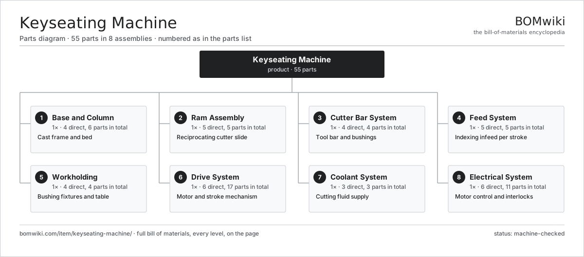
| # | Part | Qty | What it does |
|---|---|---|---|
| 1 | Base and Column 4 parts | 1× | Cast frame and bed |
| 2 | Ram Assembly 5 parts | 1× | Reciprocating cutter slide |
| 3 | Cutter Bar System 4 parts | 1× | Tool bar and bushings |
| 4 | Feed System 5 parts | 1× | Indexing infeed per stroke |
| 5 | Workholding 4 parts | 1× | Bushing fixtures and table |
| 6 | Drive System 6 parts | 1× | Motor and stroke mechanism |
| 7 | Coolant System 3 parts | 1× | Cutting fluid supply |
| 8 | Electrical System 6 parts | 1× | Motor control and interlocks |
3D model
No 3D model yet. Have a CAD file of this? Add a 3D model — STL renders right on this page; STEP, FreeCAD, and OpenSCAD sources are welcome too (openly licensed, like all 3D models on BOMwiki).
Build & assembly graph
expand / collapse · shared sub-assemblies converge · links to related products · est. labourTap an assembly to expand/collapse · tap a part to open it · use “Open page” for any node · drag to pan, scroll to zoom.
Bill of materials for Keyseating Machine
8 top-level lines · 49 rows shown · 55 parts total · indented to 3 levels| # | Item / sub-assembly | Part no. | Qty/assy | Ext. qty | Parts | Type |
|---|---|---|---|---|---|---|
| 1 | Base and Column 4 parts | keyseating-machine-base-column | 1× | 1 | 6 | assembly |
| 1.1 | Base Casting | keyseating-machine-base-casting | 1× | 1 | · | part |
| 1.2 | Column | keyseating-machine-column | 1× | 1 | · | part |
| 1.3 | Way Gibs | keyseating-machine-ways-gib | 2× | 2 | · | part |
| 1.4 | Fastener Set | fastener-set | 2× | 2 | · | part |
| 2 | Ram Assembly 5 parts | keyseating-machine-ram-assembly | 1× | 1 | 5 | assembly |
| 2.1 | Ram | keyseating-machine-ram | 1× | 1 | · | part |
| 2.2 | Ram Slide Block | keyseating-machine-ram-slide-block | 1× | 1 | · | part |
| 2.3 | Stroke Clamp | keyseating-machine-stroke-clamp | 1× | 1 | · | part |
| 2.4 | Counterweight | keyseating-machine-counterweight | 1× | 1 | · | part |
| 2.5 | Fastener Set | fastener-set | 1× | 1 | · | part |
| 3 | Cutter Bar System 4 parts | keyseating-machine-cutter-bar | 1× | 1 | 4 | assembly |
| 3.1 | Tool Bar | keyseating-machine-tool-bar | 1× | 1 | · | part |
| 3.2 | Cutter Insert | keyseating-machine-cutter-insert | 1× | 1 | · | part |
| 3.3 | Guide Bushing | keyseating-machine-guide-bushing | 1× | 1 | · | part |
| 3.4 | Bar Clamp | keyseating-machine-bar-clamp | 1× | 1 | · | part |
| 4 | Feed System 5 parts | keyseating-machine-feed-system | 1× | 1 | 5 | assembly |
| 4.1 | Feed Screw | keyseating-machine-feed-screw | 1× | 1 | · | part |
| 4.2 | Feed Ratchet | keyseating-machine-feed-ratchet | 1× | 1 | · | part |
| 4.3 | Feed Pawl | keyseating-machine-feed-pawl | 1× | 1 | · | part |
| 4.4 | Feed Dial | keyseating-machine-feed-dial | 1× | 1 | · | part |
| 4.5 | Fastener Set | fastener-set | 1× | 1 | · | part |
| 5 | Workholding 4 parts | keyseating-machine-workholding | 1× | 1 | 4 | assembly |
| 5.1 | Worktable | keyseating-machine-worktable | 1× | 1 | · | part |
| 5.2 | Bore Bushings | keyseating-machine-bore-bushings | 1× | 1 | · | part |
| 5.3 | Indexing Fixture | keyseating-machine-index-fixture | 1× | 1 | · | part |
| 5.4 | Clamp Set | keyseating-machine-clamp-set | 1× | 1 | · | part |
| 6 | Drive System 6 parts | keyseating-machine-drive-system | 1× | 1 | 17 | assembly |
| 6.1 | Drive Motor | keyseating-machine-drive-motor | 1× | 1 | · | part |
| 6.2 | Helical Gearbox 4 parts | gearbox | 1× | 1 | 9 | assembly |
| 6.2.1 | Helical Gear Pair | gear-pair | 2× | 2 | · | part |
| 6.2.2 | Gearbox Housing | gearbox-housing | 1× | 1 | · | part |
| 6.2.3 | Ball Bearing | ball-bearing | 4× | 4 | · | part |
| 6.2.4 | Oil Seal | oil-seal | 2× | 2 | · | part |
| 6.3 | Crank and Connecting Link | keyseating-machine-crank-link | 1× | 1 | · | part |
| 6.4 | Drive Belt | drive-belt | 1× | 1 | · | part |
| 6.5 | Ball Bearing | ball-bearing | 4× | 4 | · | part |
| 6.6 | Fastener Set | fastener-set | 1× | 1 | · | part |
| 7 | Coolant System 3 parts | keyseating-machine-coolant-system | 1× | 1 | 3 | assembly |
| 7.1 | Coolant Pump | keyseating-machine-coolant-pump | 1× | 1 | · | part |
| 7.2 | Coolant Tank | keyseating-machine-coolant-tank | 1× | 1 | · | part |
| 7.3 | Coolant Nozzle | keyseating-machine-coolant-nozzle | 1× | 1 | · | part |
| 8 | Electrical System 6 parts | keyseating-machine-electrical | 1× | 1 | 11 | assembly |
| 8.1 | Motor Contactor | keyseating-machine-contactor | 1× | 1 | · | part |
| 8.2 | Relay | relay | 2× | 2 | · | part |
| 8.3 | Stroke Counter | keyseating-machine-stroke-counter | 1× | 1 | · | part |
| 8.4 | Power Supply | power-supply | 1× | 1 | · | part |
| 8.5 | Wire Bundle | wire-bundle | 1× | 1 | · | part |
| 8.6 | Connector | connector | 5× | 5 | · | part |
Related products
same domain, ranked by shared parts Flat-Die Thread Roller
65 parts · shares 4 with this page
Roller Leveler
469 parts · shares 4 with this page
Slotting Machine
58 parts · shares 4 with this page
Strip Tension Leveler
513 parts · shares 4 with this page
Cut-to-Length Line
500 parts · shares 3 with this page
Roll Tapping Machine
82 parts · shares 3 with this page
Flat-Die Thread Roller
65 parts · shares 4 with this page
Roller Leveler
469 parts · shares 4 with this page
Slotting Machine
58 parts · shares 4 with this page
Strip Tension Leveler
513 parts · shares 4 with this page
Cut-to-Length Line
500 parts · shares 3 with this page
Roll Tapping Machine
82 parts · shares 3 with this page
Sourcing: possible vendors
Prices, MOQ, and lead times are algorithmic estimates, not quotes, and not claims about these companies. Company mappings are curated by keyword; est. price band $10k–$1M. How estimates work| Vendor | HQ | Specialty | MOQ | Lead time |
|---|---|---|---|---|
|
🇩🇪DMG MORI
dmgmori.com ↗
|
Bielefeld, DE | Machine tools | 5 units | 12–20 wks |
|
🇯🇵Mazak
mazak.com ↗
|
Oguchi, JP | Machine tools | 5 units | 12–20 wks |
| haascnc.com ↗ | Oxnard, US | CNC machine tools | 5 units | 12–20 wks |
|
🇯🇵Okuma
okuma.com ↗
|
Niwa, JP | Machine tools | 5 units | 12–20 wks |
|
🇩🇪Trumpf
trumpf.com ↗
|
Ditzingen, DE | Laser & sheet-metal machines | 5 units | 12–20 wks |
992-word article