Microfinishing Machine
ProductOverview
A microfinishing machine is the last metal-cutting step on precision rotating surfaces such as crankshaft and camshaft journals, bearing raceways, and sealing diameters. Grinding leaves a surface that looks smooth but is covered in microscopic peaks and valleys, with sharp peaks left by the grinding wheel grit. Those peaks carry the first load when a bearing or seal runs against the surface, so they wear quickly, score the mating part, and break down the oil film. Microfinishing removes the peaks and leaves a flat-topped, isotropic surface with a high bearing-area ratio, cutting Ra from around 0.2 micron after grinding down to 0.02 to 0.05 micron while taking only 1 to 5 micron off the radius.
The process is a form of superfinishing, but it differs from the older stone superfinishing method. Stone superfinishing presses a bonded abrasive stick against the part. Microfinishing instead uses a coated abrasive film, a polyester tape with a layer of graded Film Supply Spool grit, pressed against the rotating journal by a hard shoe. The film is advanced a few millimetres for every part, so each workpiece meets fresh, sharp abrasive and the result is consistent across thousands of parts. Two motions act at once: the part rotates while the shoe head oscillates along the axis, and the crossing of those two motions produces the fine isotropic crosshatch that the process is known for.
How It Works
The workpiece is held between the Workpiece Drive Headstock and the Tailstock and turned at 30 to 600 rpm. For each journal, a Oscillating Shoe Head closes around the surface and wraps a band of abrasive film over an arc of 90 to 180 degrees. The Contact Shoe backs the film and presses it into the surface under a regulated 50 to 500 N from the Shoe Pressure Cylinder. While the part rotates, the Oscillation Drive reciprocates the heads axially at 1 to 12 mm amplitude and 200 to 1500 cycles per minute. The two crossing motions abrade only the high peaks, since the conformable film and shoe ride on the existing surface and remove material fastest where it stands proudest.
A typical recipe runs in stages. A first pass with coarser film and higher pressure cuts the bulk of the peaks fast, then a finishing pass at lower pressure and finer grit refines the finish and rounds the remaining profile. Between parts the Abrasive Film Feed and Indexing Unit indexes 3 to 15 mm of fresh film through the Film Index Motor, so abrasive is used once and discarded. Shoe pressure, film grit, oscillation amplitude, and the number of revolutions are the levers the operator tunes to hit a target Ra and bearing ratio.
Subsystems
The Machine Base and Slides is a stress-relieved Base Casting carrying the heads on Shoe-Head Cross Slide cross slides and Linear Guide Rail rolling guides, with Leveling Mount feet setting the datum level. The Workpiece Drive Headstock drives the part through its Headstock Spindle and a Indexing Drive Chuck that, on crankshaft machines, indexes the part so the pin journals line up for their heads. The Tailstock presses a Live Center into the free end with its Tailstock Quill.
The Abrasive Film Feed and Indexing Unit manages the abrasive. Film runs from a Film Supply Spool over Film Guide Roller idlers and a Film Tension Arm dancer that holds back-tension, past the shoe, and onto a driven Film Take-Up Spool. A Film Pinch Clamp locks the film during the cut and releases it to index. Each Oscillating Shoe Head carries the Contact Shoe on a hinged Shoe Clamping Arm pivoting on a Shoe Hinge Pin, and on camshaft work a Lobe-Following Linkage linkage lets the shoe track the cam lobe profile as the part turns so contact stays on the flanks and nose. A Pressure Sensor closes the loop on shoe force.
The Oscillation Drive generates the axial motion through an adjustable Eccentric Shaft, a Oscillation Motor, and a Oscillation Yoke driven by a Drive Belt. The Coolant and Filtration System floods the contact with 20 to 80 L/min of light oil from a Coolant Pump, cleaned by a Coolant Filter and a Magnetic Separator so the cut peaks do not recirculate and score the surface. The Control Cabinet ties it together: the Cycle Controller sequences the recipe through Servo Drive amplifiers, the Operator Panel holds the part recipes, and a Surface Roughness Gauge checks Ra and bearing ratio on sampled parts.
Materials and Consumables
The base is grey cast iron for damping and dimensional stability. Spindles and centers run on a Ball Bearing set with an Oil Seal keeping coolant out. The single consumable that defines the result is the film: a polyester backing coated with graded aluminium-oxide or diamond grit, with the grit size chosen for the target finish, 30 micron for fast peak removal and 9 micron or finer for mirror finishes. Contact shoes are faced with hard bronze or filled PTFE so they conform to the journal without cutting it themselves, and they are shaped to the journal radius. The coolant is a light mineral oil chosen to flush the fine swarf rather than to cool, since the process generates little heat.
Variants
Machines range from single-head units for a bearing-race line up to 12-head machines that finish every main and pin journal of an engine crankshaft in one cycle of 20 to 60 seconds. Camshaft machines add the Lobe-Following Linkage linkage and synchronise oscillation to part angle so the shoe follows the non-round lobe. High-volume engine-plant machines include a Automatic Part Loader with a Load Gantry and Part Gripper so the cell runs unattended. Standalone machines for repair shops are loaded by hand and finish one journal at a time. Some machines combine microfinishing with a preceding grinding station so a part is ground and finished in one setup.
Use
Microfinishing is standard on automotive and diesel crankshafts and camshafts, on rolling-element bearing rings before they meet the Ball Bearing grinding line, on hydraulic rod and pump surfaces, and on any sealing diameter that runs against an Oil Seal. The payoff is longer bearing life, lower friction, less break-in wear, and a surface that holds an oil film. Because the process removes only a few microns and corrects almost no form error, the part must arrive already ground to size and round, and the microfinishing machine simply takes the rough top layer off and leaves the bearing surface the engine or pump needs.
Microfinishing Machine parts and their functions
9 top-level parts · 207 parts in total · full bill of materials below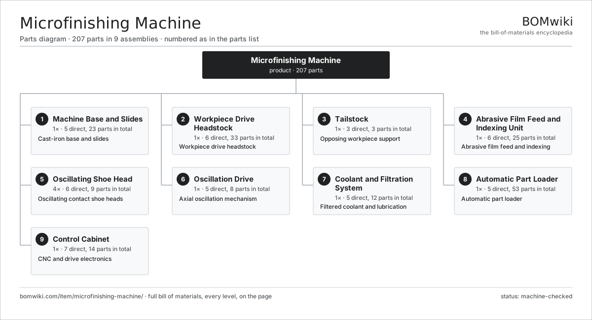
| # | Part | Qty | What it does |
|---|---|---|---|
| 1 | Machine Base and Slides 5 parts | 1× | Cast-iron base and slides |
| 2 | Workpiece Drive Headstock 6 parts | 1× | Workpiece drive headstock |
| 3 | Tailstock 3 parts | 1× | Opposing workpiece support |
| 4 | Abrasive Film Feed and Indexing Unit 6 parts | 1× | Abrasive film feed and indexing |
| 5 | Oscillating Shoe Head 6 parts | 4× | Oscillating contact shoe heads |
| 6 | Oscillation Drive 5 parts | 1× | Axial oscillation mechanism |
| 7 | Coolant and Filtration System 5 parts | 1× | Filtered coolant and lubrication |
| 8 | Automatic Part Loader 5 parts | 1× | Automatic part loader |
| 9 | Control Cabinet 7 parts | 1× | CNC and drive electronics |
3D model
No 3D model yet. Have a CAD file of this? Add a 3D model — STL renders right on this page; STEP, FreeCAD, and OpenSCAD sources are welcome too (openly licensed, like all 3D models on BOMwiki).
Build & assembly graph
expand / collapse · shared sub-assemblies converge · links to related products · est. labourTap an assembly to expand/collapse · tap a part to open it · use “Open page” for any node · drag to pan, scroll to zoom.
Bill of materials for Microfinishing Machine
9 top-level lines · 65 rows shown · 207 parts total · indented to 3 levels| # | Item / sub-assembly | Part no. | Qty/assy | Ext. qty | Parts | Type |
|---|---|---|---|---|---|---|
| 1 | Machine Base and Slides 5 parts | mfm-machine-base | 1× | 1 | 23 | assembly |
| 1.1 | Base Casting | mfm-base-casting | 1× | 1 | · | part |
| 1.2 | Shoe-Head Cross Slide | mfm-linear-slide | 4× | 4 | · | part |
| 1.3 | Linear Guide Rail | linear-guide | 8× | 8 | · | part |
| 1.4 | Leveling Mount | mfm-leveling-mount | 6× | 6 | · | part |
| 1.5 | Way Cover | mfm-way-cover | 4× | 4 | · | part |
| 2 | Workpiece Drive Headstock 6 parts | mfm-headstock | 1× | 1 | 33 | assembly |
| 2.1 | Headstock Spindle | mfm-headstock-spindle | 1× | 1 | · | part |
| 2.2 | Indexing Drive Chuck | mfm-drive-chuck | 1× | 1 | · | part |
| 2.3 | Servo Motor 4 parts | servo-motor | 1× | 1 | 24 | assembly |
| 2.3.1 | Stator Assembly 3 parts + deeper › | stator-assembly | 1× | 1 | 3 | assembly |
| 2.3.2 | Rotor Assembly 4 parts + deeper › | rotor-assembly | 1× | 1 | 19 | assembly |
| 2.3.3 | Encoder | encoder | 1× | 1 | · | part |
| 2.3.4 | Motor Housing | motor-housing | 1× | 1 | · | part |
| 2.4 | Helical Gear Pair | gear-pair | 1× | 1 | · | part |
| 2.5 | Ball Bearing | ball-bearing | 4× | 4 | · | part |
| 2.6 | Oil Seal | oil-seal | 2× | 2 | · | part |
| 3 | Tailstock 3 parts | mfm-tailstock | 1× | 1 | 3 | assembly |
| 3.1 | Tailstock Quill | mfm-tailstock-quill | 1× | 1 | · | part |
| 3.2 | Live Center | mfm-live-center | 1× | 1 | · | part |
| 3.3 | Tailstock Base Clamp | mfm-tailstock-clamp | 1× | 1 | · | part |
| 4 | Abrasive Film Feed and Indexing Unit 6 parts | mfm-film-feed-unit | 1× | 1 | 25 | assembly |
| 4.1 | Film Supply Spool | mfm-film-supply-spool | 4× | 4 | · | part |
| 4.2 | Film Take-Up Spool | mfm-film-takeup-spool | 4× | 4 | · | part |
| 4.3 | Film Index Motor | mfm-film-index-motor | 1× | 1 | · | part |
| 4.4 | Film Guide Roller | mfm-film-guide-roller | 8× | 8 | · | part |
| 4.5 | Film Tension Arm | mfm-film-tension-arm | 4× | 4 | · | part |
| 4.6 | Film Pinch Clamp | mfm-film-clamp | 4× | 4 | · | part |
| 5 | Oscillating Shoe Head 6 parts | mfm-shoe-head-set | 4× | 4 | 9 | assembly |
| 5.1 | Contact Shoe | mfm-contact-shoe | 2× | 8 | · | part |
| 5.2 | Shoe Clamping Arm | mfm-shoe-arm | 2× | 8 | · | part |
| 5.3 | Shoe Pressure Cylinder | mfm-pressure-cylinder | 1× | 4 | · | part |
| 5.4 | Lobe-Following Linkage | mfm-lobe-follower | 1× | 4 | · | part |
| 5.5 | Pressure Sensor | pressure-sensor | 1× | 4 | · | part |
| 5.6 | Shoe Hinge Pin | mfm-shoe-hinge-pin | 2× | 8 | · | part |
| 6 | Oscillation Drive 5 parts | mfm-oscillation-drive | 1× | 1 | 8 | assembly |
| 6.1 | Eccentric Shaft | mfm-eccentric-shaft | 1× | 1 | · | part |
| 6.2 | Oscillation Motor | mfm-oscillation-motor | 1× | 1 | · | part |
| 6.3 | Oscillation Yoke | mfm-oscillation-yoke | 1× | 1 | · | part |
| 6.4 | Drive Belt | drive-belt | 1× | 1 | · | part |
| 6.5 | Ball Bearing | ball-bearing | 4× | 4 | · | part |
| 7 | Coolant and Filtration System 5 parts | mfm-coolant-system | 1× | 1 | 12 | assembly |
| 7.1 | Coolant Pump | mfm-coolant-pump | 1× | 1 | · | part |
| 7.2 | Coolant Tank | mfm-coolant-tank | 1× | 1 | · | part |
| 7.3 | Coolant Filter | mfm-coolant-filter | 1× | 1 | · | part |
| 7.4 | Magnetic Separator | mfm-magnetic-separator | 1× | 1 | · | part |
| 7.5 | Coolant Nozzle | mfm-coolant-nozzle | 8× | 8 | · | part |
| 8 | Automatic Part Loader 5 parts | mfm-loader | 1× | 1 | 53 | assembly |
| 8.1 | Load Gantry | mfm-load-gantry | 1× | 1 | · | part |
| 8.2 | Part Gripper | mfm-load-gripper | 2× | 2 | · | part |
| 8.3 | Staging Cradle | mfm-part-cradle | 1× | 1 | · | part |
| 8.4 | Servo Motor 4 parts | servo-motor | 2× | 2 | 24 | assembly |
| 8.4.1 | Stator Assembly 3 parts + deeper › | stator-assembly | 1× | 2 | 3 | assembly |
| 8.4.2 | Rotor Assembly 4 parts + deeper › | rotor-assembly | 1× | 2 | 19 | assembly |
| 8.4.3 | Encoder | encoder | 1× | 2 | · | part |
| 8.4.4 | Motor Housing | motor-housing | 1× | 2 | · | part |
| 8.5 | Ball Screw | ball-screw | 1× | 1 | · | part |
| 9 | Control Cabinet 7 parts | mfm-control-cabinet | 1× | 1 | 14 | assembly |
| 9.1 | Cycle Controller | mfm-cnc-unit | 1× | 1 | · | part |
| 9.2 | Servo Drive | mfm-servo-drive | 3× | 3 | · | part |
| 9.3 | Power Supply | power-supply | 1× | 1 | · | part |
| 9.4 | Operator Panel | mfm-operator-panel | 1× | 1 | · | part |
| 9.5 | Surface Roughness Gauge | mfm-surface-gauge | 1× | 1 | · | part |
| 9.6 | Relay | relay | 6× | 6 | · | part |
| 9.7 | Wire Bundle | wire-bundle | 1× | 1 | · | part |
Related products
same domain, ranked by shared parts Bevel Gear Generator
201 parts · shares 5 with this page
Cold Rolling Mill
991 parts · shares 5 with this page
Bevel Gear Generator
201 parts · shares 5 with this page
Cold Rolling Mill
991 parts · shares 5 with this page
 Crankshaft Grinder
511 parts · shares 5 with this page
Crankshaft Grinder
511 parts · shares 5 with this page
 Creep-Feed Grinder
571 parts · shares 5 with this page
Double-Disc Grinder
153 parts · shares 5 with this page
Creep-Feed Grinder
571 parts · shares 5 with this page
Double-Disc Grinder
153 parts · shares 5 with this page
Sourcing: possible vendors
Prices, MOQ, and lead times are algorithmic estimates, not quotes, and not claims about these companies. Company mappings are curated by keyword; est. price band $10k–$1M. How estimates work| Vendor | HQ | Specialty | MOQ | Lead time |
|---|---|---|---|---|
|
🇩🇪DMG MORI
dmgmori.com ↗
|
Bielefeld, DE | Machine tools | 5 units | 12–20 wks |
|
🇯🇵Mazak
mazak.com ↗
|
Oguchi, JP | Machine tools | 5 units | 12–20 wks |
| haascnc.com ↗ | Oxnard, US | CNC machine tools | 5 units | 12–20 wks |
|
🇯🇵Okuma
okuma.com ↗
|
Niwa, JP | Machine tools | 5 units | 12–20 wks |
|
🇩🇪Trumpf
trumpf.com ↗
|
Ditzingen, DE | Laser & sheet-metal machines | 5 units | 12–20 wks |
1,119-word article