Sealed Quench Furnace
ProductOverview
A sealed quench furnace, also called an integral quench furnace, carburizes steel parts and then quenches them in oil without ever exposing the hot, freshly treated metal to air. Carburizing diffuses carbon into the surface of low-carbon steel at high temperature so that, after quenching, the part has a hard wearing case over a tough core. Doing this in one sealed machine matters because a carburized part pulled into open air would oxidize and lose carbon from the very surface that was just enriched, and it would start cooling before it reached the quench. The furnace solves both problems by holding the work in a carbon-rich protective atmosphere from the moment it enters until it is under the oil.
The machine is built around a hot Heating Chamber where carburizing happens, a Vestibule at the front that buffers the hot zone from room air, and a Quench Tank of oil directly below the vestibule. The Atmosphere System supplies and controls the gas, the Heating System supplies the heat, the Transfer Mechanism moves the charge between chambers, the Door System seal each stage, and the Control System runs the recipe.
How the cycle runs
A basket of parts sits on a Charge Tray and enters through the Outer Door into the vestibule, which is then purged. The Inner Door opens and the Pusher drives the tray into the hot zone. There the load soaks at temperature in the carburizing atmosphere for a time set by the required case depth, since carbon diffuses deeper the longer it is held. When the case is grown, the controller can drop the carbon potential for a diffusion step to flatten the carbon gradient. The pusher then pulls the tray back into the vestibule, the inner door closes, and the Load Elevator lowers the whole tray into the oil. The Flame Curtain burns off atmosphere that escapes when the outer door opens to remove the quenched load.
Heating chamber
The Heating Chamber is a welded Chamber Shell lined with a Refractory Lining of ceramic Fiber Module blocks over insulating Insulating Firebrick, held to the shell by alloy Refractory Anchor studs. The charge rides on Hearth Rail of heat-resistant alloy. A key part is the Recirculation Fan, because a still atmosphere would carburize the outside of the load faster than the center. Its Fan Impeller of cast nickel alloy, carried on a Fan Shaft through a water-cooled Fan Bearing Housing, stirs the gas so every surface sees the same carbon potential, with Flow Baffle plates guiding the flow around the parts.
Atmosphere and carbon control
The Atmosphere System is what makes carburizing happen. An Endothermic Generator cracks natural gas and air in a heated Catalyst Retort packed with Nickel Catalyst, then a Gas Cooler chills the result to freeze its composition. This carrier gas, rich in carbon monoxide and hydrogen, is the base atmosphere. To raise the carbon potential, the Enrichment Train meters in a hydrocarbon through the Enrichment Valve and Gas Mixer. A zirconia Carbon Probe reads the oxygen activity in the hot zone, and the Carbon Controller uses that reading to trim enrichment so the surface carbon stays on target through the cycle. Get this wrong and the case is too shallow, too rich, or laced with carbides, so the probe and controller are central to part quality.
Heating system
Because flue gas must never mix with the carburizing atmosphere, the furnace heats through sealed Radiant Tube elements. Each tube is fired by a Tube Burner and radiates heat into the chamber while keeping combustion products on the inside of the tube. A Recuperator reclaims flue heat to preheat combustion air and cut fuel use. The Thermocouple sensors report chamber temperature to the controller, and a Gas Valve Train provides safe shutoff and regulation of the burner fuel. Electric versions swap the tubes for radiant electric elements but keep the same sealed principle.
Transfer, quench, and doors
The Transfer Mechanism moves the load with a hydraulic Pusher, whose Push Rod and Push Cylinder are fed by the Hydraulic Power Unit with its Hydraulic Pump, Oil Reservoir, and Directional Valve block. The Quench Tank holds heat-treat oil kept moving by the Oil Agitator and held at temperature by the Oil Heater, with an Oil Cooler and Oil Pump removing the heat each load adds. The Door Seal on each door, lifted by a Door Cylinder, keeps the atmosphere in and air out.
Use, variants, and limits
Sealed quench furnaces are the workhorse of commercial and captive heat-treat shops, hardening gears, shafts, bearing races, fasteners, and tooling in batches. Variants differ in size, in gas-fired versus electric heating, and in whether they run carburizing, carbonitriding, or neutral hardening recipes, all under the same Control System. The limits follow from the design: oil quenching distorts parts more than gas quenching, the carbon-rich atmosphere is flammable and demands the Flame Curtain and Safety Relay interlocks, and case depth grows slowly so deep cases mean long cycles and high fuel cost. For very low distortion or for cleaner operation, shops move to vacuum carburizing with high-pressure gas quench, but for general case hardening at moderate cost the sealed quench furnace remains the standard machine.
Sealed Quench Furnace parts and their functions
8 top-level parts · 185 parts in total · full bill of materials below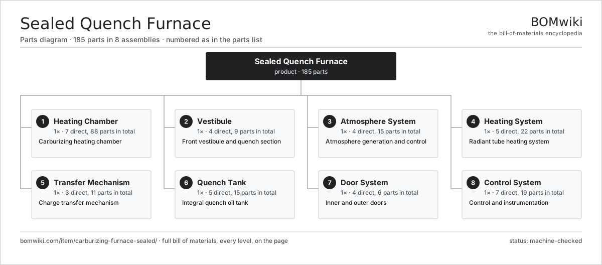
| # | Part | Qty | What it does |
|---|---|---|---|
| 1 | Heating Chamber 7 parts | 1× | Carburizing heating chamber |
| 2 | Vestibule 4 parts | 1× | Front vestibule and quench section |
| 3 | Atmosphere System 4 parts | 1× | Atmosphere generation and control |
| 4 | Heating System 5 parts | 1× | Radiant tube heating system |
| 5 | Transfer Mechanism 3 parts | 1× | Charge transfer mechanism |
| 6 | Quench Tank 5 parts | 1× | Integral quench oil tank |
| 7 | Door System 4 parts | 1× | Inner and outer doors |
| 8 | Control System 7 parts | 1× | Control and instrumentation |
3D model
No 3D model yet. Have a CAD file of this? Add a 3D model — STL renders right on this page; STEP, FreeCAD, and OpenSCAD sources are welcome too (openly licensed, like all 3D models on BOMwiki).
Build & assembly graph
expand / collapse · shared sub-assemblies converge · links to related products · est. labourTap an assembly to expand/collapse · tap a part to open it · use “Open page” for any node · drag to pan, scroll to zoom.
Bill of materials for Sealed Quench Furnace
8 top-level lines · 83 rows shown · 185 parts total · indented to 3 levels| # | Item / sub-assembly | Part no. | Qty/assy | Ext. qty | Parts | Type |
|---|---|---|---|---|---|---|
| 1 | Heating Chamber 7 parts | carburizing-furnace-sealed-heating-chamber | 1× | 1 | 88 | assembly |
| 1.1 | Chamber Shell | carburizing-furnace-sealed-shell | 1× | 1 | · | part |
| 1.2 | Refractory Lining 3 parts | carburizing-furnace-sealed-refractory | 1× | 1 | 73 | assembly |
| 1.2.1 | Fiber Module | carburizing-furnace-sealed-fiber-module | 24× | 24 | · | part |
| 1.2.2 | Insulating Firebrick | carburizing-furnace-sealed-firebrick | 1× | 1 | · | part |
| 1.2.3 | Refractory Anchor | carburizing-furnace-sealed-anchor | 48× | 48 | · | part |
| 1.3 | Hearth Rail | carburizing-furnace-sealed-hearth-rails | 2× | 2 | · | part |
| 1.4 | Recirculation Fan 4 parts | carburizing-furnace-sealed-recirc-fan | 1× | 1 | 5 | assembly |
| 1.4.1 | Fan Impeller | carburizing-furnace-sealed-fan-impeller | 1× | 1 | · | part |
| 1.4.2 | Fan Shaft | carburizing-furnace-sealed-fan-shaft | 1× | 1 | · | part |
| 1.4.3 | Fan Motor | carburizing-furnace-sealed-fan-motor | 1× | 1 | · | part |
| 1.4.4 | Ball Bearing | ball-bearing | 2× | 2 | · | part |
| 1.5 | Fan Bearing Housing | carburizing-furnace-sealed-fan-bearing | 2× | 2 | · | part |
| 1.6 | Flow Baffle | carburizing-furnace-sealed-baffle | 4× | 4 | · | part |
| 1.7 | Fastener Set | fastener-set | 1× | 1 | · | part |
| 2 | Vestibule 4 parts | carburizing-furnace-sealed-vestibule | 1× | 1 | 9 | assembly |
| 2.1 | Vestibule Shell | carburizing-furnace-sealed-vestibule-shell | 1× | 1 | · | part |
| 2.2 | Load Elevator 5 parts | carburizing-furnace-sealed-elevator | 1× | 1 | 6 | assembly |
| 2.2.1 | Elevator Frame | carburizing-furnace-sealed-elevator-frame | 1× | 1 | · | part |
| 2.2.2 | Lift Chain | carburizing-furnace-sealed-elevator-chain | 2× | 2 | · | part |
| 2.2.3 | Elevator Drive | carburizing-furnace-sealed-elevator-motor | 1× | 1 | · | part |
| 2.2.4 | Helical Gear Pair | gear-pair | 1× | 1 | · | part |
| 2.2.5 | Gearbox Housing | gearbox-housing | 1× | 1 | · | part |
| 2.3 | Flame Curtain | carburizing-furnace-sealed-flame-curtain | 1× | 1 | · | part |
| 2.4 | Vestibule Cooler | carburizing-furnace-sealed-vestibule-cooler | 1× | 1 | · | part |
| 3 | Atmosphere System 4 parts | carburizing-furnace-sealed-atmosphere | 1× | 1 | 15 | assembly |
| 3.1 | Endothermic Generator 4 parts | carburizing-furnace-sealed-endo-generator | 1× | 1 | 7 | assembly |
| 3.1.1 | Catalyst Retort | carburizing-furnace-sealed-retort | 1× | 1 | · | part |
| 3.1.2 | Nickel Catalyst | carburizing-furnace-sealed-catalyst | 1× | 1 | · | part |
| 3.1.3 | Gas Cooler | carburizing-furnace-sealed-gas-cooler | 1× | 1 | · | part |
| 3.1.4 | Heating Element | heating-element | 4× | 4 | · | part |
| 3.2 | Enrichment Train 3 parts | carburizing-furnace-sealed-enrich-train | 1× | 1 | 4 | assembly |
| 3.2.1 | Enrichment Valve | carburizing-furnace-sealed-enrich-valve | 2× | 2 | · | part |
| 3.2.2 | Gas Mixer | carburizing-furnace-sealed-mixer | 1× | 1 | · | part |
| 3.2.3 | Pressure Sensor | pressure-sensor | 1× | 1 | · | part |
| 3.3 | Carbon Probe | carburizing-furnace-sealed-carbon-probe | 1× | 1 | · | part |
| 3.4 | Flow Meter | carburizing-furnace-sealed-flow-meter | 3× | 3 | · | part |
| 4 | Heating System 5 parts | carburizing-furnace-sealed-heating-system | 1× | 1 | 22 | assembly |
| 4.1 | Radiant Tube | carburizing-furnace-sealed-radiant-tube | 8× | 8 | · | part |
| 4.2 | Tube Burner | carburizing-furnace-sealed-tube-burner | 8× | 8 | · | part |
| 4.3 | Recuperator | carburizing-furnace-sealed-recuperator | 1× | 1 | · | part |
| 4.4 | Thermocouple | carburizing-furnace-sealed-thermocouple | 4× | 4 | · | part |
| 4.5 | Gas Valve Train | carburizing-furnace-sealed-gas-valve-train | 1× | 1 | · | part |
| 5 | Transfer Mechanism 3 parts | carburizing-furnace-sealed-transfer | 1× | 1 | 11 | assembly |
| 5.1 | Pusher 3 parts | carburizing-furnace-sealed-pusher | 1× | 1 | 4 | assembly |
| 5.1.1 | Push Rod | carburizing-furnace-sealed-push-rod | 1× | 1 | · | part |
| 5.1.2 | Push Cylinder | carburizing-furnace-sealed-push-cylinder | 1× | 1 | · | part |
| 5.1.3 | Oil Seal | oil-seal | 2× | 2 | · | part |
| 5.2 | Charge Tray | carburizing-furnace-sealed-tray | 1× | 1 | · | part |
| 5.3 | Hydraulic Power Unit 3 parts | carburizing-furnace-sealed-hyd-power-unit | 1× | 1 | 6 | assembly |
| 5.3.1 | Hydraulic Pump | carburizing-furnace-sealed-hyd-pump | 1× | 1 | · | part |
| 5.3.2 | Oil Reservoir | carburizing-furnace-sealed-hyd-reservoir | 1× | 1 | · | part |
| 5.3.3 | Directional Valve | carburizing-furnace-sealed-hyd-valve | 4× | 4 | · | part |
| 6 | Quench Tank 5 parts | carburizing-furnace-sealed-quench-tank | 1× | 1 | 15 | assembly |
| 6.1 | Tank Body | carburizing-furnace-sealed-tank-body | 1× | 1 | · | part |
| 6.2 | Oil Agitator 4 parts | carburizing-furnace-sealed-agitator | 2× | 2 | 5 | assembly |
| 6.2.1 | Agitator Propeller | carburizing-furnace-sealed-agitator-prop | 1× | 2 | · | part |
| 6.2.2 | Agitator Motor | carburizing-furnace-sealed-agitator-motor | 1× | 2 | · | part |
| 6.2.3 | Ball Bearing | ball-bearing | 2× | 4 | · | part |
| 6.2.4 | Oil Seal | oil-seal | 1× | 2 | · | part |
| 6.3 | Oil Heater | carburizing-furnace-sealed-oil-heater | 2× | 2 | · | part |
| 6.4 | Oil Cooler | carburizing-furnace-sealed-oil-cooler | 1× | 1 | · | part |
| 6.5 | Oil Pump | carburizing-furnace-sealed-oil-pump | 1× | 1 | · | part |
| 7 | Door System 4 parts | carburizing-furnace-sealed-doors | 1× | 1 | 6 | assembly |
| 7.1 | Inner Door | carburizing-furnace-sealed-inner-door | 1× | 1 | · | part |
| 7.2 | Outer Door | carburizing-furnace-sealed-outer-door | 1× | 1 | · | part |
| 7.3 | Door Cylinder | carburizing-furnace-sealed-door-cylinder | 2× | 2 | · | part |
| 7.4 | Door Seal | carburizing-furnace-sealed-door-seal | 2× | 2 | · | part |
| 8 | Control System 7 parts | carburizing-furnace-sealed-control | 1× | 1 | 19 | assembly |
| 8.1 | PLC 4 parts | carburizing-furnace-sealed-plc | 1× | 1 | 7 | assembly |
| 8.1.1 | Bare PCB | pcb-bare | 1× | 1 | · | part |
| 8.1.2 | Microcontroller | mcu | 1× | 1 | · | part |
| 8.1.3 | SMD Passive (R/C/L) | smd-passives | 1× | 1 | · | part |
| 8.1.4 | Relay | relay | 4× | 4 | · | part |
| 8.2 | Carbon Controller | carburizing-furnace-sealed-carbon-controller | 1× | 1 | · | part |
| 8.3 | Operator Panel 3 parts | carburizing-furnace-sealed-hmi | 1× | 1 | 3 | assembly |
| 8.3.1 | LCD Panel | lcd-panel | 1× | 1 | · | part |
| 8.3.2 | Bare PCB | pcb-bare | 1× | 1 | · | part |
| 8.3.3 | Microcontroller | mcu | 1× | 1 | · | part |
| 8.4 | Safety Relay | carburizing-furnace-sealed-safety-relay | 2× | 2 | · | part |
| 8.5 | Power Supply | power-supply | 1× | 1 | · | part |
| 8.6 | Wire Bundle | wire-bundle | 1× | 1 | · | part |
| 8.7 | Connector | connector | 4× | 4 | · | part |
Related products
same domain, ranked by shared parts Continuous Belt Furnace
130 parts · shares 4 with this page
Quench Tank System
93 parts · shares 4 with this page
Continuous Belt Furnace
130 parts · shares 4 with this page
Quench Tank System
93 parts · shares 4 with this page
 Rotary-Table Surface Grinder
172 parts · shares 4 with this page
Rotary-Table Surface Grinder
172 parts · shares 4 with this page
 Crankshaft Grinder
511 parts · shares 3 with this page
Crankshaft Grinder
511 parts · shares 3 with this page
 Profile Grinding Machine
815 parts · shares 3 with this page
Profile Grinding Machine
815 parts · shares 3 with this page
 Aluminum Extrusion Press
365 parts · shares 2 with this page
Aluminum Extrusion Press
365 parts · shares 2 with this page
Sourcing: possible vendors
Prices, MOQ, and lead times are algorithmic estimates, not quotes, and not claims about these companies. Company mappings are curated by keyword; est. price band $10k–$1M. How estimates work| Vendor | HQ | Specialty | MOQ | Lead time |
|---|---|---|---|---|
|
🇩🇪DMG MORI
dmgmori.com ↗
|
Bielefeld, DE | Machine tools | 5 units | 12–20 wks |
|
🇯🇵Mazak
mazak.com ↗
|
Oguchi, JP | Machine tools | 5 units | 12–20 wks |
| haascnc.com ↗ | Oxnard, US | CNC machine tools | 5 units | 12–20 wks |
|
🇯🇵Okuma
okuma.com ↗
|
Niwa, JP | Machine tools | 5 units | 12–20 wks |
|
🇩🇪Trumpf
trumpf.com ↗
|
Ditzingen, DE | Laser & sheet-metal machines | 5 units | 12–20 wks |
1,032-word article