CO2 Laser Cutting Machine
ProductOverview
A CO2 laser cutting machine cuts sheet and plate by focusing an infrared laser beam to a tiny spot that melts or burns through the material, while a jet of assist gas blows the molten metal out of the cut. The beam comes from a sealed gas resonator filled with carbon dioxide, and it works at a wavelength of 10.6 micrometres, far out in the infrared where ordinary glass is opaque. That single fact shapes the whole machine: the beam cannot travel in fibre or pass through normal lenses, so it is steered by metal mirrors and focused by special infrared optics all the way to the work. The machine cuts mild steel, stainless, and aluminium, and unlike most metal lasers it also cuts non-metals such as acrylic, wood, and plastics cleanly, which keeps CO2 sources in service for mixed work.
The machine has nine major parts. The Machine Frame and Bed carries everything and supports the sheet. The CO2 Laser Resonator makes the beam. The Beam Delivery and Cutting Head carries that beam to the work and focuses it. The Gantry Motion System flies the cutting head over the sheet, the Assist Gas System feeds assist gas to the cut, the Water Chiller keeps the source cool, the CNC Controller and HMI runs the program, the Fume Extraction clears the smoke, and the Safety Enclosure keeps the beam contained.
The laser source
The beam is born in the CO2 Laser Resonator. At its centre is a CO2 Gas Tube holding the Laser Gas Mixture, a blend of carbon dioxide, nitrogen, and helium. Nitrogen takes energy from the electrical discharge and hands it to the carbon dioxide, the carbon dioxide is what actually emits the laser light, and helium carries waste heat to the wall and keeps the discharge stable. To drive the gas, the RF Power Supply feeds radio-frequency power into the RF Electrode pair, lighting a discharge in the Discharge Bore. The light bounces between a Rear Mirror at one end and a partly reflective Output Coupler at the other, building intensity on each pass until a usable beam leaks out through the coupler.
The discharge dumps a great deal of heat into the gas, far more than ends up in the beam, so the Cooling Jacket around the bore carries that heat away to the chiller. Without steady cooling the gas heats, the output drops, and the optics drift, so a sealed CO2 source is only as stable as its cooling.
Beam delivery
Because the beam cannot run in fibre, the Beam Delivery and Cutting Head routes it through open air inside sealed tubes. A set of Bend Mirror optics turns the beam through right angles to follow the moving gantry, and the Beam Tube and Bellows with its Beam Bellows keeps dust off the open path while it stretches and shrinks as the head moves. This is the flying-optic layout: the heavy source stays put and only light, fast optics move.
The beam ends at the Cutting Head. There a Focusing Lens of zinc selenide, one of the few materials that passes 10.6 micrometre light, focuses the beam to a spot a fraction of a millimetre wide. The Cutting Nozzle surrounds that spot and shapes the assist gas jet, while a Protective Window below the lens takes the spatter so the costly lens lasts. A Height Sensor reads the gap between nozzle and sheet by capacitance, and the Autofocus Motor shifts the lens so focus lands at the right depth for each material and thickness. Holding focus and standoff is what separates a clean square edge from a tapered, dross-laden one.
Motion and gas
The Gantry Motion System moves the head over the sheet. A light Gantry Bridge spans the bed and rides the X Axis Drive down its length, while the head crosses the sheet on the Y Axis Drive. Each axis runs on Linear Guide Rail rails, is driven by a Ball Screw turned by a Servo Motor, and rides on Ball Bearing supports, giving positioning accuracy near plus or minus 0.05 mm at speeds up to 100 m/min. The Drag Chain carries power, control, gas, and coolant to the moving head without snagging.
Cutting depends as much on gas as on light. The Assist Gas System meters assist gas through a Gas Regulator and Gas Solenoid Valve valves, trims pressure with a Proportional Valve, and watches it with a Pressure Sensor. Oxygen is used on mild steel, where it burns with the iron and adds heat to speed the cut; nitrogen is used on stainless and aluminium, where it blows the melt clear without oxidising the edge so the cut stays bright.
Controls, cooling, and safety
The CNC Controller and HMI ties it together. A Controller Board built around an Microcontroller runs the part program, coordinates the axes through Servo Drive amplifiers, and gates the laser in step with motion through the I/O Module. The operator works through an LCD Panel touchscreen. The Water Chiller holds the source steady with a Coolant Pump and a Flow Switch that drops the laser if flow fails.
Cutting makes smoke and fine particulate, so the Fume Extraction pulls it through the bed plenum with a Extraction Blower and traps it in a Filter Cartridge. The Safety Enclosure surrounds the work with interlocked panels, a Laser-Safe Window that blocks the infrared while letting the operator watch, Door Interlock switches that trip the Beam Shutter, and an Emergency Stop.
Use and limits
CO2 laser cutters earn their keep in job shops and metal fabrication for fast, accurate cutting of sheet and thin plate, holding tolerances near a few hundredths of a millimetre with a narrow kerf and little post-work. They cut mild steel up to roughly 20 mm with oxygen, thinner stainless and aluminium with nitrogen, and a wide range of non-metals that fibre lasers cannot. The limits come from the wavelength and the gas source: the long wavelength reflects badly off shiny copper and brass and couples poorly into them, the open-air beam path needs clean optics and regular alignment, and the source draws far more electrical power than it puts into the beam. For high-volume sheet steel many shops have moved to fibre lasers, which are more efficient and handle reflective metals, but the CO2 machine keeps a place wherever non-metals, edge quality, or existing tooling favour it.
CO2 Laser Cutting Machine parts and their functions
9 top-level parts · 227 parts in total · full bill of materials below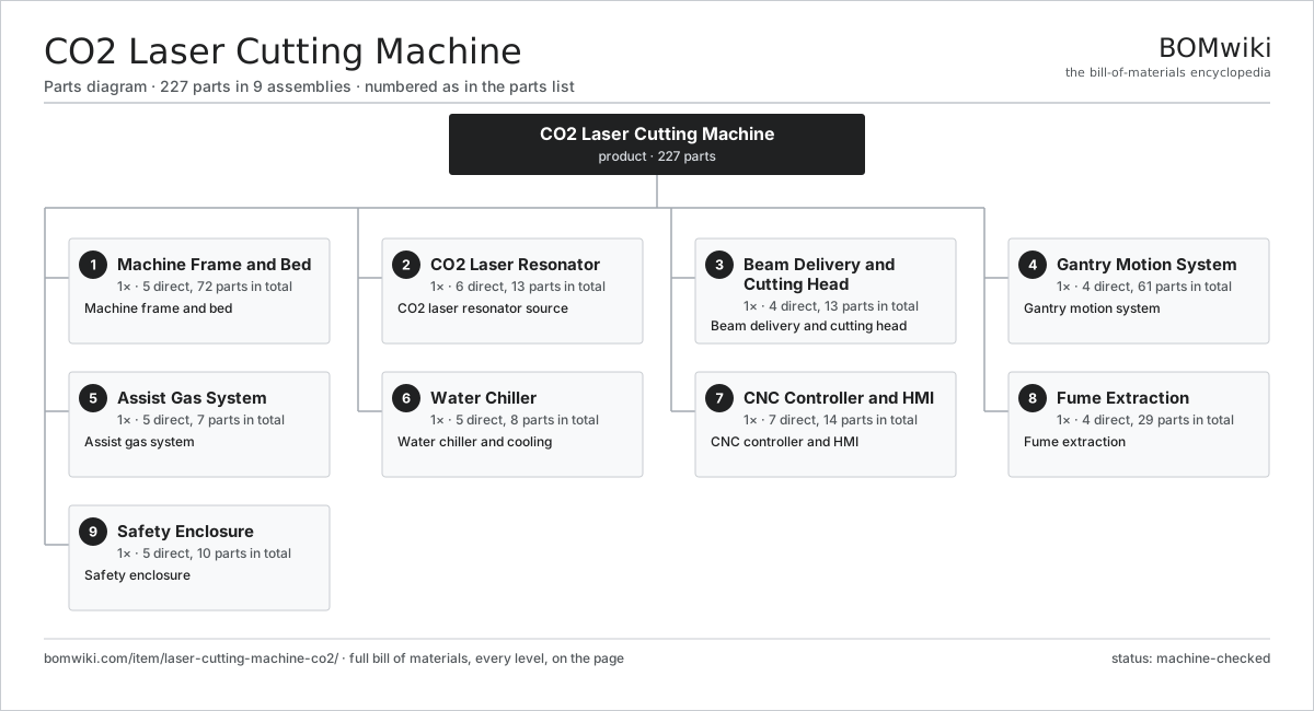
| # | Part | Qty | What it does |
|---|---|---|---|
| 1 | Machine Frame and Bed 5 parts | 1× | Machine frame and bed |
| 2 | CO2 Laser Resonator 6 parts | 1× | CO2 laser resonator source |
| 3 | Beam Delivery and Cutting Head 4 parts | 1× | Beam delivery and cutting head |
| 4 | Gantry Motion System 4 parts | 1× | Gantry motion system |
| 5 | Assist Gas System 5 parts | 1× | Assist gas system |
| 6 | Water Chiller 5 parts | 1× | Water chiller and cooling |
| 7 | CNC Controller and HMI 7 parts | 1× | CNC controller and HMI |
| 8 | Fume Extraction 4 parts | 1× | Fume extraction |
| 9 | Safety Enclosure 5 parts | 1× | Safety enclosure |
3D model
No 3D model yet. Have a CAD file of this? Add a 3D model — STL renders right on this page; STEP, FreeCAD, and OpenSCAD sources are welcome too (openly licensed, like all 3D models on BOMwiki).
Build & assembly graph
expand / collapse · shared sub-assemblies converge · links to related products · est. labourTap an assembly to expand/collapse · tap a part to open it · use “Open page” for any node · drag to pan, scroll to zoom.
Bill of materials for CO2 Laser Cutting Machine
9 top-level lines · 88 rows shown · 227 parts total · indented to 3 levels| # | Item / sub-assembly | Part no. | Qty/assy | Ext. qty | Parts | Type |
|---|---|---|---|---|---|---|
| 1 | Machine Frame and Bed 5 parts | laser-cutting-machine-co2-frame | 1× | 1 | 72 | assembly |
| 1.1 | Base Frame Weldment | laser-cutting-machine-co2-frame-weldment | 1× | 1 | · | part |
| 1.2 | Slat Work Table 3 parts | laser-cutting-machine-co2-slat-bed | 1× | 1 | 62 | assembly |
| 1.2.1 | Bed Slat | laser-cutting-machine-co2-bed-slat | 60× | 60 | · | part |
| 1.2.2 | Slat Carrier Frame | laser-cutting-machine-co2-slat-frame | 1× | 1 | · | part |
| 1.2.3 | Dross Tray | laser-cutting-machine-co2-dross-tray | 1× | 1 | · | part |
| 1.3 | Exhaust Plenum | laser-cutting-machine-co2-exhaust-plenum | 1× | 1 | · | part |
| 1.4 | Leveling Foot | laser-cutting-machine-co2-leveling-foot | 6× | 6 | · | part |
| 1.5 | Fastener Set | fastener-set | 2× | 2 | · | part |
| 2 | CO2 Laser Resonator 6 parts | laser-cutting-machine-co2-resonator | 1× | 1 | 13 | assembly |
| 2.1 | CO2 Gas Tube 3 parts | laser-cutting-machine-co2-laser-tube | 1× | 1 | 3 | assembly |
| 2.1.1 | Discharge Bore | laser-cutting-machine-co2-discharge-bore | 1× | 1 | · | part |
| 2.1.2 | Cooling Jacket | laser-cutting-machine-co2-cooling-jacket | 1× | 1 | · | part |
| 2.1.3 | O-Ring Set | oring-set | 1× | 1 | · | part |
| 2.2 | RF Power Supply 5 parts | laser-cutting-machine-co2-rf-supply | 1× | 1 | 5 | assembly |
| 2.2.1 | RF Amplifier | laser-cutting-machine-co2-rf-amplifier | 1× | 1 | · | part |
| 2.2.2 | Matching Network | laser-cutting-machine-co2-rf-match | 1× | 1 | · | part |
| 2.2.3 | Power Supply | power-supply | 1× | 1 | · | part |
| 2.2.4 | Bare PCB | pcb-bare | 1× | 1 | · | part |
| 2.2.5 | SMD Passive (R/C/L) | smd-passives | 1× | 1 | · | part |
| 2.3 | Laser Gas Mixture | laser-cutting-machine-co2-gas-mix | 1× | 1 | · | part |
| 2.4 | Rear Mirror | laser-cutting-machine-co2-rear-mirror | 1× | 1 | · | part |
| 2.5 | Output Coupler | laser-cutting-machine-co2-output-coupler | 1× | 1 | · | part |
| 2.6 | RF Electrode | laser-cutting-machine-co2-rf-electrode | 2× | 2 | · | part |
| 3 | Beam Delivery and Cutting Head 4 parts | laser-cutting-machine-co2-beam-delivery | 1× | 1 | 13 | assembly |
| 3.1 | Bend Mirror | laser-cutting-machine-co2-bend-mirror | 3× | 3 | · | part |
| 3.2 | Beam Tube and Bellows 2 parts | laser-cutting-machine-co2-beam-tube | 1× | 1 | 4 | assembly |
| 3.2.1 | Beam Tube Section | laser-cutting-machine-co2-tube-section | 2× | 2 | · | part |
| 3.2.2 | Beam Bellows | laser-cutting-machine-co2-bellows | 2× | 2 | · | part |
| 3.3 | Cutting Head 5 parts | laser-cutting-machine-co2-cutting-head | 1× | 1 | 5 | assembly |
| 3.3.1 | Focusing Lens | laser-cutting-machine-co2-focus-lens | 1× | 1 | · | part |
| 3.3.2 | Cutting Nozzle | laser-cutting-machine-co2-nozzle | 1× | 1 | · | part |
| 3.3.3 | Height Sensor | laser-cutting-machine-co2-height-sensor | 1× | 1 | · | part |
| 3.3.4 | Autofocus Motor | laser-cutting-machine-co2-autofocus-motor | 1× | 1 | · | part |
| 3.3.5 | Protective Window | laser-cutting-machine-co2-protective-window | 1× | 1 | · | part |
| 3.4 | Beam Shutter | laser-cutting-machine-co2-beam-shutter | 1× | 1 | · | part |
| 4 | Gantry Motion System 4 parts | laser-cutting-machine-co2-motion | 1× | 1 | 61 | assembly |
| 4.1 | Gantry Bridge | laser-cutting-machine-co2-gantry-bridge | 1× | 1 | · | part |
| 4.2 | X Axis Drive 4 parts | laser-cutting-machine-co2-x-axis | 1× | 1 | 29 | assembly |
| 4.2.1 | Linear Guide Rail | linear-guide | 2× | 2 | · | part |
| 4.2.2 | Ball Screw | ball-screw | 1× | 1 | · | part |
| 4.2.3 | Servo Motor 4 parts + deeper › | servo-motor | 1× | 1 | 24 | assembly |
| 4.2.4 | Ball Bearing | ball-bearing | 2× | 2 | · | part |
| 4.3 | Y Axis Drive 4 parts | laser-cutting-machine-co2-y-axis | 1× | 1 | 29 | assembly |
| 4.3.1 | Linear Guide Rail | linear-guide | 2× | 2 | · | part |
| 4.3.2 | Ball Screw | ball-screw | 1× | 1 | · | part |
| 4.3.3 | Servo Motor 4 parts + deeper › | servo-motor | 1× | 1 | 24 | assembly |
| 4.3.4 | Ball Bearing | ball-bearing | 2× | 2 | · | part |
| 4.4 | Drag Chain | laser-cutting-machine-co2-drag-chain | 2× | 2 | · | part |
| 5 | Assist Gas System 5 parts | laser-cutting-machine-co2-gas-system | 1× | 1 | 7 | assembly |
| 5.1 | Gas Regulator | laser-cutting-machine-co2-gas-regulator | 2× | 2 | · | part |
| 5.2 | Gas Solenoid Valve | laser-cutting-machine-co2-gas-solenoid | 2× | 2 | · | part |
| 5.3 | Proportional Valve | laser-cutting-machine-co2-proportional-valve | 1× | 1 | · | part |
| 5.4 | Pressure Sensor | pressure-sensor | 1× | 1 | · | part |
| 5.5 | Gas Manifold | laser-cutting-machine-co2-gas-manifold | 1× | 1 | · | part |
| 6 | Water Chiller 5 parts | laser-cutting-machine-co2-chiller | 1× | 1 | 8 | assembly |
| 6.1 | Refrigeration Circuit | laser-cutting-machine-co2-refrig-circuit | 1× | 1 | · | part |
| 6.2 | Coolant Pump | laser-cutting-machine-co2-coolant-pump | 1× | 1 | · | part |
| 6.3 | Coolant Tank | laser-cutting-machine-co2-coolant-tank | 1× | 1 | · | part |
| 6.4 | Coolant Line | laser-cutting-machine-co2-coolant-line | 4× | 4 | · | part |
| 6.5 | Flow Switch | laser-cutting-machine-co2-flow-switch | 1× | 1 | · | part |
| 7 | CNC Controller and HMI 7 parts | laser-cutting-machine-co2-cnc | 1× | 1 | 14 | assembly |
| 7.1 | Controller Board 4 parts | laser-cutting-machine-co2-controller-pcb | 1× | 1 | 7 | assembly |
| 7.1.1 | Bare PCB | pcb-bare | 1× | 1 | · | part |
| 7.1.2 | Microcontroller | mcu | 1× | 1 | · | part |
| 7.1.3 | SMD Passive (R/C/L) | smd-passives | 1× | 1 | · | part |
| 7.1.4 | Connector | connector | 4× | 4 | · | part |
| 7.2 | Microcontroller | mcu | 1× | 1 | · | part |
| 7.3 | Servo Drive | laser-cutting-machine-co2-servo-drive | 2× | 2 | · | part |
| 7.4 | I/O Module | laser-cutting-machine-co2-io-module | 1× | 1 | · | part |
| 7.5 | LCD Panel | lcd-panel | 1× | 1 | · | part |
| 7.6 | Power Supply | power-supply | 1× | 1 | · | part |
| 7.7 | Wire Bundle | wire-bundle | 1× | 1 | · | part |
| 8 | Fume Extraction 4 parts | laser-cutting-machine-co2-fume | 1× | 1 | 29 | assembly |
| 8.1 | Extraction Blower 4 parts | laser-cutting-machine-co2-blower | 1× | 1 | 25 | assembly |
| 8.1.1 | Stator Assembly 3 parts + deeper › | stator-assembly | 1× | 1 | 3 | assembly |
| 8.1.2 | Rotor Assembly 4 parts + deeper › | rotor-assembly | 1× | 1 | 19 | assembly |
| 8.1.3 | Fan Impeller | laser-cutting-machine-co2-impeller | 1× | 1 | · | part |
| 8.1.4 | Ball Bearing | ball-bearing | 2× | 2 | · | part |
| 8.2 | Filter Cartridge | laser-cutting-machine-co2-filter-cartridge | 2× | 2 | · | part |
| 8.3 | Ducting | laser-cutting-machine-co2-ducting | 1× | 1 | · | part |
| 8.4 | Relay | relay | 1× | 1 | · | part |
| 9 | Safety Enclosure 5 parts | laser-cutting-machine-co2-enclosure | 1× | 1 | 10 | assembly |
| 9.1 | Enclosure Panels | laser-cutting-machine-co2-enclosure-panel | 1× | 1 | · | part |
| 9.2 | Laser-Safe Window | laser-cutting-machine-co2-safe-window | 2× | 2 | · | part |
| 9.3 | Door Interlock | laser-cutting-machine-co2-door-interlock | 2× | 2 | · | part |
| 9.4 | Emergency Stop | laser-cutting-machine-co2-estop | 1× | 1 | · | part |
| 9.5 | Sheet Metal Panel | sheet-panel | 4× | 4 | · | part |
Related products
same domain, ranked by shared parts Crankshaft Grinder
511 parts · shares 6 with this page
Crankshaft Grinder
511 parts · shares 6 with this page
 Creep-Feed Grinder
571 parts · shares 6 with this page
Cut-to-Length Line
500 parts · shares 6 with this page
Creep-Feed Grinder
571 parts · shares 6 with this page
Cut-to-Length Line
500 parts · shares 6 with this page
Sourcing: possible vendors
Prices, MOQ, and lead times are algorithmic estimates, not quotes, and not claims about these companies. Company mappings are curated by keyword; est. price band $10k–$1M. How estimates work| Vendor | HQ | Specialty | MOQ | Lead time |
|---|---|---|---|---|
|
🇩🇪DMG MORI
dmgmori.com ↗
|
Bielefeld, DE | Machine tools | 5 units | 12–20 wks |
|
🇯🇵Mazak
mazak.com ↗
|
Oguchi, JP | Machine tools | 5 units | 12–20 wks |
| haascnc.com ↗ | Oxnard, US | CNC machine tools | 5 units | 12–20 wks |
|
🇯🇵Okuma
okuma.com ↗
|
Niwa, JP | Machine tools | 5 units | 12–20 wks |
|
🇩🇪Trumpf
trumpf.com ↗
|
Ditzingen, DE | Laser & sheet-metal machines | 5 units | 12–20 wks |
1,240-word article