Shear Forming Machine
ProductOverview
A shear forming machine, also called a power spinning machine, forms a flat circular sheet into a cone or dished shape while deliberately thinning the wall. Unlike conventional spinning, where metal is bent over a mandrel and keeps roughly its original thickness, shear forming holds a fixed gap between the roller and the mandrel so the metal is sheared down to a smaller, precisely controlled thickness as it is pushed into shape. The wall slides axially under the roller while the diameter at any point stays the same, which is why it is called shear forming.
The machine is organized around a Machine Bed carrying a rotating Headstock, one or two Roller Arm slides, and a hydraulic Tailstock that clamps the blank. A Hydraulic Power Pack supplies clamp pressure, the CNC Control drives the roller path, and the Coolant System cools the contact zone. The work area is enclosed by the Guarding.
How it works
A flat blank is loaded against the Faceplate at the base of the Conical Mandrel and held in place by the Clamp Pad, which the Clamp Cylinder presses on with several hundred kilonewtons. The Spindle Motor spins the Main Spindle, mandrel, blank, and clamp pad together as one unit.
With the blank turning, the Roller Arm feeds its Forming Roller in to set the gap and then sweeps it from the center toward the rim along the cone surface. The metal in front of the roller has nowhere to go but along the mandrel, so it flows toward the rim and the wall thins. The final wall thickness follows the sine law: it equals the starting blank thickness multiplied by the sine of the half-angle of the cone. A shallow cone thins a lot, a steep cone thins little, and that geometric relationship is what makes the finished thickness predictable from the blank and the mandrel angle alone.
The Radial Slide sets the gap that fixes thickness and the Axial Slide controls the sweep, both driven by a Ball Screw and Servo Motor running on Linear Guide Rail rails. On a two-roller machine the second arm follows the first to balance the radial load on the mandrel and improve the surface. A Forming Load Cell on each arm reports forming force so the control can hold it within limits.
Subsystems
The Headstock supplies torque rather than speed. Its Main Spindle runs on preloaded Ball Bearing sets and is driven through a Gearbox Housing with Helical Gear Pair reduction, because the roller load on the mandrel is large. The Conical Mandrel is the master tool, hardened and ground to the exact internal cone the part needs; its surface is reproduced on the inside of every part. Mandrels are interchangeable so one machine can run a family of cone angles.
Each Roller Arm is a precision two-axis slide. Because the wall thickness is set purely by the roller-to-mandrel gap, the slide must hold that gap to a few hundredths of a millimetre over the whole sweep, even as the side load tries to push the arm back. The arm structure and its bearings are sized for stiffness more than speed.
The Hydraulic Power Pack is dedicated to clamping. Its Hydraulic Pump holds pressure and the Valve Manifold meters the clamp cylinder, with Pressure Sensor feedback confirming the blank is seated before the roller engages. If the blank loosens during forming it can wrinkle or tear, so clamp force is monitored throughout the cycle.
Control and sensing
The CNC Control runs the spindle plus the radial and axial axes for each arm, typically five axes in total. A CNC Unit computes the roller path so the gap stays constant as the contact point moves up the cone, and one Servo Drive per axis closes its loop. The operator works through an LCD Panel. Forming force from the arm load cells is fed back so the control can ease the sweep rate if the force climbs, which protects both the tool and the part from tearing. Field signals run over a Wire Bundle and Connector set, with Relay outputs for clamping and the larger interlocked loads.
Materials and tooling
Shear forming suits ductile metals that thin without cracking: low-carbon and stainless steels, aluminium alloys, and titanium. The blank is a flat disc, often laser or plasma cut to size, and the process is usually a single pass because the sine law sets thickness directly rather than through repeated reductions. The Forming Roller is the wear part, made from D2 or similar tool steel and polished so the burnished finish transfers to the part. The Coolant System floods the contact through aimed Coolant Nozzle jets to control heat and protect the roller. The resulting surface is smooth enough that many parts need no further finishing.
Variants and use
Machines range from small benchtop units forming lighting reflectors and cookware to large machines producing rocket nose cones, missile bodies, pressure-vessel heads, and large dished ends. Some machines combine shear forming and flow forming so a single setup can both form a cone and thin a straight section. Vertical configurations are common for very large dished heads, while horizontal machines suit longer conical parts. The strengths of the process are a precise, predictable wall thickness, a work-hardened and therefore stronger wall, a fine burnished surface, and almost no scrap, which is why it is used heavily in aerospace, defence, and process-equipment manufacturing.
Shear Forming Machine parts and their functions
8 top-level parts · 201 parts in total · full bill of materials below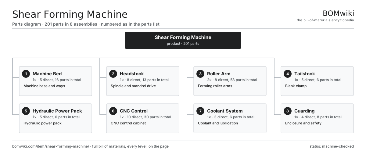
| # | Part | Qty | What it does |
|---|---|---|---|
| 1 | Machine Bed 5 parts | 1× | Machine base and ways |
| 2 | Headstock 8 parts | 1× | Spindle and mandrel drive |
| 3 | Roller Arm 8 parts | 2× | Forming roller arms |
| 4 | Tailstock 5 parts | 1× | Blank clamp |
| 5 | Hydraulic Power Pack 5 parts | 1× | Hydraulic power pack |
| 6 | CNC Control 10 parts | 1× | CNC control cabinet |
| 7 | Coolant System 3 parts | 1× | Coolant and lubrication |
| 8 | Guarding 4 parts | 1× | Enclosure and safety |
3D model
No 3D model yet. Have a CAD file of this? Add a 3D model — STL renders right on this page; STEP, FreeCAD, and OpenSCAD sources are welcome too (openly licensed, like all 3D models on BOMwiki).
Build & assembly graph
expand / collapse · shared sub-assemblies converge · links to related products · est. labourTap an assembly to expand/collapse · tap a part to open it · use “Open page” for any node · drag to pan, scroll to zoom.
Bill of materials for Shear Forming Machine
8 top-level lines · 60 rows shown · 201 parts total · indented to 3 levels| # | Item / sub-assembly | Part no. | Qty/assy | Ext. qty | Parts | Type |
|---|---|---|---|---|---|---|
| 1 | Machine Bed 5 parts | shear-forming-machine-bed | 1× | 1 | 16 | assembly |
| 1.1 | Base Casting | shear-forming-machine-base-casting | 1× | 1 | · | part |
| 1.2 | Linear Guide Rail | linear-guide | 4× | 4 | · | part |
| 1.3 | Way Cover | shear-forming-machine-way-cover | 4× | 4 | · | part |
| 1.4 | Leveling Pad | shear-forming-machine-leveling-pad | 6× | 6 | · | part |
| 1.5 | Fastener Set | fastener-set | 1× | 1 | · | part |
| 2 | Headstock 8 parts | shear-forming-machine-headstock | 1× | 1 | 13 | assembly |
| 2.1 | Main Spindle | shear-forming-machine-spindle | 1× | 1 | · | part |
| 2.2 | Spindle Motor | shear-forming-machine-spindle-motor | 1× | 1 | · | part |
| 2.3 | Gearbox Housing | gearbox-housing | 1× | 1 | · | part |
| 2.4 | Helical Gear Pair | gear-pair | 2× | 2 | · | part |
| 2.5 | Conical Mandrel | shear-forming-machine-mandrel | 1× | 1 | · | part |
| 2.6 | Faceplate | shear-forming-machine-faceplate | 1× | 1 | · | part |
| 2.7 | Ball Bearing | ball-bearing | 4× | 4 | · | part |
| 2.8 | Oil Seal | oil-seal | 2× | 2 | · | part |
| 3 | Roller Arm 8 parts | shear-forming-machine-roller-arm | 2× | 2 | 58 | assembly |
| 3.1 | Forming Roller | shear-forming-machine-forming-roller | 1× | 2 | · | part |
| 3.2 | Roller Spindle | shear-forming-machine-roller-spindle | 1× | 2 | · | part |
| 3.3 | Radial Slide | shear-forming-machine-radial-slide | 1× | 2 | · | part |
| 3.4 | Axial Slide | shear-forming-machine-axial-slide | 1× | 2 | · | part |
| 3.5 | Ball Screw | ball-screw | 2× | 4 | · | part |
| 3.6 | Servo Motor 4 parts | servo-motor | 2× | 4 | 24 | assembly |
| 3.6.1 | Stator Assembly 3 parts + deeper › | stator-assembly | 1× | 4 | 3 | assembly |
| 3.6.2 | Rotor Assembly 4 parts + deeper › | rotor-assembly | 1× | 4 | 19 | assembly |
| 3.6.3 | Encoder | encoder | 1× | 4 | · | part |
| 3.6.4 | Motor Housing | motor-housing | 1× | 4 | · | part |
| 3.7 | Forming Load Cell | shear-forming-machine-load-cell | 1× | 2 | · | part |
| 3.8 | Ball Bearing | ball-bearing | 3× | 6 | · | part |
| 4 | Tailstock 5 parts | shear-forming-machine-tailstock | 1× | 1 | 6 | assembly |
| 4.1 | Tailstock Body | shear-forming-machine-tailstock-body | 1× | 1 | · | part |
| 4.2 | Clamp Cylinder | shear-forming-machine-clamp-cylinder | 1× | 1 | · | part |
| 4.3 | Clamp Pad | shear-forming-machine-clamp-pad | 1× | 1 | · | part |
| 4.4 | Ball Bearing | ball-bearing | 2× | 2 | · | part |
| 4.5 | O-Ring Set | oring-set | 1× | 1 | · | part |
| 5 | Hydraulic Power Pack 5 parts | shear-forming-machine-hydraulic-unit | 1× | 1 | 6 | assembly |
| 5.1 | Hydraulic Pump | shear-forming-machine-hydraulic-pump | 1× | 1 | · | part |
| 5.2 | Hydraulic Tank | shear-forming-machine-hydraulic-tank | 1× | 1 | · | part |
| 5.3 | Valve Manifold | shear-forming-machine-valve-block | 1× | 1 | · | part |
| 5.4 | Pressure Sensor | pressure-sensor | 2× | 2 | · | part |
| 5.5 | O-Ring Set | oring-set | 1× | 1 | · | part |
| 6 | CNC Control 10 parts | shear-forming-machine-cnc-control | 1× | 1 | 30 | assembly |
| 6.1 | CNC Unit | shear-forming-machine-cnc-unit | 1× | 1 | · | part |
| 6.2 | Servo Drive | shear-forming-machine-servo-drive | 5× | 5 | · | part |
| 6.3 | LCD Panel | lcd-panel | 1× | 1 | · | part |
| 6.4 | Power Supply | power-supply | 1× | 1 | · | part |
| 6.5 | Bare PCB | pcb-bare | 1× | 1 | · | part |
| 6.6 | Microcontroller | mcu | 1× | 1 | · | part |
| 6.7 | SMD Passive (R/C/L) | smd-passives | 1× | 1 | · | part |
| 6.8 | Relay | relay | 6× | 6 | · | part |
| 6.9 | Wire Bundle | wire-bundle | 1× | 1 | · | part |
| 6.10 | Connector | connector | 12× | 12 | · | part |
| 7 | Coolant System 3 parts | shear-forming-machine-coolant-system | 1× | 1 | 6 | assembly |
| 7.1 | Coolant Pump | shear-forming-machine-coolant-pump | 1× | 1 | · | part |
| 7.2 | Coolant Tank | shear-forming-machine-coolant-tank | 1× | 1 | · | part |
| 7.3 | Coolant Nozzle | shear-forming-machine-coolant-nozzle | 4× | 4 | · | part |
| 8 | Guarding 4 parts | shear-forming-machine-guard | 1× | 1 | 8 | assembly |
| 8.1 | Sheet Metal Panel | sheet-panel | 5× | 5 | · | part |
| 8.2 | Access Door | shear-forming-machine-access-door | 1× | 1 | · | part |
| 8.3 | Viewing Window | shear-forming-machine-window | 1× | 1 | · | part |
| 8.4 | Door Interlock | shear-forming-machine-door-interlock | 1× | 1 | · | part |
Related products
same domain, ranked by shared parts Creep-Feed Grinder
571 parts · shares 8 with this page
Cut-to-Length Line
500 parts · shares 8 with this page
Drag Finishing Machine
735 parts · shares 8 with this page
Creep-Feed Grinder
571 parts · shares 8 with this page
Cut-to-Length Line
500 parts · shares 8 with this page
Drag Finishing Machine
735 parts · shares 8 with this page
 Flow Forming Machine
272 parts · shares 8 with this page
Mandrel Tube Bender
116 parts · shares 8 with this page
Flow Forming Machine
272 parts · shares 8 with this page
Mandrel Tube Bender
116 parts · shares 8 with this page
Sourcing: possible vendors
Prices, MOQ, and lead times are algorithmic estimates, not quotes, and not claims about these companies. Company mappings are curated by keyword; est. price band $10k–$1M. How estimates work| Vendor | HQ | Specialty | MOQ | Lead time |
|---|---|---|---|---|
|
🇩🇪DMG MORI
dmgmori.com ↗
|
Bielefeld, DE | Machine tools | 5 units | 12–20 wks |
|
🇯🇵Mazak
mazak.com ↗
|
Oguchi, JP | Machine tools | 5 units | 12–20 wks |
| haascnc.com ↗ | Oxnard, US | CNC machine tools | 5 units | 12–20 wks |
|
🇯🇵Okuma
okuma.com ↗
|
Niwa, JP | Machine tools | 5 units | 12–20 wks |
|
🇩🇪Trumpf
trumpf.com ↗
|
Ditzingen, DE | Laser & sheet-metal machines | 5 units | 12–20 wks |
996-word article