Hydroforming Press
ProductOverview
Hydroforming shapes metal with pressurised fluid instead of a solid punch. A blank or tube is placed in a closed die and forming fluid is pumped into it at extreme pressure, often 1,000 to 4,000 bar, pushing the metal outward until it presses against the die cavity and takes its shape. Because the pressure acts evenly over the whole surface, the process makes smooth, stiff, single-piece parts with complex curves and few welds: automotive engine cradles, exhaust manifolds, radiator supports, bicycle frame tubes, and large appliance panels. The cost is a very large machine, because that internal pressure also tries violently to push the die open.
A Hydroforming Press is built to generate and contain that pressure. A high-tonnage Clamp Frame and a Die Clamping System hold the Forming Die Set shut, a Pressure Intensifier Unit makes the high pressure, a Forming Fluid System supplies and seals the forming fluid, and for tube work an Axial Feed System pushes material into the part as it expands. A Hydraulic Unit powers the clamp and feed, and everything is coordinated by a CNC Control System behind a pressure-rated Safety System.
Frame and Clamp Force
The defining structural problem is the die-opening force. Forming pressure acting on the projected area of the part can reach several thousand tons, and the frame must hold the die parting line closed against all of it or the part will flash and the die will be damaged. The Clamp Frame is therefore very heavy: a stack of pinned Frame Plate (or a wire-wound design) pulled together by pre-tensioned Frame Tie Rod members, with ground Platen surfaces seating the die. On top of the frame, the Die Clamping System uses several large Clamp Cylinder units driving Clamp Piston members to close and hold the die. A Clamp Position Sensor confirms full closure before any forming pressure is admitted, since pressurising a partly open die is dangerous.
Generating the Pressure
Pump systems top out around 300 bar, far below forming pressure, so the press uses a pressure Pressure Intensifier Unit. A large-area Intensifier Drive Cylinder driven by pump oil pushes a small-diameter Intensifier Plunger into the forming fluid; the ratio of the two areas multiplies the pressure, so 280 bar of pump oil can become 2,000 to 4,000 bar of forming pressure. A High-Pressure Check Valve pair isolates the intensifier so it can re-stroke and build pressure in steps, and a High-Pressure Relief Valve protects the high-pressure circuit and the die from over-pressure.
Die and Fluid
The part shape lives in the Forming Die Set: an Upper Die Half and Lower Die Half half whose cavity is the finished geometry, with replaceable Die Insert pieces at the high-wear radii and Die Guide Pin members keeping the parting line aligned. The Forming Fluid System manages the medium itself. A Fill Pump floods the cavity or tube with a water-oil emulsion from the Fluid Tank, a Fluid Filter keeps metal fines out of the seals and intensifier, and an High-Pressure Seal at the workpiece interface holds full forming pressure without leaking.
Axial Feed for Tube Forming
Tube hydroforming has a particular failure mode: as the tube bulges outward to fill the die, its wall thins, and if nothing feeds in more material it will burst. The Axial Feed System solves this. An Axial Feed Cylinder at each end drives a Sealing Feed Punch that seals the tube end, admits forming fluid, and at the same time pushes material axially inward to feed the expanding bulge so the wall stays thick. An Counter Punch can apply back-pressure to control how far a protrusion forms and to prevent bursting. The skill of tube hydroforming is feeding material in step with the rising pressure, which is exactly what the control system profiles.
Hydraulics, Control and Safety
The Hydraulic Unit supplies pump oil to the clamp cylinders, the intensifier drive and the axial feed, each metered by its own Proportional Valve, from a Main Pump driven by a 55 to 160 kW Pump Motor. The Control System runs on a CNC Controller that executes the forming curve, the relationship between internal pressure and axial feed over time, that determines whether the part forms cleanly or splits. The operator sets up the curve and watches it on the HMI Panel. Because high-pressure fluid stores a great deal of energy, the Safety System is built around a Pressure Guard enclosure sized to contain a burst, Interlock Switch guard locks that prevent access while pressurised, and a monitored Safety Relay.
Variants and Use
Two main families exist. Sheet hydroforming presses a flat blank against a one-sided die using fluid pressure (or a flexible diaphragm holding the fluid), giving smooth panels with deep draws and no tool marks on the show side. Tube hydroforming, the more common industrial use, expands a tube inside a closed die with axial feed, producing hollow structural parts that replace several stamped-and-welded pieces with one stiff, lightweight component. Clamp forces run from about 1,000 tons for small parts to 10,000 tons for large automotive structures. Compared with a Deep Drawing Press, which forms with a solid punch and a blank holder, hydroforming uses pressure as the punch, which spreads the load evenly and allows shapes that a rigid tool cannot reach. The trade-offs are slower cycles and a much larger, more expensive machine.
Hydroforming Press parts and their functions
9 top-level parts · 330 parts in total · full bill of materials below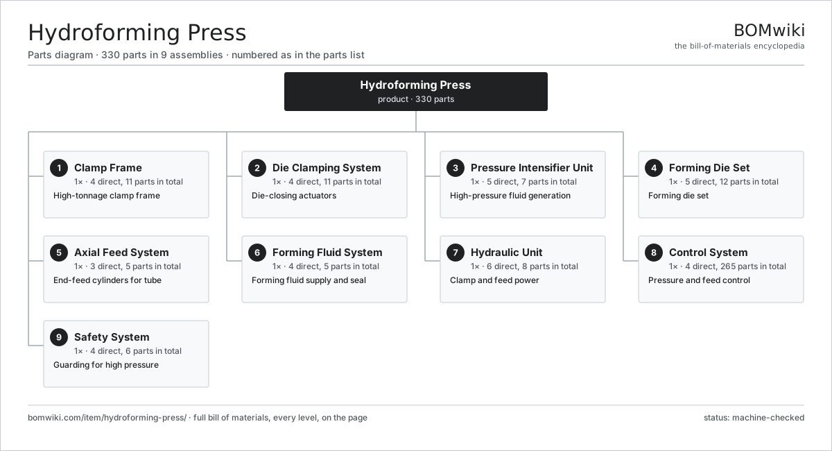
| # | Part | Qty | What it does |
|---|---|---|---|
| 1 | Clamp Frame 4 parts | 1× | High-tonnage clamp frame |
| 2 | Die Clamping System 4 parts | 1× | Die-closing actuators |
| 3 | Pressure Intensifier Unit 5 parts | 1× | High-pressure fluid generation |
| 4 | Forming Die Set 5 parts | 1× | Forming die set |
| 5 | Axial Feed System 3 parts | 1× | End-feed cylinders for tube |
| 6 | Forming Fluid System 4 parts | 1× | Forming fluid supply and seal |
| 7 | Hydraulic Unit 6 parts | 1× | Clamp and feed power |
| 8 | Control System 4 parts | 1× | Pressure and feed control |
| 9 | Safety System 4 parts | 1× | Guarding for high pressure |
3D model
No 3D model yet. Have a CAD file of this? Add a 3D model — STL renders right on this page; STEP, FreeCAD, and OpenSCAD sources are welcome too (openly licensed, like all 3D models on BOMwiki).
Build & assembly graph
expand / collapse · shared sub-assemblies converge · links to related products · est. labourTap an assembly to expand/collapse · tap a part to open it · use “Open page” for any node · drag to pan, scroll to zoom.
Bill of materials for Hydroforming Press
9 top-level lines · 57 rows shown · 330 parts total · indented to 3 levels| # | Item / sub-assembly | Part no. | Qty/assy | Ext. qty | Parts | Type |
|---|---|---|---|---|---|---|
| 1 | Clamp Frame 4 parts | hfp-frame | 1× | 1 | 11 | assembly |
| 1.1 | Frame Plate | hfp-frame-plates | 4× | 4 | · | part |
| 1.2 | Frame Tie Rod | hfp-tie-rod | 4× | 4 | · | part |
| 1.3 | Platen | hfp-platen | 2× | 2 | · | part |
| 1.4 | Fastener Set | fastener-set | 1× | 1 | · | part |
| 2 | Die Clamping System 4 parts | hfp-clamping-system | 1× | 1 | 11 | assembly |
| 2.1 | Clamp Cylinder | hfp-clamp-cylinder | 4× | 4 | · | part |
| 2.2 | Clamp Piston | hfp-clamp-piston | 4× | 4 | · | part |
| 2.3 | Clamp Seal Kit | hfp-clamp-seal-kit | 1× | 1 | · | part |
| 2.4 | Clamp Position Sensor | hfp-clamp-position-sensor | 2× | 2 | · | part |
| 3 | Pressure Intensifier Unit 5 parts | hfp-intensifier-unit | 1× | 1 | 7 | assembly |
| 3.1 | Intensifier Drive Cylinder | hfp-intensifier-cylinder | 1× | 1 | · | part |
| 3.2 | Intensifier Plunger | hfp-intensifier-plunger | 1× | 1 | · | part |
| 3.3 | High-Pressure Check Valve | hfp-hp-check-valve | 2× | 2 | · | part |
| 3.4 | High-Pressure Relief Valve | hfp-hp-relief-valve | 1× | 1 | · | part |
| 3.5 | Pressure Sensor | pressure-sensor | 2× | 2 | · | part |
| 4 | Forming Die Set 5 parts | hfp-forming-die | 1× | 1 | 12 | assembly |
| 4.1 | Upper Die Half | hfp-die-upper | 1× | 1 | · | part |
| 4.2 | Lower Die Half | hfp-die-lower | 1× | 1 | · | part |
| 4.3 | Die Insert | hfp-die-insert | 2× | 2 | · | part |
| 4.4 | Die Guide Pin | hfp-die-guide-pin | 4× | 4 | · | part |
| 4.5 | Ball Bearing | ball-bearing | 4× | 4 | · | part |
| 5 | Axial Feed System 3 parts | hfp-axial-feed-system | 1× | 1 | 5 | assembly |
| 5.1 | Axial Feed Cylinder | hfp-axial-cylinder | 2× | 2 | · | part |
| 5.2 | Sealing Feed Punch | hfp-feed-punch | 2× | 2 | · | part |
| 5.3 | Counter Punch | hfp-counter-punch | 1× | 1 | · | part |
| 6 | Forming Fluid System 4 parts | hfp-fluid-system | 1× | 1 | 5 | assembly |
| 6.1 | Fill Pump | hfp-fill-pump | 1× | 1 | · | part |
| 6.2 | Fluid Tank | hfp-fluid-tank | 1× | 1 | · | part |
| 6.3 | Fluid Filter | hfp-fluid-filter | 1× | 1 | · | part |
| 6.4 | High-Pressure Seal | hfp-hp-seal | 2× | 2 | · | part |
| 7 | Hydraulic Unit 6 parts | hfp-hydraulic-unit | 1× | 1 | 8 | assembly |
| 7.1 | Main Pump | hfp-pump | 1× | 1 | · | part |
| 7.2 | Pump Motor | hfp-pump-motor | 1× | 1 | · | part |
| 7.3 | Oil Reservoir | hfp-reservoir | 1× | 1 | · | part |
| 7.4 | Proportional Valve | hfp-proportional-valve | 3× | 3 | · | part |
| 7.5 | Return Line Filter | return-filter | 1× | 1 | · | part |
| 7.6 | Oil Cooler | hfp-cooler | 1× | 1 | · | part |
| 8 | Control System 4 parts | hfp-control-system | 1× | 1 | 265 | assembly |
| 8.1 | CNC Controller 4 parts | hfp-cnc-controller | 1× | 1 | 169 | assembly |
| 8.1.1 | Bare PCB | pcb-bare | 1× | 1 | · | part |
| 8.1.2 | Microcontroller | mcu | 2× | 2 | · | part |
| 8.1.3 | Relay | relay | 6× | 6 | · | part |
| 8.1.4 | SMD Passive (R/C/L) | smd-passives | 160× | 160 | · | part |
| 8.2 | HMI Panel 5 parts | hfp-hmi | 1× | 1 | 94 | assembly |
| 8.2.1 | LCD Panel | lcd-panel | 1× | 1 | · | part |
| 8.2.2 | Touch Digitizer | touch-digitizer | 1× | 1 | · | part |
| 8.2.3 | Bare PCB | pcb-bare | 1× | 1 | · | part |
| 8.2.4 | Microcontroller | mcu | 1× | 1 | · | part |
| 8.2.5 | SMD Passive (R/C/L) | smd-passives | 90× | 90 | · | part |
| 8.3 | Power Supply | power-supply | 1× | 1 | · | part |
| 8.4 | Wire Bundle | wire-bundle | 1× | 1 | · | part |
| 9 | Safety System 4 parts | hfp-safety-system | 1× | 1 | 6 | assembly |
| 9.1 | Pressure Guard | hfp-pressure-guard | 1× | 1 | · | part |
| 9.2 | Interlock Switch | hfp-interlock-switch | 2× | 2 | · | part |
| 9.3 | E-Stop | hfp-estop | 2× | 2 | · | part |
| 9.4 | Safety Relay | hfp-safety-relay | 1× | 1 | · | part |
Related products
same domain, ranked by shared parts Abrasive Flow Machining Machine
279 parts · shares 2 with this page
Bar Chamfering Machine
1,148 parts · shares 2 with this page
Centering and Facing Machine
1,419 parts · shares 2 with this page
CNC Metal Spinning Machine
768 parts · shares 2 with this page
Abrasive Flow Machining Machine
279 parts · shares 2 with this page
Bar Chamfering Machine
1,148 parts · shares 2 with this page
Centering and Facing Machine
1,419 parts · shares 2 with this page
CNC Metal Spinning Machine
768 parts · shares 2 with this page
 CNC Router
899 parts · shares 2 with this page
CNC Router
899 parts · shares 2 with this page
Sourcing: possible vendors
Prices, MOQ, and lead times are algorithmic estimates, not quotes, and not claims about these companies. Company mappings are curated by keyword; est. price band $10k–$1M. How estimates work| Vendor | HQ | Specialty | MOQ | Lead time |
|---|---|---|---|---|
|
🇩🇪DMG MORI
dmgmori.com ↗
|
Bielefeld, DE | Machine tools | 5 units | 12–20 wks |
|
🇯🇵Mazak
mazak.com ↗
|
Oguchi, JP | Machine tools | 5 units | 12–20 wks |
| haascnc.com ↗ | Oxnard, US | CNC machine tools | 5 units | 12–20 wks |
|
🇯🇵Okuma
okuma.com ↗
|
Niwa, JP | Machine tools | 5 units | 12–20 wks |
|
🇩🇪Trumpf
trumpf.com ↗
|
Ditzingen, DE | Laser & sheet-metal machines | 5 units | 12–20 wks |
944-word article