Chain Link Welding Machine
ProductOverview
A chain link welding machine turns a coil of steel wire into a continuous run of welded link chain. Each link is cut from the wire, bent around a former so that it threads through the previous link, and then resistance-welded shut at the butt joint. The result is a closed-link chain in which every link is a solid forged ring, far stronger than the twisted or riveted chain it replaced. The machine does all of this in one repeating cycle driven from a single shaft, so links leave the welder already joined into a chain ready to be coiled, proof-tested, and shipped.
The work flows through five stations in order. The Wire Feed Unit straightens the wire and meters one link length, the Bending Head cuts and forms that length into an open link, the Weld Head clamps and welds the butt joint using power from the Welding Transformer, and the Flash Trimmer shears off the weld upset. The Main Drive times every motion, the Control System sets the weld parameters, and the Electrode Cooling keeps the electrodes from overheating.
Wire handling and forming
Welded chain depends on clean, straight, accurately measured wire. The Powered Decoiler pays wire off the coil under steady tension held by the Dancer Arm, and the Roller Straightener runs it through nine offset Straightening Roller rollers that bend the curl out in both planes. The Feed Roll then push a precise length forward, metered by the cam-driven Feed Servo Cam so each link is the same size.
In the Bending Head the Cutoff Die crops the wire, then the Bending Finger wrap it around the Bending Mandrel, threading the new wire through the link made on the cycle before so the chain stays continuous. The Cam Follower drive these strokes and the Link Gripper then holds the open link with its two butt ends pressed together, presenting the joint to the weld head.
Resistance welding the joint
The weld is a resistance butt weld, a process that needs very high current at very low voltage. The Welding Transformer supplies it: a laminated Transformer Core couples a many-turn Primary Winding to a single-turn Secondary Winding, stepping line voltage down to a few volts at tens of thousands of amps. The SCR Contactor phase-controls the primary so the weld controller can set energy precisely.
At the joint, two Weld Electrode tips of CuCrZr alloy held in water-cooled Electrode Holder units clamp each leg of the link through the Weld Clamp jaws. Current flows across the butt, the contact resistance heats the ends to forging temperature, and the Upset Cylinder forces them together so the metal forges into one piece. A Pressure Sensor watches the upset force, since both current and force decide whether the weld is sound. The heavy Secondary Busbar secondary carries the current with minimal loss.
Flash trimming and drive
A butt weld squeezes a ring of upset metal, the flash, out of the joint. The Flash Trimmer removes it: the Trim Cylinder drives two profiled Trim Die shears across the still-hot weld, paring the flash flush so the finished link is smooth, and the Scrap Chute carries the trimmings away.
Every motion is timed from one Master Camshaft turning inside the Main Drive. The Cam Pack on that shaft drives feed, cut, bend, clamp, upset, and trim in fixed sequence, so the machine cannot weld before the link is formed or trim before it is welded. The Servo Motor and reduction Helical Gear Pair set the cycle rate, and finished chain winds onto the Take-up Reel.
Materials and construction
Chain wire is low to medium carbon steel, or alloy steel for higher grades, chosen so the weld and parent metal harden compatibly. Electrodes are CuCrZr because it holds hardness and conductivity hot; they wear and are dressed or replaced on a schedule. The Base Weldment is a heavy steel structure because welding forces and the upset stroke would shake a light frame out of alignment. Forming tools, the Bending Mandrel and Cutoff Die, are tool steel that wears against the wire and is changed for each link size. The whole spark and pinch zone is wrapped in interlocked Sheet Metal Panel guards.
Variants and use
Machines are built around a wire-size range, so a small welder might make 3-6 mm decorative or load-binding chain while a heavy one makes 13-16 mm lifting and anchor chain. Output chain follows standards such as DIN 5685 short and long link or DIN 763, and lifting grades go on to heat treatment and proof testing after welding. Higher grades use alloy wire and tighter weld control through the Weld Controller, which logs current, time, and force per link. The welded link chain these machines make is used for lifting slings, conveyor and drag chain, anchor and mooring chain, fencing, and traction chain, wherever a closed forged link is needed rather than the open links a manual chain shop could make.
Control and cooling
The Control System ties the stations together. A PLC runs the sequence and interlocks while the Weld Controller fires the SCR Contactor and regulates weld energy from feedback through a Current Sensor. Operators set link size, current, weld time, and upset force at the LCD Panel. Because tens of thousands of amps pass through the electrodes at a high cycle rate, the Electrode Cooling system runs continuously: the Coolant Pump circulates water through the holders and busbars, and the Heat Exchanger dumps the absorbed heat so the electrodes stay within their working temperature and weld quality holds steady through a long production run.
Chain Link Welding Machine parts and their functions
9 top-level parts · 440 parts in total · full bill of materials below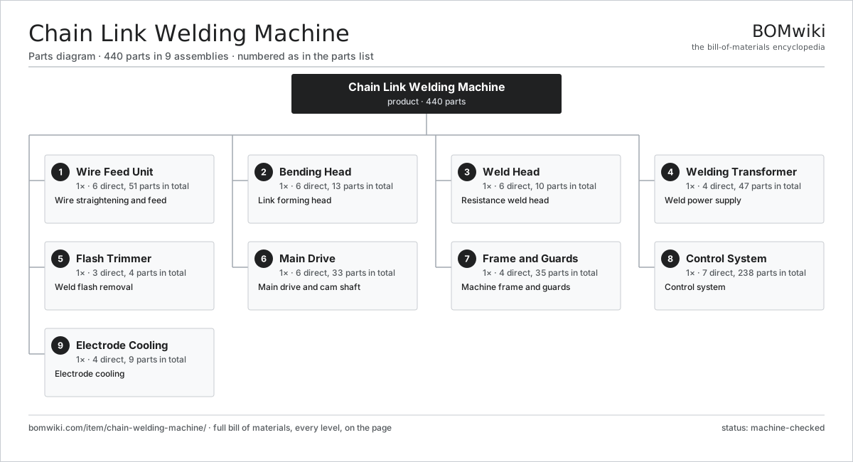
| # | Part | Qty | What it does |
|---|---|---|---|
| 1 | Wire Feed Unit 6 parts | 1× | Wire straightening and feed |
| 2 | Bending Head 6 parts | 1× | Link forming head |
| 3 | Weld Head 6 parts | 1× | Resistance weld head |
| 4 | Welding Transformer 4 parts | 1× | Weld power supply |
| 5 | Flash Trimmer 3 parts | 1× | Weld flash removal |
| 6 | Main Drive 6 parts | 1× | Main drive and cam shaft |
| 7 | Frame and Guards 4 parts | 1× | Machine frame and guards |
| 8 | Control System 7 parts | 1× | Control system |
| 9 | Electrode Cooling 4 parts | 1× | Electrode cooling |
3D model
No 3D model yet. Have a CAD file of this? Add a 3D model — STL renders right on this page; STEP, FreeCAD, and OpenSCAD sources are welcome too (openly licensed, like all 3D models on BOMwiki).
Build & assembly graph
expand / collapse · shared sub-assemblies converge · links to related products · est. labourTap an assembly to expand/collapse · tap a part to open it · use “Open page” for any node · drag to pan, scroll to zoom.
Bill of materials for Chain Link Welding Machine
9 top-level lines · 83 rows shown · 440 parts total · indented to 3 levels| # | Item / sub-assembly | Part no. | Qty/assy | Ext. qty | Parts | Type |
|---|---|---|---|---|---|---|
| 1 | Wire Feed Unit 6 parts | chain-welding-machine-wire-feed | 1× | 1 | 51 | assembly |
| 1.1 | Powered Decoiler 3 parts | chain-welding-machine-decoiler | 1× | 1 | 4 | assembly |
| 1.1.1 | Reel Cradle | chain-welding-machine-reel-cradle | 1× | 1 | · | part |
| 1.1.2 | Dancer Arm | chain-welding-machine-dancer-arm | 1× | 1 | · | part |
| 1.1.3 | Ball Bearing | ball-bearing | 2× | 2 | · | part |
| 1.2 | Roller Straightener 3 parts | chain-welding-machine-straightener | 1× | 1 | 19 | assembly |
| 1.2.1 | Straightening Roller | chain-welding-machine-straightener-roll | 9× | 9 | · | part |
| 1.2.2 | Roller Block | chain-welding-machine-roll-block | 1× | 1 | · | part |
| 1.2.3 | Ball Bearing | ball-bearing | 9× | 9 | · | part |
| 1.3 | Feed Roll | chain-welding-machine-feed-rolls | 2× | 2 | · | part |
| 1.4 | Feed Servo Cam | chain-welding-machine-feed-servo | 1× | 1 | · | part |
| 1.5 | Helical Gear Pair | gear-pair | 1× | 1 | · | part |
| 1.6 | Servo Motor 4 parts | servo-motor | 1× | 1 | 24 | assembly |
| 1.6.1 | Stator Assembly 3 parts + deeper › | stator-assembly | 1× | 1 | 3 | assembly |
| 1.6.2 | Rotor Assembly 4 parts + deeper › | rotor-assembly | 1× | 1 | 19 | assembly |
| 1.6.3 | Encoder | encoder | 1× | 1 | · | part |
| 1.6.4 | Motor Housing | motor-housing | 1× | 1 | · | part |
| 2 | Bending Head 6 parts | chain-welding-machine-bending-head | 1× | 1 | 13 | assembly |
| 2.1 | Cutoff Die | chain-welding-machine-cutoff-die | 1× | 1 | · | part |
| 2.2 | Bending Mandrel | chain-welding-machine-bending-mandrel | 1× | 1 | · | part |
| 2.3 | Bending Finger | chain-welding-machine-bending-fingers | 2× | 2 | · | part |
| 2.4 | Cam Follower | chain-welding-machine-cam-followers | 4× | 4 | · | part |
| 2.5 | Link Gripper | chain-welding-machine-link-gripper | 1× | 1 | · | part |
| 2.6 | Coil Spring | coil-spring | 4× | 4 | · | part |
| 3 | Weld Head 6 parts | chain-welding-machine-weld-head | 1× | 1 | 10 | assembly |
| 3.1 | Weld Electrode | chain-welding-machine-electrode | 2× | 2 | · | part |
| 3.2 | Electrode Holder | chain-welding-machine-electrode-holder | 2× | 2 | · | part |
| 3.3 | Upset Cylinder | chain-welding-machine-upset-cylinder | 1× | 1 | · | part |
| 3.4 | Weld Clamp | chain-welding-machine-weld-clamp | 2× | 2 | · | part |
| 3.5 | Secondary Busbar | chain-welding-machine-busbar | 2× | 2 | · | part |
| 3.6 | Pressure Sensor | pressure-sensor | 1× | 1 | · | part |
| 4 | Welding Transformer 4 parts | chain-welding-machine-welding-transformer | 1× | 1 | 47 | assembly |
| 4.1 | Transformer Core | chain-welding-machine-transformer-core | 1× | 1 | · | part |
| 4.2 | Primary Winding | chain-welding-machine-primary-winding | 1× | 1 | · | part |
| 4.3 | Secondary Winding | chain-welding-machine-secondary-winding | 1× | 1 | · | part |
| 4.4 | SCR Contactor 4 parts | chain-welding-machine-scr-stack | 1× | 1 | 44 | assembly |
| 4.4.1 | Power Thyristor | chain-welding-machine-thyristor | 2× | 2 | · | part |
| 4.4.2 | Heatsink | chain-welding-machine-heatsink | 1× | 1 | · | part |
| 4.4.3 | Bare PCB | pcb-bare | 1× | 1 | · | part |
| 4.4.4 | SMD Passive (R/C/L) | smd-passives | 40× | 40 | · | part |
| 5 | Flash Trimmer 3 parts | chain-welding-machine-flash-trimmer | 1× | 1 | 4 | assembly |
| 5.1 | Trim Die | chain-welding-machine-trim-die | 2× | 2 | · | part |
| 5.2 | Trim Cylinder | chain-welding-machine-trim-cylinder | 1× | 1 | · | part |
| 5.3 | Scrap Chute | chain-welding-machine-scrap-chute | 1× | 1 | · | part |
| 6 | Main Drive 6 parts | chain-welding-machine-drive | 1× | 1 | 33 | assembly |
| 6.1 | Master Camshaft | chain-welding-machine-camshaft | 1× | 1 | · | part |
| 6.2 | Cam Pack | chain-welding-machine-cam-pack | 1× | 1 | · | part |
| 6.3 | Gearbox Housing | gearbox-housing | 1× | 1 | · | part |
| 6.4 | Servo Motor 4 parts | servo-motor | 1× | 1 | 24 | assembly |
| 6.4.1 | Stator Assembly 3 parts + deeper › | stator-assembly | 1× | 1 | 3 | assembly |
| 6.4.2 | Rotor Assembly 4 parts + deeper › | rotor-assembly | 1× | 1 | 19 | assembly |
| 6.4.3 | Encoder | encoder | 1× | 1 | · | part |
| 6.4.4 | Motor Housing | motor-housing | 1× | 1 | · | part |
| 6.5 | Helical Gear Pair | gear-pair | 2× | 2 | · | part |
| 6.6 | Ball Bearing | ball-bearing | 4× | 4 | · | part |
| 7 | Frame and Guards 4 parts | chain-welding-machine-frame | 1× | 1 | 35 | assembly |
| 7.1 | Base Weldment | chain-welding-machine-base-weldment | 1× | 1 | · | part |
| 7.2 | Sheet Metal Panel | sheet-panel | 6× | 6 | · | part |
| 7.3 | Take-up Reel 3 parts | chain-welding-machine-takeup-reel | 1× | 1 | 27 | assembly |
| 7.3.1 | Servo Motor 4 parts + deeper › | servo-motor | 1× | 1 | 24 | assembly |
| 7.3.2 | Ball Bearing | ball-bearing | 2× | 2 | · | part |
| 7.3.3 | Reel Drum | chain-welding-machine-reel-drum | 1× | 1 | · | part |
| 7.4 | Fastener Set | fastener-set | 1× | 1 | · | part |
| 8 | Control System 7 parts | chain-welding-machine-control | 1× | 1 | 238 | assembly |
| 8.1 | PLC 3 parts | chain-welding-machine-plc | 1× | 1 | 122 | assembly |
| 8.1.1 | Bare PCB | pcb-bare | 1× | 1 | · | part |
| 8.1.2 | Microcontroller | mcu | 1× | 1 | · | part |
| 8.1.3 | SMD Passive (R/C/L) | smd-passives | 120× | 120 | · | part |
| 8.2 | Weld Controller 4 parts | chain-welding-machine-weld-controller | 1× | 1 | 93 | assembly |
| 8.2.1 | Bare PCB | pcb-bare | 1× | 1 | · | part |
| 8.2.2 | Microcontroller | mcu | 1× | 1 | · | part |
| 8.2.3 | Current Sensor | current-sensor | 1× | 1 | · | part |
| 8.2.4 | SMD Passive (R/C/L) | smd-passives | 90× | 90 | · | part |
| 8.3 | LCD Panel | lcd-panel | 1× | 1 | · | part |
| 8.4 | Power Supply | power-supply | 1× | 1 | · | part |
| 8.5 | Relay | relay | 8× | 8 | · | part |
| 8.6 | Wire Bundle | wire-bundle | 1× | 1 | · | part |
| 8.7 | Connector | connector | 12× | 12 | · | part |
| 9 | Electrode Cooling 4 parts | chain-welding-machine-coolant | 1× | 1 | 9 | assembly |
| 9.1 | Coolant Pump | chain-welding-machine-coolant-pump | 1× | 1 | · | part |
| 9.2 | Heat Exchanger | chain-welding-machine-heat-exchanger | 1× | 1 | · | part |
| 9.3 | Coolant Tank | chain-welding-machine-coolant-tank | 1× | 1 | · | part |
| 9.4 | Coolant Hose | chain-welding-machine-coolant-hose | 6× | 6 | · | part |
Related products
same domain, ranked by shared parts Industrial TIG Welder
492 parts · shares 4 with this page
Industrial TIG Welder
492 parts · shares 4 with this page
 Wire Mesh Welding Machine
841 parts · shares 4 with this page
Electrochemical Grinder
425 parts · shares 3 with this page
Projection Welding Machine
328 parts · shares 2 with this page
Centering and Facing Machine
1,419 parts · shares 6 with this page
Wire Mesh Welding Machine
841 parts · shares 4 with this page
Electrochemical Grinder
425 parts · shares 3 with this page
Projection Welding Machine
328 parts · shares 2 with this page
Centering and Facing Machine
1,419 parts · shares 6 with this page
 Creep-Feed Grinder
571 parts · shares 6 with this page
Creep-Feed Grinder
571 parts · shares 6 with this page
Sourcing: possible vendors
Prices, MOQ, and lead times are algorithmic estimates, not quotes, and not claims about these companies. Company mappings are curated by keyword; est. price band $10k–$1M. How estimates work| Vendor | HQ | Specialty | MOQ | Lead time |
|---|---|---|---|---|
|
🇩🇪DMG MORI
dmgmori.com ↗
|
Bielefeld, DE | Machine tools | 5 units | 12–20 wks |
|
🇯🇵Mazak
mazak.com ↗
|
Oguchi, JP | Machine tools | 5 units | 12–20 wks |
| haascnc.com ↗ | Oxnard, US | CNC machine tools | 5 units | 12–20 wks |
|
🇯🇵Okuma
okuma.com ↗
|
Niwa, JP | Machine tools | 5 units | 12–20 wks |
|
🇩🇪Trumpf
trumpf.com ↗
|
Ditzingen, DE | Laser & sheet-metal machines | 5 units | 12–20 wks |
1,075-word article