Twin-Column Vertical Turret Lathe
ProductOverview
A twin-column vertical turret lathe turns very large, heavy rotational parts that cannot practically be held in a horizontal lathe. The workpiece sits face-up on a rotary table, gravity helps hold and center it, and the cutting tools come down from above and in from the side. Parts include wind turbine bearing rings, gas and steam turbine casings, large gears and flanges, mining mill shells, and pressure vessel heads, often weighing tens of tonnes and measured in metres. The twin-column layout puts a column on each side of the table, joined by a Cross Rail, so the structure forms a rigid portal around the part. That stiffness is what lets the machine take heavy cuts on the outer diameter of a large ring without chatter.
Bed, Base and Table Bearing
The Bed & Base is a large Base Casting in grey cast iron, anchored to a deep foundation and set level on twelve Leveling Pad points. The heart of the base is the Hydrostatic Table Bearing, a hydrostatic bearing that floats the rotary table on a film of pressurized oil delivered to several Hydrostatic Pad elements and watched by Pressure Sensor feedback. A hydrostatic bearing carries enormous axial load with almost no friction and no metal-to-metal contact, which is essential when the table plus workpiece can exceed a hundred tonnes.
Rotary Worktable
The Rotary Worktable is the C axis of the machine. A heavy Faceplate is rotated through a large Table Gear Ring ring in case-hardened alloy steel, driven by two Drive Pinion gears off twin Servo Motor drives in an anti-backlash arrangement. Twin pinions let the control preload the gear mesh from both sides so positioning stays tight even under interrupted cuts. The workpiece is held by four Self-Centering Jaw units; each Jaw Body is driven in or out by a Jaw Clamping Screw to grip a wide range of diameters and recentre the part.
Columns and Cross Rail
The two Column members are tall castings, each with Linear Guide Rail ways and a Ball Screw driven by a Servo Motor to raise and lower the Cross Rail. Lowering the rail to suit a short part shortens the unsupported reach of the tooling and raises rigidity. The Cross Rail Casting spans the columns and carries the vertical tool heads; once positioned, Rail Clamp Block units lock the rail to the columns so it does not move under cutting force.
Vertical Ram Heads
Each Vertical Ram Head is a complete machining station. A Tool Ram slides vertically on Linear Guide Rail ways driven by a Ball Screw and Servo Motor, giving the Z axis. At its lower end is a Indexing Turret, an indexing Turret Disc that presents the next tool. The turret is locked by a Curvic Coupling, a face gear that delivers high indexing accuracy and clamps with great rigidity, and it is rotated by a Index Motor running on Ball Bearing supports. Several Turret Tool Holder pockets carry boring bars, facing tools, and grooving tools so a full sequence runs without operator changes.
Side Head and Cutting Strategy
The Side Turret Head mounts on a column rail and reaches in from the side. Its Side Slide carries a Side Turret on a Ball Screw and Servo Motor axis, and it is used for outside diameter turning while a ram head works the face or bore at the same time. Running a ram head and a side head together cuts cycle time on big parts, because two surfaces are generated in one rotation of the table. The control coordinates feed rates so the cutting loads stay balanced and the part does not deflect.
Control, Hydraulics and Coolant
The CNC Control System system runs five to eight axes. A CNC Unit coordinates the table C axis and every slide through one Servo Drive per axis, fed by redundant Power Supply units, with the operator working at a Operator Console built on an LCD Panel. Auxiliary circuits switch through banks of Relay devices, and field signals run on a Wire Bundle terminated in Connector blocks.
The Hydraulic & Lube Unit unit serves the hydrostatic table bearing, the rail clamps, and way lubrication, with a Hydraulic Pump feeding a Valve Manifold and a separate Way Lubrication Pump metering oil to the ways. Cutting large steel parts makes heavy swarf, so the Coolant & Chip System system pairs high-flow Coolant Pump units with a Chip Conveyor and a Coolant Filter.
Variants and Use
Single-ram machines suit shops that turn one feature at a time, while twin-ram machines with a side head are bought for high throughput on large bearing rings and gear blanks. Larger tables and taller columns extend the envelope into power generation and heavy mining components. Across the range, the defining traits are the portal stiffness from the Column pair and the load capacity of the hydrostatic Hydrostatic Table Bearing, which together let the machine hold tight tolerance on parts that no horizontal lathe could carry.
Twin-Column Vertical Turret Lathe parts and their functions
9 top-level parts · 1,387 parts in total · full bill of materials below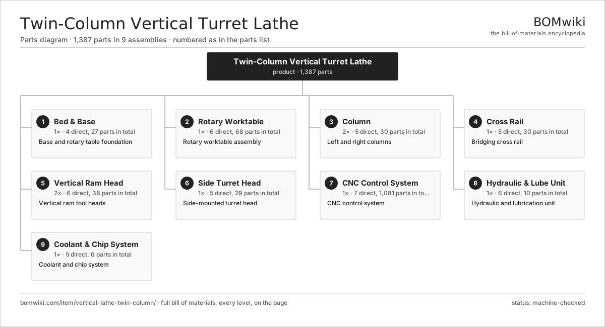
| # | Part | Qty | What it does |
|---|---|---|---|
| 1 | Bed & Base 4 parts | 1× | Base and rotary table foundation |
| 2 | Rotary Worktable 6 parts | 1× | Rotary worktable assembly |
| 3 | Column 5 parts | 2× | Left and right columns |
| 4 | Cross Rail 5 parts | 1× | Bridging cross rail |
| 5 | Vertical Ram Head 6 parts | 2× | Vertical ram tool heads |
| 6 | Side Turret Head 5 parts | 1× | Side-mounted turret head |
| 7 | CNC Control System 7 parts | 1× | CNC control system |
| 8 | Hydraulic & Lube Unit 6 parts | 1× | Hydraulic and lubrication unit |
| 9 | Coolant & Chip System 5 parts | 1× | Coolant and chip system |
3D model
No 3D model yet. Have a CAD file of this? Add a 3D model — STL renders right on this page; STEP, FreeCAD, and OpenSCAD sources are welcome too (openly licensed, like all 3D models on BOMwiki).
Build & assembly graph
expand / collapse · shared sub-assemblies converge · links to related products · est. labourTap an assembly to expand/collapse · tap a part to open it · use “Open page” for any node · drag to pan, scroll to zoom.
Bill of materials for Twin-Column Vertical Turret Lathe
9 top-level lines · 97 rows shown · 1,387 parts total · indented to 3 levels| # | Item / sub-assembly | Part no. | Qty/assy | Ext. qty | Parts | Type |
|---|---|---|---|---|---|---|
| 1 | Bed & Base 4 parts | vltc-bed | 1× | 1 | 27 | assembly |
| 1.1 | Base Casting | vltc-base-casting | 1× | 1 | · | part |
| 1.2 | Leveling Pad | vltc-leveling-pad | 12× | 12 | · | part |
| 1.3 | Hydrostatic Table Bearing 3 parts | vltc-table-bearing | 1× | 1 | 13 | assembly |
| 1.3.1 | Hydrostatic Pad | vltc-bearing-pad | 8× | 8 | · | part |
| 1.3.2 | O-Ring Set | oring-set | 1× | 1 | · | part |
| 1.3.3 | Pressure Sensor | pressure-sensor | 4× | 4 | · | part |
| 1.4 | Fastener Set | fastener-set | 1× | 1 | · | part |
| 2 | Rotary Worktable 6 parts | vltc-table | 1× | 1 | 68 | assembly |
| 2.1 | Faceplate | vltc-faceplate | 1× | 1 | · | part |
| 2.2 | Table Gear Ring | vltc-table-gear | 1× | 1 | · | part |
| 2.3 | Drive Pinion | vltc-table-pinion | 2× | 2 | · | part |
| 2.4 | Servo Motor 4 parts | servo-motor | 2× | 2 | 24 | assembly |
| 2.4.1 | Stator Assembly 3 parts + deeper › | stator-assembly | 1× | 2 | 3 | assembly |
| 2.4.2 | Rotor Assembly 4 parts + deeper › | rotor-assembly | 1× | 2 | 19 | assembly |
| 2.4.3 | Encoder | encoder | 1× | 2 | · | part |
| 2.4.4 | Motor Housing | motor-housing | 1× | 2 | · | part |
| 2.5 | Self-Centering Jaw 3 parts | vltc-jaw | 4× | 4 | 3 | assembly |
| 2.5.1 | Jaw Body | vltc-jaw-body | 1× | 4 | · | part |
| 2.5.2 | Jaw Clamping Screw | vltc-jaw-screw | 1× | 4 | · | part |
| 2.5.3 | Fastener Set | fastener-set | 1× | 4 | · | part |
| 2.6 | Ball Bearing | ball-bearing | 4× | 4 | · | part |
| 3 | Column 5 parts | vltc-column | 2× | 2 | 30 | assembly |
| 3.1 | Column Casting | vltc-column-casting | 1× | 2 | · | part |
| 3.2 | Linear Guide Rail | linear-guide | 2× | 4 | · | part |
| 3.3 | Ball Screw | ball-screw | 1× | 2 | · | part |
| 3.4 | Servo Motor 4 parts | servo-motor | 1× | 2 | 24 | assembly |
| 3.4.1 | Stator Assembly 3 parts + deeper › | stator-assembly | 1× | 2 | 3 | assembly |
| 3.4.2 | Rotor Assembly 4 parts + deeper › | rotor-assembly | 1× | 2 | 19 | assembly |
| 3.4.3 | Encoder | encoder | 1× | 2 | · | part |
| 3.4.4 | Motor Housing | motor-housing | 1× | 2 | · | part |
| 3.5 | Column Way Cover | vltc-column-cover | 2× | 4 | · | part |
| 4 | Cross Rail 5 parts | vltc-crossrail | 1× | 1 | 30 | assembly |
| 4.1 | Cross Rail Casting | vltc-rail-casting | 1× | 1 | · | part |
| 4.2 | Linear Guide Rail | linear-guide | 2× | 2 | · | part |
| 4.3 | Ball Screw | ball-screw | 1× | 1 | · | part |
| 4.4 | Servo Motor 4 parts | servo-motor | 1× | 1 | 24 | assembly |
| 4.4.1 | Stator Assembly 3 parts + deeper › | stator-assembly | 1× | 1 | 3 | assembly |
| 4.4.2 | Rotor Assembly 4 parts + deeper › | rotor-assembly | 1× | 1 | 19 | assembly |
| 4.4.3 | Encoder | encoder | 1× | 1 | · | part |
| 4.4.4 | Motor Housing | motor-housing | 1× | 1 | · | part |
| 4.5 | Rail Clamp Block | vltc-clamp-block | 2× | 2 | · | part |
| 5 | Vertical Ram Head 6 parts | vltc-ram-head | 2× | 2 | 38 | assembly |
| 5.1 | Tool Ram | vltc-ram | 1× | 2 | · | part |
| 5.2 | Indexing Turret 4 parts | vltc-turret | 1× | 2 | 5 | assembly |
| 5.2.1 | Turret Disc | vltc-turret-disc | 1× | 2 | · | part |
| 5.2.2 | Index Motor | vltc-index-motor | 1× | 2 | · | part |
| 5.2.3 | Curvic Coupling | vltc-curvic-coupling | 1× | 2 | · | part |
| 5.2.4 | Ball Bearing | ball-bearing | 2× | 4 | · | part |
| 5.3 | Ball Screw | ball-screw | 1× | 2 | · | part |
| 5.4 | Servo Motor 4 parts | servo-motor | 1× | 2 | 24 | assembly |
| 5.4.1 | Stator Assembly 3 parts + deeper › | stator-assembly | 1× | 2 | 3 | assembly |
| 5.4.2 | Rotor Assembly 4 parts + deeper › | rotor-assembly | 1× | 2 | 19 | assembly |
| 5.4.3 | Encoder | encoder | 1× | 2 | · | part |
| 5.4.4 | Motor Housing | motor-housing | 1× | 2 | · | part |
| 5.5 | Linear Guide Rail | linear-guide | 2× | 4 | · | part |
| 5.6 | Turret Tool Holder | vltc-tool-holder | 5× | 10 | · | part |
| 6 | Side Turret Head 5 parts | vltc-side-head | 1× | 1 | 29 | assembly |
| 6.1 | Side Slide | vltc-side-slide | 1× | 1 | · | part |
| 6.2 | Side Turret | vltc-side-turret | 1× | 1 | · | part |
| 6.3 | Ball Screw | ball-screw | 1× | 1 | · | part |
| 6.4 | Servo Motor 4 parts | servo-motor | 1× | 1 | 24 | assembly |
| 6.4.1 | Stator Assembly 3 parts + deeper › | stator-assembly | 1× | 1 | 3 | assembly |
| 6.4.2 | Rotor Assembly 4 parts + deeper › | rotor-assembly | 1× | 1 | 19 | assembly |
| 6.4.3 | Encoder | encoder | 1× | 1 | · | part |
| 6.4.4 | Motor Housing | motor-housing | 1× | 1 | · | part |
| 6.5 | Linear Guide Rail | linear-guide | 2× | 2 | · | part |
| 7 | CNC Control System 7 parts | vltc-cnc | 1× | 1 | 1,081 | assembly |
| 7.1 | CNC Unit 3 parts | vltc-cnc-unit | 1× | 1 | 303 | assembly |
| 7.1.1 | Bare PCB | pcb-bare | 1× | 1 | · | part |
| 7.1.2 | Microcontroller | mcu | 2× | 2 | · | part |
| 7.1.3 | SMD Passive (R/C/L) | smd-passives | 300× | 300 | · | part |
| 7.2 | Servo Drive 3 parts | vltc-servo-drive | 8× | 8 | 87 | assembly |
| 7.2.1 | Bare PCB | pcb-bare | 1× | 8 | · | part |
| 7.2.2 | Power MOSFET | mosfet | 6× | 48 | · | part |
| 7.2.3 | SMD Passive (R/C/L) | smd-passives | 80× | 640 | · | part |
| 7.3 | Power Supply | power-supply | 2× | 2 | · | part |
| 7.4 | Operator Console 3 parts | vltc-console | 1× | 1 | 3 | assembly |
| 7.4.1 | LCD Panel | lcd-panel | 1× | 1 | · | part |
| 7.4.2 | Bare PCB | pcb-bare | 1× | 1 | · | part |
| 7.4.3 | Microcontroller | mcu | 1× | 1 | · | part |
| 7.5 | Relay | relay | 16× | 16 | · | part |
| 7.6 | Wire Bundle | wire-bundle | 1× | 1 | · | part |
| 7.7 | Connector | connector | 60× | 60 | · | part |
| 8 | Hydraulic & Lube Unit 6 parts | vltc-hydraulics | 1× | 1 | 10 | assembly |
| 8.1 | Hydraulic Pump | vltc-hyd-pump | 2× | 2 | · | part |
| 8.2 | Hydraulic Tank | vltc-hyd-tank | 1× | 1 | · | part |
| 8.3 | Way Lubrication Pump | vltc-lube-pump | 1× | 1 | · | part |
| 8.4 | Valve Manifold | vltc-valve-block | 1× | 1 | · | part |
| 8.5 | Pressure Sensor | pressure-sensor | 4× | 4 | · | part |
| 8.6 | O-Ring Set | oring-set | 1× | 1 | · | part |
| 9 | Coolant & Chip System 5 parts | vltc-coolant | 1× | 1 | 6 | assembly |
| 9.1 | Coolant Pump | vltc-coolant-pump | 2× | 2 | · | part |
| 9.2 | Coolant Tank | vltc-coolant-tank | 1× | 1 | · | part |
| 9.3 | Chip Conveyor | vltc-chip-conveyor | 1× | 1 | · | part |
| 9.4 | Coolant Filter | vltc-coolant-filter | 1× | 1 | · | part |
| 9.5 | Drive Belt | drive-belt | 1× | 1 | · | part |
Related products
same domain, ranked by shared parts Railway Wheel Lathe
1,201 parts · shares 7 with this page
Spring End Grinding Machine
1,048 parts · shares 7 with this page
Electron Beam Welding Machine
670 parts · shares 6 with this page
Stud and Track Rollformer
517 parts · shares 5 with this page
Multi-Blanking Line
492 parts · shares 5 with this page
Railway Wheel Lathe
1,201 parts · shares 7 with this page
Spring End Grinding Machine
1,048 parts · shares 7 with this page
Electron Beam Welding Machine
670 parts · shares 6 with this page
Stud and Track Rollformer
517 parts · shares 5 with this page
Multi-Blanking Line
492 parts · shares 5 with this page
Sourcing: possible vendors
Prices, MOQ, and lead times are algorithmic estimates, not quotes, and not claims about these companies. Company mappings are curated by keyword; est. price band $10k–$1M. How estimates work| Vendor | HQ | Specialty | MOQ | Lead time |
|---|---|---|---|---|
|
🇩🇪DMG MORI
dmgmori.com ↗
|
Bielefeld, DE | Machine tools | 5 units | 12–20 wks |
|
🇯🇵Mazak
mazak.com ↗
|
Oguchi, JP | Machine tools | 5 units | 12–20 wks |
| haascnc.com ↗ | Oxnard, US | CNC machine tools | 5 units | 12–20 wks |
|
🇯🇵Okuma
okuma.com ↗
|
Niwa, JP | Machine tools | 5 units | 12–20 wks |
|
🇩🇪Trumpf
trumpf.com ↗
|
Ditzingen, DE | Laser & sheet-metal machines | 5 units | 12–20 wks |
849-word article