Slotting Machine
ProductOverview
A slotting machine, often called a slotter or vertical shaper, cuts with a single-point tool that reciprocates straight up and down. It is essentially a shaper turned on its side: the tool moves vertically while the workpiece is fed beneath it on a Rotary Worktable. The vertical stroke makes it the natural tool for internal features that a horizontal shaper or a milling cutter cannot easily reach, internal keyways, splines, internal gear teeth, square and hexagonal holes, and slots in blind bores. The cutting tool descends through the work on the Ram Assembly, removes a chip, lifts clear on the return, and the Feed System indexes the work a small amount before the next stroke. Because the table can move in cross, longitudinal and rotary directions, the slotter can also generate curved and circular profiles that follow the table rotation.
Base, column and saddle
The machine is built on a grey iron Base and Column assembly. The Base Casting supports everything and houses the coolant reservoir. The Column rises at the back with scraped vertical ways that guide the ram. In front of the column, a Cross Saddle slides on the base and carries the rotary table, giving the cross and longitudinal feed motions. Clearance in both the ram ways and the saddle ways is controlled by Way Gibs strips so that the tool path stays straight and square as the machine wears. Grey iron is chosen for its damping, which matters because the interrupted cut of a reciprocating tool would otherwise set up chatter that spoils the surface.
Ram and tool head
The Ram is a hardened steel member that reciprocates vertically on the Ram Slide. Two adjustments tailor the stroke to the job: the Stroke Length Adjuster changes the crank throw to set how long the stroke is, and the Stroke Position Adjuster shifts the whole reciprocation up or down so the cutting window lines up with the work. At the foot of the ram sits the Tool Head. The Tool Post clamps a single-point Tool Bit ground to the shape of the slot or profile. On the return stroke the tool would drag against the freshly cut wall, so a Tool Relief Mechanism tilts or lifts it slightly to clear the surface, then returns it for the next cut. This relief is the same idea a planer clapper box uses, adapted to vertical motion.
Rotary table and indexing
The defining feature of a slotter is its Rotary Worktable. The slotted Table Casting sits on the saddle and rotates on a Worm and Wheel drive. Rotation does two jobs. First, with the tool fixed and the table turning slowly, the slotter generates circular and curved profiles, internal and external. Second, for cutting evenly spaced features such as the teeth of an internal gear or the slots of a spline, an Index Plate divides a full turn into precise angles so the operator can advance the table by an exact division between cuts. Once positioned, a Table Clamp locks the table against the cutting load. The combination of vertical cutting and a rotary, cross and longitudinal table is what lets one machine produce internal gears and odd internal shapes that no rotating cutter can.
Feed and drive
The Feed System advances the work between strokes. Feed Screws drive the saddle in cross and longitudinal directions, a Feed Ratchet indexes the chosen feed once per stroke, and a Feed Selector lever picks the direction and rate, including rotary feed of the table through a Helical Gear Pair. Feeds run from about 0.05 to 0.5 mm per stroke. Power comes from the Drive System: a Drive Motor of 3–11 kW turns through a Helical Gearbox and Drive Belt to an adjustable Crank Disc, whose Connecting Rod converts rotation into the vertical ram stroke on Ball Bearing supports. The crank gives a quick-return characteristic: the cutting downstroke runs slower than the idle upstroke, which keeps cutting forces moderate while shortening cycle time.
Coolant, electrical and control
The Coolant System handles heat and chips. A Coolant Pump draws from the Coolant Tank in the base and feeds a Coolant Nozzle aimed at the tool tip, washing chips out of deep blind slots where they would otherwise pack. The Electrical System system is straightforward: a Motor Contactor switches the motor, a few Relay units and a Power Supply run the control circuit, wired through a Wire Bundle and Connector set with safety interlocks on the guards.
Materials, variants and use
Castings are grey iron for stiffness and damping; the ram and tool head are alloy steels hardened at the wear surfaces. Slotters range from small toolroom machines with a 50 mm stroke up to heavy production units with a 400 mm stroke and a 900 mm table. They are used for cutting internal keyways and splines, producing internal gears and ratchets, squaring blind holes, and machining odd internal profiles in dies and moulds. Tolerances of IT8 to IT9 are routine, and finer work is possible with light finishing cuts. Although CNC wire EDM and broaching have taken over high-volume internal work, the slotting machine remains the practical, low-cost choice for one-off and short-run internal features, repair work and toolroom tasks, because a single inexpensive tool covers a wide variety of shapes.
Slotting Machine parts and their functions
8 top-level parts · 58 parts in total · full bill of materials below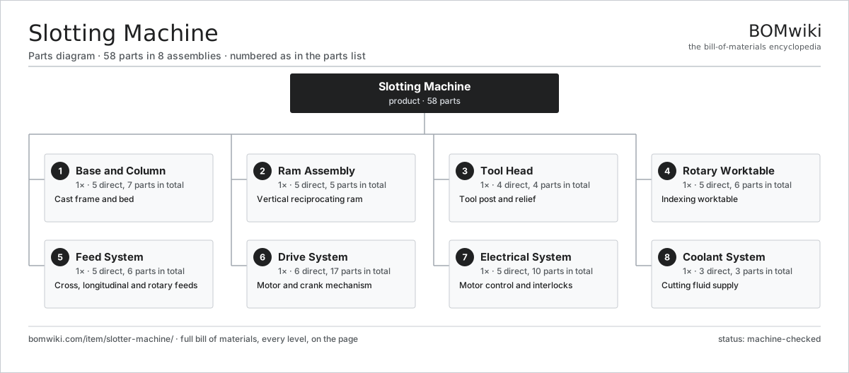
| # | Part | Qty | What it does |
|---|---|---|---|
| 1 | Base and Column 5 parts | 1× | Cast frame and bed |
| 2 | Ram Assembly 5 parts | 1× | Vertical reciprocating ram |
| 3 | Tool Head 4 parts | 1× | Tool post and relief |
| 4 | Rotary Worktable 5 parts | 1× | Indexing worktable |
| 5 | Feed System 5 parts | 1× | Cross, longitudinal and rotary feeds |
| 6 | Drive System 6 parts | 1× | Motor and crank mechanism |
| 7 | Electrical System 5 parts | 1× | Motor control and interlocks |
| 8 | Coolant System 3 parts | 1× | Cutting fluid supply |
3D model
No 3D model yet. Have a CAD file of this? Add a 3D model — STL renders right on this page; STEP, FreeCAD, and OpenSCAD sources are welcome too (openly licensed, like all 3D models on BOMwiki).
Build & assembly graph
expand / collapse · shared sub-assemblies converge · links to related products · est. labourTap an assembly to expand/collapse · tap a part to open it · use “Open page” for any node · drag to pan, scroll to zoom.
Bill of materials for Slotting Machine
8 top-level lines · 50 rows shown · 58 parts total · indented to 3 levels| # | Item / sub-assembly | Part no. | Qty/assy | Ext. qty | Parts | Type |
|---|---|---|---|---|---|---|
| 1 | Base and Column 5 parts | slotter-machine-base-column | 1× | 1 | 7 | assembly |
| 1.1 | Base Casting | slotter-machine-base-casting | 1× | 1 | · | part |
| 1.2 | Column | slotter-machine-column | 1× | 1 | · | part |
| 1.3 | Cross Saddle | slotter-machine-saddle | 1× | 1 | · | part |
| 1.4 | Way Gibs | slotter-machine-ways-gib | 2× | 2 | · | part |
| 1.5 | Fastener Set | fastener-set | 2× | 2 | · | part |
| 2 | Ram Assembly 5 parts | slotter-machine-ram-assembly | 1× | 1 | 5 | assembly |
| 2.1 | Ram | slotter-machine-ram | 1× | 1 | · | part |
| 2.2 | Ram Slide | slotter-machine-ram-slide | 1× | 1 | · | part |
| 2.3 | Stroke Length Adjuster | slotter-machine-stroke-adjuster | 1× | 1 | · | part |
| 2.4 | Stroke Position Adjuster | slotter-machine-stroke-position-adjuster | 1× | 1 | · | part |
| 2.5 | Fastener Set | fastener-set | 1× | 1 | · | part |
| 3 | Tool Head 4 parts | slotter-machine-tool-head | 1× | 1 | 4 | assembly |
| 3.1 | Tool Post | slotter-machine-tool-post | 1× | 1 | · | part |
| 3.2 | Tool Bit | slotter-machine-tool-bit | 1× | 1 | · | part |
| 3.3 | Tool Relief Mechanism | slotter-machine-relief-mechanism | 1× | 1 | · | part |
| 3.4 | Fastener Set | fastener-set | 1× | 1 | · | part |
| 4 | Rotary Worktable 5 parts | slotter-machine-rotary-table | 1× | 1 | 6 | assembly |
| 4.1 | Table Casting | slotter-machine-table-casting | 1× | 1 | · | part |
| 4.2 | Worm and Wheel | slotter-machine-worm-gear | 1× | 1 | · | part |
| 4.3 | Index Plate | slotter-machine-index-plate | 1× | 1 | · | part |
| 4.4 | Table Clamp | slotter-machine-table-clamp | 1× | 1 | · | part |
| 4.5 | Ball Bearing | ball-bearing | 2× | 2 | · | part |
| 5 | Feed System 5 parts | slotter-machine-feed-system | 1× | 1 | 6 | assembly |
| 5.1 | Feed Screws | slotter-machine-feed-screws | 2× | 2 | · | part |
| 5.2 | Feed Ratchet | slotter-machine-feed-ratchet | 1× | 1 | · | part |
| 5.3 | Feed Selector | slotter-machine-feed-selector | 1× | 1 | · | part |
| 5.4 | Helical Gear Pair | gear-pair | 1× | 1 | · | part |
| 5.5 | Fastener Set | fastener-set | 1× | 1 | · | part |
| 6 | Drive System 6 parts | slotter-machine-drive-system | 1× | 1 | 17 | assembly |
| 6.1 | Drive Motor | slotter-machine-drive-motor | 1× | 1 | · | part |
| 6.2 | Helical Gearbox 4 parts | gearbox | 1× | 1 | 9 | assembly |
| 6.2.1 | Helical Gear Pair | gear-pair | 2× | 2 | · | part |
| 6.2.2 | Gearbox Housing | gearbox-housing | 1× | 1 | · | part |
| 6.2.3 | Ball Bearing | ball-bearing | 4× | 4 | · | part |
| 6.2.4 | Oil Seal | oil-seal | 2× | 2 | · | part |
| 6.3 | Crank Disc | slotter-machine-crank-disc | 1× | 1 | · | part |
| 6.4 | Connecting Rod | slotter-machine-connecting-rod | 1× | 1 | · | part |
| 6.5 | Drive Belt | drive-belt | 1× | 1 | · | part |
| 6.6 | Ball Bearing | ball-bearing | 4× | 4 | · | part |
| 7 | Electrical System 5 parts | slotter-machine-electrical | 1× | 1 | 10 | assembly |
| 7.1 | Motor Contactor | slotter-machine-contactor | 1× | 1 | · | part |
| 7.2 | Relay | relay | 2× | 2 | · | part |
| 7.3 | Power Supply | power-supply | 1× | 1 | · | part |
| 7.4 | Wire Bundle | wire-bundle | 1× | 1 | · | part |
| 7.5 | Connector | connector | 5× | 5 | · | part |
| 8 | Coolant System 3 parts | slotter-machine-coolant-system | 1× | 1 | 3 | assembly |
| 8.1 | Coolant Pump | slotter-machine-coolant-pump | 1× | 1 | · | part |
| 8.2 | Coolant Tank | slotter-machine-coolant-tank | 1× | 1 | · | part |
| 8.3 | Coolant Nozzle | slotter-machine-coolant-nozzle | 1× | 1 | · | part |
Related products
same domain, ranked by shared parts Flat-Die Thread Roller
65 parts · shares 4 with this page
Flat-Die Thread Roller
65 parts · shares 4 with this page
 Keyseating Machine
55 parts · shares 4 with this page
Roller Leveler
469 parts · shares 4 with this page
Strip Tension Leveler
513 parts · shares 4 with this page
Cut-to-Length Line
500 parts · shares 3 with this page
Roll Tapping Machine
82 parts · shares 3 with this page
Keyseating Machine
55 parts · shares 4 with this page
Roller Leveler
469 parts · shares 4 with this page
Strip Tension Leveler
513 parts · shares 4 with this page
Cut-to-Length Line
500 parts · shares 3 with this page
Roll Tapping Machine
82 parts · shares 3 with this page
Sourcing: possible vendors
Prices, MOQ, and lead times are algorithmic estimates, not quotes, and not claims about these companies. Company mappings are curated by keyword; est. price band $10k–$1M. How estimates work| Vendor | HQ | Specialty | MOQ | Lead time |
|---|---|---|---|---|
|
🇩🇪DMG MORI
dmgmori.com ↗
|
Bielefeld, DE | Machine tools | 5 units | 12–20 wks |
|
🇯🇵Mazak
mazak.com ↗
|
Oguchi, JP | Machine tools | 5 units | 12–20 wks |
| haascnc.com ↗ | Oxnard, US | CNC machine tools | 5 units | 12–20 wks |
|
🇯🇵Okuma
okuma.com ↗
|
Niwa, JP | Machine tools | 5 units | 12–20 wks |
|
🇩🇪Trumpf
trumpf.com ↗
|
Ditzingen, DE | Laser & sheet-metal machines | 5 units | 12–20 wks |
949-word article