Shaft Straightening Press
ProductOverview
A shaft straightening press removes the bends and runout that appear in long, slender shafts after turning, grinding, heat treatment or transport. When a shaft is hardened or welded, internal stresses release unevenly and the part bows by a few tenths of a millimetre. That bow shows up as total indicated runout (TIR) when the shaft spins, and it causes vibration, bearing wear and balance problems downstream. The press corrects it by supporting the shaft on a Workholding System system, finding the high point with a Measuring System, rotating the shaft so the high point faces up with the Rotation Drive, then pushing down with the Ram Assembly just past the elastic limit so the metal yields back toward straight. The whole sequence is coordinated by the Control System, and on automatic machines it repeats measure, press and recheck until the shaft is inside tolerance.
Frame and reaction structure
Every pressing stroke creates a large reaction force, so the Press Frame is the heaviest single part of the machine. Smaller benchtop units use a C-frame, while machines above roughly 250 kN use a four-column design with pre-tensioned Tie Rods that close the load path symmetrically and limit frame deflection. The Frame Weldment is built from box-section S355 steel and stress relieved after welding so it holds its geometry through millions of cycles. The shaft rests on the Bed Plate, a ground and induction-hardened lower platen that carries the fixtures and resists local denting where the vee-blocks sit. The Guide Bushings keep the ram square to the bed; if the ram tilts, the pressing force develops a side component that twists the shaft instead of bending it cleanly.
Ram and pressing tool
The corrective load comes from the Main Hydraulic Cylinder, a double-acting hydraulic cylinder with a 100–250 mm bore that produces up to 600 kN at 250 bar. The cylinder drives the Ram Slide, which carries a replaceable Pressing Tool with a radiused nose hardened to about 58 HRC. The radius matters: too sharp a nose marks the shaft, too broad a nose spreads the load and reduces local yield. Mounted in line with the ram is a Press Load Cell that reads pressing force to better than half a percent. Straightening is a yield operation, so the control needs both displacement and force feedback to push the shaft just past its elastic limit without cracking it or leaving residual stress that springs back later. Internal sealing relies on a standard O-Ring Set and rod Oil Seal pair.
Hydraulic power unit
The Hydraulic Power Unit supplies oil to the ram. A Variable Displacement Pump of the variable displacement axial-piston type, driven by a Pump Motor of 7.5–22 kW, delivers 20–60 L/min. Oil is held in the Oil Tank, passed through a Return Filter to keep contamination away from the valves, and cooled by the Oil Cooler so viscosity stays stable. The key element for straightening quality is the Proportional Pressure Valve. Because the operation depends on controlled overbend, the valve regulates ram pressure in a closed loop against the load cell, letting the PLC command a precise force and dwell rather than simply driving the ram to a hard stop.
Workholding and rotation
The shaft is supported by the Workholding System system. Two Vee Blocks slide along the bed to suit the shaft length and act as the bending supports on either side of the press point. For shafts with centre holes, End Centres locate the part on its true axis so measurement reflects the geometry the shaft will run on in service. Roller Rests with polyurethane tyres carry the weight while the shaft turns, riding on Ball Bearing sets. Rotation is handled by the Rotation Drive, where a Servo Motor and Helical Gearbox turn the shaft through a Drive Chuck. The servo can spin the shaft for measurement and then index it precisely so the bend high point sits directly under the pressing tool.
Measurement and correction cycle
Straightening accuracy depends entirely on knowing where the bend is. The Measuring System uses one or two Runout Probe sensors, usually LVDT or inductive types reading to 1 micron, mounted against the shaft. As the Angle Encoder tracks angular position, the Probe Controller builds a runout map and finds both the magnitude and the angle of the maximum deviation. The Control System then rotates the shaft so the high point faces the ram, calculates the overbend needed from the shaft diameter and material, and commands the press. After the stroke it rechecks the runout. Hardened steel springs back, so the press always bends slightly beyond straight; the PLC learns the spring-back from the recheck and refines the next correction. The HMI Panel shows a polar plot of runout before and after, and stores part programs for repeated shaft types.
Materials, variants and use
Frames are S355 steel; bed plates and pressing tools are alloy steels such as 42CrMo4, hardened where they contact the work. Machines range from manual two-tonne benchtop presses used by motor rewind shops to fully automatic cells that straighten thousands of motor shafts, axles, camshafts and turbine rotors per shift. Larger variants add multiple press stations and automatic loading. The shared elements across all of them are a stiff frame, a force-controlled ram, accurate runout measurement and a rotation drive that indexes the bend to the tool. Typical results bring a shaft from several tenths of a millimetre of bow down to 0.02–0.05 mm TIR, well within the balance and bearing requirements of most rotating machinery.
Shaft Straightening Press parts and their functions
7 top-level parts · 93 parts in total · full bill of materials below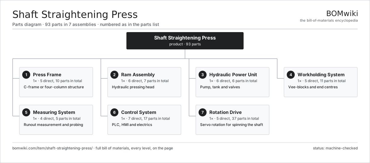
| # | Part | Qty | What it does |
|---|---|---|---|
| 1 | Press Frame 5 parts | 1× | C-frame or four-column structure |
| 2 | Ram Assembly 6 parts | 1× | Hydraulic pressing head |
| 3 | Hydraulic Power Unit 6 parts | 1× | Pump, tank and valves |
| 4 | Workholding System 5 parts | 1× | Vee-blocks and end centres |
| 5 | Measuring System 4 parts | 1× | Runout measurement and probing |
| 6 | Control System 7 parts | 1× | PLC, HMI and electrics |
| 7 | Rotation Drive 5 parts | 1× | Servo rotation for spinning the shaft |
3D model
No 3D model yet. Have a CAD file of this? Add a 3D model — STL renders right on this page; STEP, FreeCAD, and OpenSCAD sources are welcome too (openly licensed, like all 3D models on BOMwiki).
Build & assembly graph
expand / collapse · shared sub-assemblies converge · links to related products · est. labourTap an assembly to expand/collapse · tap a part to open it · use “Open page” for any node · drag to pan, scroll to zoom.
Bill of materials for Shaft Straightening Press
7 top-level lines · 53 rows shown · 93 parts total · indented to 3 levels| # | Item / sub-assembly | Part no. | Qty/assy | Ext. qty | Parts | Type |
|---|---|---|---|---|---|---|
| 1 | Press Frame 5 parts | shaft-straightening-press-frame | 1× | 1 | 10 | assembly |
| 1.1 | Frame Weldment | shaft-straightening-press-frame-weldment | 1× | 1 | · | part |
| 1.2 | Bed Plate | shaft-straightening-press-bed-plate | 1× | 1 | · | part |
| 1.3 | Tie Rods | shaft-straightening-press-tie-rods | 4× | 4 | · | part |
| 1.4 | Guide Bushings | shaft-straightening-press-guide-bushings | 2× | 2 | · | part |
| 1.5 | Fastener Set | fastener-set | 2× | 2 | · | part |
| 2 | Ram Assembly 6 parts | shaft-straightening-press-ram-assembly | 1× | 1 | 7 | assembly |
| 2.1 | Main Hydraulic Cylinder | shaft-straightening-press-main-cylinder | 1× | 1 | · | part |
| 2.2 | Ram Slide | shaft-straightening-press-ram-slide | 1× | 1 | · | part |
| 2.3 | Press Load Cell | shaft-straightening-press-load-cell | 1× | 1 | · | part |
| 2.4 | Pressing Tool | shaft-straightening-press-pressing-tool | 1× | 1 | · | part |
| 2.5 | O-Ring Set | oring-set | 1× | 1 | · | part |
| 2.6 | Oil Seal | oil-seal | 2× | 2 | · | part |
| 3 | Hydraulic Power Unit 6 parts | shaft-straightening-press-hydraulic-power-unit | 1× | 1 | 6 | assembly |
| 3.1 | Variable Displacement Pump | shaft-straightening-press-hpu-pump | 1× | 1 | · | part |
| 3.2 | Pump Motor | shaft-straightening-press-hpu-motor | 1× | 1 | · | part |
| 3.3 | Oil Tank | shaft-straightening-press-hpu-tank | 1× | 1 | · | part |
| 3.4 | Proportional Pressure Valve | shaft-straightening-press-proportional-valve | 1× | 1 | · | part |
| 3.5 | Oil Cooler | shaft-straightening-press-hpu-cooler | 1× | 1 | · | part |
| 3.6 | Return Filter | shaft-straightening-press-hpu-filter | 1× | 1 | · | part |
| 4 | Workholding System 5 parts | shaft-straightening-press-workholding | 1× | 1 | 11 | assembly |
| 4.1 | Vee Blocks | shaft-straightening-press-vee-blocks | 2× | 2 | · | part |
| 4.2 | End Centres | shaft-straightening-press-end-centres | 2× | 2 | · | part |
| 4.3 | Roller Rests | shaft-straightening-press-roller-rests | 2× | 2 | · | part |
| 4.4 | Ball Bearing | ball-bearing | 4× | 4 | · | part |
| 4.5 | Fastener Set | fastener-set | 1× | 1 | · | part |
| 5 | Measuring System 4 parts | shaft-straightening-press-measuring-system | 1× | 1 | 5 | assembly |
| 5.1 | Runout Probe | shaft-straightening-press-dial-probe | 2× | 2 | · | part |
| 5.2 | Angle Encoder | shaft-straightening-press-angle-encoder | 1× | 1 | · | part |
| 5.3 | Probe Controller | shaft-straightening-press-probe-controller | 1× | 1 | · | part |
| 5.4 | Wire Bundle | wire-bundle | 1× | 1 | · | part |
| 6 | Control System 7 parts | shaft-straightening-press-control-system | 1× | 1 | 17 | assembly |
| 6.1 | PLC | shaft-straightening-press-plc | 1× | 1 | · | part |
| 6.2 | HMI Panel | shaft-straightening-press-hmi | 1× | 1 | · | part |
| 6.3 | Servo Drive | shaft-straightening-press-servo-drive | 1× | 1 | · | part |
| 6.4 | Power Supply | power-supply | 1× | 1 | · | part |
| 6.5 | Relay | relay | 4× | 4 | · | part |
| 6.6 | Connector | connector | 8× | 8 | · | part |
| 6.7 | Wire Bundle | wire-bundle | 1× | 1 | · | part |
| 7 | Rotation Drive 5 parts | shaft-straightening-press-rotation-drive | 1× | 1 | 37 | assembly |
| 7.1 | Servo Motor 4 parts | servo-motor | 1× | 1 | 24 | assembly |
| 7.1.1 | Stator Assembly 3 parts + deeper › | stator-assembly | 1× | 1 | 3 | assembly |
| 7.1.2 | Rotor Assembly 4 parts + deeper › | rotor-assembly | 1× | 1 | 19 | assembly |
| 7.1.3 | Encoder | encoder | 1× | 1 | · | part |
| 7.1.4 | Motor Housing | motor-housing | 1× | 1 | · | part |
| 7.2 | Helical Gearbox 4 parts | gearbox | 1× | 1 | 9 | assembly |
| 7.2.1 | Helical Gear Pair | gear-pair | 2× | 2 | · | part |
| 7.2.2 | Gearbox Housing | gearbox-housing | 1× | 1 | · | part |
| 7.2.3 | Ball Bearing | ball-bearing | 4× | 4 | · | part |
| 7.2.4 | Oil Seal | oil-seal | 2× | 2 | · | part |
| 7.3 | Drive Chuck | shaft-straightening-press-drive-chuck | 1× | 1 | · | part |
| 7.4 | Ball Bearing | ball-bearing | 2× | 2 | · | part |
| 7.5 | Fastener Set | fastener-set | 1× | 1 | · | part |
Related products
same domain, ranked by shared parts Rotary Draw Bender
821 parts · shares 5 with this page
Strip Tension Leveler
513 parts · shares 5 with this page
Roll Tapping Machine
82 parts · shares 4 with this page
Rotary Draw Bender
821 parts · shares 5 with this page
Strip Tension Leveler
513 parts · shares 5 with this page
Roll Tapping Machine
82 parts · shares 4 with this page
 Flat-Die Thread Roller
65 parts · shares 3 with this page
Flat-Die Thread Roller
65 parts · shares 3 with this page
Sourcing: possible vendors
Prices, MOQ, and lead times are algorithmic estimates, not quotes, and not claims about these companies. Company mappings are curated by keyword; est. price band $10k–$1M. How estimates work| Vendor | HQ | Specialty | MOQ | Lead time |
|---|---|---|---|---|
|
🇩🇪DMG MORI
dmgmori.com ↗
|
Bielefeld, DE | Machine tools | 5 units | 12–20 wks |
|
🇯🇵Mazak
mazak.com ↗
|
Oguchi, JP | Machine tools | 5 units | 12–20 wks |
| haascnc.com ↗ | Oxnard, US | CNC machine tools | 5 units | 12–20 wks |
|
🇯🇵Okuma
okuma.com ↗
|
Niwa, JP | Machine tools | 5 units | 12–20 wks |
|
🇩🇪Trumpf
trumpf.com ↗
|
Ditzingen, DE | Laser & sheet-metal machines | 5 units | 12–20 wks |
1,031-word article