Temper Rolling Mill
ProductThe Temper Rolling Mill is a single 4-high rolling stand that takes annealed strip and applies a very light reduction, typically 0.5-3% elongation, to finish its mechanical and surface properties. It does not change gauge in any meaningful way. The job is to remove the yield-point elongation that annealing leaves in low-carbon steel, set a controlled surface roughness, and improve flatness before the strip is shipped or sent to coating. Because the reduction is small, every part of the mill is built around precise control of a light load rather than the brute force of a cold-reduction mill.
Purpose of temper rolling
Fully annealed low-carbon steel has a sharp yield point. When it is later formed, that yield point releases unevenly and leaves stretcher-strain marks, also called Luders bands, on the part surface. A pass through the roll set at a small fixed elongation works the surface grains just enough to eliminate the discontinuous yield, so the steel deforms smoothly when the customer presses it. The same pass transfers a defined roughness from the work rolls to the strip, which controls how the strip takes paint and how it behaves in the press. The third function is flatness: light rolling under tension flattens residual shape defects such as edge wave and center buckle. The elongation controller ties these together, since the amount of extension sets how completely the yield point is killed.
Mill stand and housing
The mill stand is a closed frame. Two cast-steel housing posts form the load window, closed at the top by two housing caps and pulled together by four pre-tensioned tie rods so the assembly reacts the roll-separating force as one stiff loop. Frame stiffness matters more here than peak strength, because a flexible stand would let the gap drift and spoil the elongation. Sole plates align the housing to the foundation. Bronze-faced liner plates and window guides line the chock windows so the chocks move only on the vertical axis, with worn liners replaced rather than the casting.
Roll set and chocks
Two work rolls do the rolling, backed by two large back-up rolls that limit work-roll deflection across the width. The work-roll barrel carries an electro-discharge texture, a pattern of fine pits ground in by EDT, which transfers a target roughness to the strip. A bright finish roll is fitted instead when a low-Ra surface is wanted. The work rolls run in work-roll chocks on ball bearings, while the heavily loaded back-up necks run in back-up-roll chocks carrying hydrodynamic oil-film bearings. Roll neck seals and oil seals keep bearing oil in and temper solution out of the necks.
Roll-force, gap, and elongation control
This is the defining control problem of the mill. The strip leaves slightly longer than it enters, and that difference must be held to a fraction of a percent across the whole coil. Two hydraulic gap control cylinders, fed through high-response servo valves, set the gap and the roll-separating force. Gap position sensors and roll-force load cells close the loop on each side. The elongation controller reads the stretch encoders at entry and exit, computes the actual extension from the speed ratio, and trims roll force and strip tension to hold the setpoint to about +/-0.05%. Four roll bending cylinders bend the work rolls to correct shape across the width while the elongation loop runs.
Tension and coil handling
Tension is part of the rolling mechanism, not just transport. The payoff reel pays the annealed coil off under back-tension and the tension reel recoils the strip under front-tension, both on segmented reel mandrels driven by reel drive motors. Between them, an entry and an exit bridle of rubber-lagged bridle rolls set the strip tension by controlled speed difference, which decides how much of the elongation comes from tension versus roll force. Deflector rolls and strip guides hold the pass line, a tensiometer measures actual tension, and the stretch encoders feed the elongation loop.
Solution, surface, and the rest of the line
In wet temper rolling the temper solution system lays a thin film on the strip so friction and texture transfer stay even. A solution pump draws from the solution tank through filters to applicator headers and spray nozzles; wringer rolls and a blow-off header dry the strip, and cleaning brushes keep the work-roll texture clear. A dry skin-pass mill omits this system. The main motor drives through a gear distributor and two spindles. The lube unit and hydraulic power unit feed the bearings and cylinders, and the control system runs drive, gauge, and elongation control with pressure sensors, load cells, and a roughness monitor. The same stand is run as a temper mill for soft tempers, as a skin-pass for very light passes, or as a double-cold-reduction mill when a heavier extension is wanted after annealing.
Temper Rolling Mill parts and their functions
8 top-level parts · 692 parts in total · full bill of materials below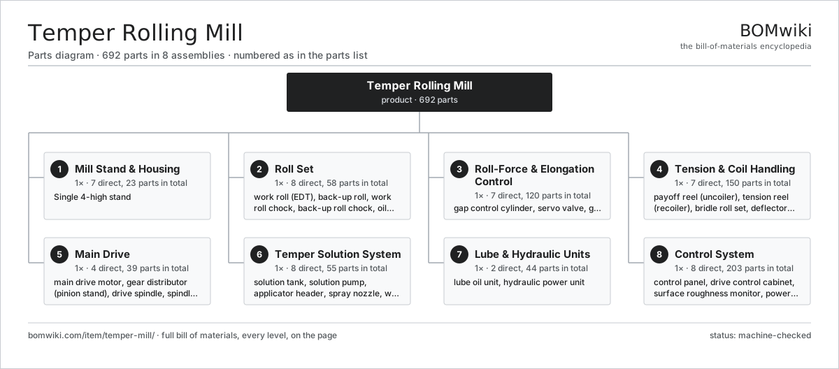
| # | Part | Qty | What it does |
|---|---|---|---|
| 1 | Mill Stand & Housing 7 parts | 1× | Single 4-high stand |
| 2 | Roll Set 8 parts | 1× | Two textured work rolls backed by two large back-up rolls in four chocks. |
| 3 | Roll-Force & Elongation Control 7 parts | 1× | Hydraulic gap actuators with load and position feedback that hold the percent elongation to tolerance. |
| 4 | Tension & Coil Handling 7 parts | 1× | Payoff and tension reels with entry and exit bridles that set the strip tension elongation works against. |
| 5 | Main Drive 4 parts | 1× | Main motor through a gear distributor and two spindles to the work rolls. |
| 6 | Temper Solution System 8 parts | 1× | Applies and removes a thin temper solution that controls friction and texture transfer in wet temper rolling. |
| 7 | Lube & Hydraulic Units 2 parts | 1× | Bearing oil circulation and the hydraulic power that drives the gap and bending cylinders. |
| 8 | Control System 8 parts | 1× | Drive, gauge, and elongation control with the sensor and wiring set the loops depend on. |
3D model
No 3D model yet. Have a CAD file of this? Add a 3D model — STL renders right on this page; STEP, FreeCAD, and OpenSCAD sources are welcome too (openly licensed, like all 3D models on BOMwiki).
Build & assembly graph
expand / collapse · shared sub-assemblies converge · links to related products · est. labourTap an assembly to expand/collapse · tap a part to open it · use “Open page” for any node · drag to pan, scroll to zoom.
Bill of materials for Temper Rolling Mill
8 top-level lines · 130 rows shown · 692 parts total · indented to 3 levels| # | Item / sub-assembly | Part no. | Qty/assy | Ext. qty | Parts | Type |
|---|---|---|---|---|---|---|
| 1 | Mill Stand & Housing 7 parts | temper-mill-stand | 1× | 1 | 23 | assembly |
| 1.1 | Housing Post | temper-mill-housing-post | 2× | 2 | · | part |
| 1.2 | Housing Cap | temper-mill-housing-cap | 2× | 2 | · | part |
| 1.3 | Tie Rod | temper-mill-tie-rod | 4× | 4 | · | part |
| 1.4 | Sole Plate | temper-mill-sole-plate | 2× | 2 | · | part |
| 1.5 | Window Liner Plate | temper-mill-liner-plate | 8× | 8 | · | part |
| 1.6 | Window Guide | temper-mill-window-guide | 4× | 4 | · | part |
| 1.7 | Fastener Set | fastener-set | 1× | 1 | · | part |
| 2 | Roll Set 8 parts | temper-mill-roll-set | 1× | 1 | 58 | assembly |
| 2.1 | Work Roll (EDT) | temper-mill-work-roll | 2× | 2 | · | part |
| 2.2 | Back-up Roll | temper-mill-backup-roll | 2× | 2 | · | part |
| 2.3 | Work Roll Chock 3 parts | temper-mill-work-roll-chock | 2× | 2 | 3 | assembly |
| 2.3.1 | Ball Bearing | ball-bearing | 1× | 2 | · | part |
| 2.3.2 | Oil Seal | oil-seal | 1× | 2 | · | part |
| 2.3.3 | Chock Body | temper-mill-chock-body | 1× | 2 | · | part |
| 2.4 | Back-up Roll Chock 3 parts | temper-mill-backup-roll-chock | 2× | 2 | 6 | assembly |
| 2.4.1 | Oil-Film Bearing 3 parts + deeper › | temper-mill-oilfilm-bearing | 1× | 2 | 4 | assembly |
| 2.4.2 | Oil Seal | oil-seal | 1× | 2 | · | part |
| 2.4.3 | Chock Body | temper-mill-chock-body | 1× | 2 | · | part |
| 2.5 | Oil-Film Bearing 3 parts | temper-mill-oilfilm-bearing | 4× | 4 | 4 | assembly |
| 2.5.1 | Bearing Bushing | temper-mill-bearing-bushing | 1× | 4 | · | part |
| 2.5.2 | Bearing Sleeve | temper-mill-bearing-sleeve | 1× | 4 | · | part |
| 2.5.3 | Oil Seal | oil-seal | 2× | 8 | · | part |
| 2.6 | Ball Bearing | ball-bearing | 4× | 4 | · | part |
| 2.7 | Roll Neck Seal | temper-mill-neck-seal | 8× | 8 | · | part |
| 2.8 | Oil Seal | oil-seal | 8× | 8 | · | part |
| 3 | Roll-Force & Elongation Control 7 parts | temper-mill-rollforce-system | 1× | 1 | 120 | assembly |
| 3.1 | Gap Control Cylinder 4 parts | temper-mill-gap-cylinder | 2× | 2 | 6 | assembly |
| 3.1.1 | Cylinder Body | temper-mill-cylinder-body | 1× | 2 | · | part |
| 3.1.2 | Cylinder Piston | temper-mill-cylinder-piston | 1× | 2 | · | part |
| 3.1.3 | O-Ring Set | oring-set | 2× | 4 | · | part |
| 3.1.4 | Oil Seal | oil-seal | 2× | 4 | · | part |
| 3.2 | Servo Valve | temper-mill-servo-valve | 2× | 2 | · | part |
| 3.3 | Gap Position Sensor | temper-mill-position-sensor | 2× | 2 | · | part |
| 3.4 | Roll-Force Load Cell | temper-mill-load-cell | 2× | 2 | · | part |
| 3.5 | Roll Bending Cylinder 2 parts | temper-mill-bending-cylinder | 4× | 4 | 3 | assembly |
| 3.5.1 | Cylinder Body | temper-mill-cylinder-body | 1× | 4 | · | part |
| 3.5.2 | O-Ring Set | oring-set | 2× | 8 | · | part |
| 3.6 | Elongation Controller 4 parts | temper-mill-elongation-controller | 1× | 1 | 86 | assembly |
| 3.6.1 | Bare PCB | pcb-bare | 1× | 1 | · | part |
| 3.6.2 | Microcontroller | mcu | 1× | 1 | · | part |
| 3.6.3 | Connector | connector | 4× | 4 | · | part |
| 3.6.4 | SMD Passive (R/C/L) | smd-passives | 80× | 80 | · | part |
| 3.7 | O-Ring Set | oring-set | 4× | 4 | · | part |
| 4 | Tension & Coil Handling 7 parts | temper-mill-tension-line | 1× | 1 | 150 | assembly |
| 4.1 | Payoff Reel (Uncoiler) 4 parts | temper-mill-payoff-reel | 1× | 1 | 32 | assembly |
| 4.1.1 | Reel Mandrel | temper-mill-reel-mandrel | 1× | 1 | · | part |
| 4.1.2 | Reel Drive Motor 4 parts + deeper › | temper-mill-reel-motor | 1× | 1 | 25 | assembly |
| 4.1.3 | Ball Bearing | ball-bearing | 2× | 2 | · | part |
| 4.1.4 | Mandrel Segment | temper-mill-mandrel-segment | 4× | 4 | · | part |
| 4.2 | Tension Reel (Recoiler) 4 parts | temper-mill-tension-reel | 1× | 1 | 32 | assembly |
| 4.2.1 | Reel Mandrel | temper-mill-reel-mandrel | 1× | 1 | · | part |
| 4.2.2 | Reel Drive Motor 4 parts + deeper › | temper-mill-reel-motor | 1× | 1 | 25 | assembly |
| 4.2.3 | Ball Bearing | ball-bearing | 2× | 2 | · | part |
| 4.2.4 | Mandrel Segment | temper-mill-mandrel-segment | 4× | 4 | · | part |
| 4.3 | Bridle Roll Set 3 parts | temper-mill-bridle | 2× | 2 | 34 | assembly |
| 4.3.1 | Bridle Roll | temper-mill-bridle-roll | 3× | 6 | · | part |
| 4.3.2 | Reel Drive Motor 4 parts + deeper › | temper-mill-reel-motor | 1× | 2 | 25 | assembly |
| 4.3.3 | Ball Bearing | ball-bearing | 6× | 12 | · | part |
| 4.4 | Deflector Roll 2 parts | temper-mill-deflector-roll | 4× | 4 | 3 | assembly |
| 4.4.1 | Ball Bearing | ball-bearing | 2× | 8 | · | part |
| 4.4.2 | Roll Shell | temper-mill-roll-shell | 1× | 4 | · | part |
| 4.5 | Strip Guide | temper-mill-strip-guide | 2× | 2 | · | part |
| 4.6 | Tensiometer | temper-mill-tensiometer | 2× | 2 | · | part |
| 4.7 | Stretch Encoder | temper-mill-stretch-encoder | 2× | 2 | · | part |
| 5 | Main Drive 4 parts | temper-mill-drive | 1× | 1 | 39 | assembly |
| 5.1 | Main Drive Motor 5 parts | temper-mill-main-motor | 1× | 1 | 26 | assembly |
| 5.1.1 | Stator Assembly 3 parts + deeper › | stator-assembly | 1× | 1 | 3 | assembly |
| 5.1.2 | Rotor Assembly 4 parts + deeper › | rotor-assembly | 1× | 1 | 19 | assembly |
| 5.1.3 | Copper Winding | copper-winding | 1× | 1 | · | part |
| 5.1.4 | Motor Housing | motor-housing | 1× | 1 | · | part |
| 5.1.5 | Ball Bearing | ball-bearing | 2× | 2 | · | part |
| 5.2 | Gear Distributor (Pinion Stand) 4 parts | temper-mill-gear-distributor | 1× | 1 | 9 | assembly |
| 5.2.1 | Helical Gear Pair | gear-pair | 2× | 2 | · | part |
| 5.2.2 | Gearbox Housing | gearbox-housing | 1× | 1 | · | part |
| 5.2.3 | Ball Bearing | ball-bearing | 4× | 4 | · | part |
| 5.2.4 | Oil Seal | oil-seal | 2× | 2 | · | part |
| 5.3 | Drive Spindle | temper-mill-spindle | 2× | 2 | · | part |
| 5.4 | Spindle Coupling | temper-mill-coupling | 2× | 2 | · | part |
| 6 | Temper Solution System 8 parts | temper-mill-solution-system | 1× | 1 | 55 | assembly |
| 6.1 | Solution Tank | temper-mill-solution-tank | 1× | 1 | · | part |
| 6.2 | Solution Pump 4 parts | temper-mill-solution-pump | 1× | 1 | 25 | assembly |
| 6.2.1 | Stator Assembly 3 parts + deeper › | stator-assembly | 1× | 1 | 3 | assembly |
| 6.2.2 | Rotor Assembly 4 parts + deeper › | rotor-assembly | 1× | 1 | 19 | assembly |
| 6.2.3 | Ball Bearing | ball-bearing | 2× | 2 | · | part |
| 6.2.4 | Oil Seal | oil-seal | 1× | 1 | · | part |
| 6.3 | Applicator Header | temper-mill-applicator-header | 2× | 2 | · | part |
| 6.4 | Spray Nozzle | temper-mill-spray-nozzle | 16× | 16 | · | part |
| 6.5 | Wringer Roll 2 parts | temper-mill-wringer-roll | 2× | 2 | 3 | assembly |
| 6.5.1 | Roll Shell | temper-mill-roll-shell | 1× | 2 | · | part |
| 6.5.2 | Ball Bearing | ball-bearing | 2× | 4 | · | part |
| 6.6 | Solution Filter | temper-mill-solution-filter | 2× | 2 | · | part |
| 6.7 | Blow-off Header | temper-mill-blowoff-header | 1× | 1 | · | part |
| 6.8 | Roll Cleaning Brush | temper-mill-cleaning-brush | 2× | 2 | · | part |
| 7 | Lube & Hydraulic Units 2 parts | temper-mill-lube-hydraulics | 1× | 1 | 44 | assembly |
| 7.1 | Lube Oil Unit 5 parts | temper-mill-lube-unit | 1× | 1 | 13 | assembly |
| 7.1.1 | Oil Pump 3 parts + deeper › | temper-mill-oil-pump | 1× | 1 | 3 | assembly |
| 7.1.2 | Oil Cooler | temper-mill-oil-cooler | 1× | 1 | · | part |
| 7.1.3 | Oil Tank | temper-mill-oil-tank | 1× | 1 | · | part |
| 7.1.4 | Oil Line | temper-mill-oil-line | 6× | 6 | · | part |
| 7.1.5 | Oil Filter | temper-mill-oil-filter | 2× | 2 | · | part |
| 7.2 | Hydraulic Power Unit 5 parts | temper-mill-hydraulic-unit | 1× | 1 | 31 | assembly |
| 7.2.1 | Hydraulic Pump 4 parts + deeper › | temper-mill-hydraulic-pump | 1× | 1 | 25 | assembly |
| 7.2.2 | Accumulator | temper-mill-accumulator | 2× | 2 | · | part |
| 7.2.3 | Valve Manifold | temper-mill-valve-manifold | 1× | 1 | · | part |
| 7.2.4 | Hydraulic Reservoir | temper-mill-reservoir | 1× | 1 | · | part |
| 7.2.5 | Oil Filter | temper-mill-oil-filter | 2× | 2 | · | part |
| 8 | Control System 8 parts | temper-mill-control-system | 1× | 1 | 203 | assembly |
| 8.1 | Control Panel 5 parts | temper-mill-control-panel | 1× | 1 | 35 | assembly |
| 8.1.1 | Bare PCB | pcb-bare | 1× | 1 | · | part |
| 8.1.2 | Microcontroller | mcu | 1× | 1 | · | part |
| 8.1.3 | Connector | connector | 24× | 24 | · | part |
| 8.1.4 | Power Supply | power-supply | 1× | 1 | · | part |
| 8.1.5 | Relay | relay | 8× | 8 | · | part |
| 8.2 | Drive Control Cabinet 5 parts | temper-mill-drive-control | 1× | 1 | 140 | assembly |
| 8.2.1 | Bare PCB | pcb-bare | 2× | 2 | · | part |
| 8.2.2 | Microcontroller | mcu | 1× | 1 | · | part |
| 8.2.3 | Power Supply | power-supply | 1× | 1 | · | part |
| 8.2.4 | Connector | connector | 16× | 16 | · | part |
| 8.2.5 | SMD Passive (R/C/L) | smd-passives | 120× | 120 | · | part |
| 8.3 | Surface Roughness Monitor 4 parts | temper-mill-roughness-monitor | 1× | 1 | 7 | assembly |
| 8.3.1 | Bare PCB | pcb-bare | 1× | 1 | · | part |
| 8.3.2 | Microcontroller | mcu | 1× | 1 | · | part |
| 8.3.3 | Pressure Sensor | pressure-sensor | 1× | 1 | · | part |
| 8.3.4 | Connector | connector | 4× | 4 | · | part |
| 8.4 | Power Supply | power-supply | 2× | 2 | · | part |
| 8.5 | Pressure Sensor | pressure-sensor | 4× | 4 | · | part |
| 8.6 | Roll-Force Load Cell | temper-mill-load-cell | 2× | 2 | · | part |
| 8.7 | Wire Bundle | wire-bundle | 1× | 1 | · | part |
| 8.8 | Relay | relay | 12× | 12 | · | part |
Related products
same domain, ranked by shared parts Angle Roll Bender
100 parts · shares 3 with this page
Angle Roll Bender
100 parts · shares 3 with this page
 Bed-Type Milling Machine
151 parts · shares 3 with this page
Bed-Type Milling Machine
151 parts · shares 3 with this page
 Bevel Gear Generator
201 parts · shares 3 with this page
Bevel Gear Generator
201 parts · shares 3 with this page
 Capstan Lathe
197 parts · shares 3 with this page
Centering and Facing Machine
1,419 parts · shares 3 with this page
CNC Metal Spinning Machine
768 parts · shares 3 with this page
Capstan Lathe
197 parts · shares 3 with this page
Centering and Facing Machine
1,419 parts · shares 3 with this page
CNC Metal Spinning Machine
768 parts · shares 3 with this page
Sourcing: possible vendors
Prices, MOQ, and lead times are algorithmic estimates, not quotes, and not claims about these companies. Company mappings are curated by keyword; est. price band $10k–$1M. How estimates work| Vendor | HQ | Specialty | MOQ | Lead time |
|---|---|---|---|---|
|
🇩🇪DMG MORI
dmgmori.com ↗
|
Bielefeld, DE | Machine tools | 5 units | 12–20 wks |
|
🇯🇵Mazak
mazak.com ↗
|
Oguchi, JP | Machine tools | 5 units | 12–20 wks |
| haascnc.com ↗ | Oxnard, US | CNC machine tools | 5 units | 12–20 wks |
|
🇯🇵Okuma
okuma.com ↗
|
Niwa, JP | Machine tools | 5 units | 12–20 wks |
|
🇩🇪Trumpf
trumpf.com ↗
|
Ditzingen, DE | Laser & sheet-metal machines | 5 units | 12–20 wks |
1,031-word article