Laser Peening System
ProductOverview
A laser peening system strengthens metal parts by hammering their surface with plasma, not with steel shot. It fires a short, intense pulse from the Pulsed Laser Source at a spot covered by a thin water film and a black overlay. The pulse vaporizes the overlay into a plasma, the water traps that plasma against the metal, and the confined plasma drives a high-pressure shockwave several gigapascals strong into the part. That wave plastically compresses a layer one to two millimetres deep, leaving residual compressive stress that resists fatigue cracking far better than conventional shot peening.
The cell is organized around the beam. Energy starts in the Pulsed Laser Source, travels through the Beam Delivery optics, and ends at the Process Head. A Robot Cell moves the part so the spot can be tiled across the whole treated area, while the Tamping Water System, Control Cabinet, Laser Chiller, and Safety Enclosure support and contain the process.
Generating the pulse
The Pulsed Laser Source is a flashlamp-pumped Nd:YAG chain. A small oscillator builds a clean pulse, then several Amplifier Stage heads amplify it to working energy of a few joules. Each stage holds a Nd:YAG Gain Rod of neodymium-doped garnet that is flooded with light from Xenon Flashlamps, storing energy that the passing pulse extracts. A Pockels Cell acts as the Q-switch, holding the cavity closed until the rod is fully pumped and then releasing everything in a pulse only nanoseconds long. The cavity is closed by Resonator Mirrors, and for surface-coupling work a Frequency Doubler can halve the wavelength to 532 nm. The rods and lamps run hot, so a Flow Tube carries deionized cooling water around each one.
Delivering and shaping the beam
From the source the pulse enters the Beam Delivery train. Turning Mirrors fold the path through purged Beam Transport Tubes toward the head. A Beam Expander grows the beam so its fluence stays below the damage threshold of downstream optics, and a Spatial Filter at an internal focus strips out hot spots that would otherwise scorch the part unevenly. A Focusing Lens sets the final spot, typically a square one to five millimetres on a side so that tiles can be laid edge to edge. A Energy Monitor samples a small fraction of every pulse so the controller can verify energy on target shot by shot.
Applying the shock
At the workpiece the Process Head does the actual peening. An Overlay Applicator lays the black tape or paint that becomes the sacrificial ablation layer, and a Water Curtain Nozzle flows a one to two millimetre water curtain over the spot to confine the plasma. The Protective Window takes the spray and debris so the focusing lens stays clean, while a Standoff Sensor keeps the head at the correct focus distance and a Shock Microphone confirms each shockwave fired. The clean and recovered tamping water comes from the Tamping Water System, where a Water Pump holds steady pressure, a Water Filter removes ablation residue, a Deionizer Cartridge keeps the water clear, and a Recovery Tank collects the runoff.
Motion and process control
The Robot Cell presents the part. A Robot Arm scans the spot in a raster, a Servo Turntable indexes round parts, and a Part Fixture locates each component to the program origin. Pulse timing and charging happen in the Control Cabinet, where a Capacitor Bank stores the lamp pump energy, a Pulse-Forming Network shapes the lamp current, and a Cell PLC sequences shots, motion, and interlocks together.
Cooling, safety, and use
The Laser Chiller holds the laser at a fixed temperature with a Refrigeration Compressor, a Heat Exchanger, and a Coolant Pump driving deionized water through the rods. The whole cell sits inside a Safety Enclosure with Interlock Switches on every door, Viewing Windows that block the laser line, and a Warning Beacon when armed. Operators use these systems on aircraft turbine blades, fan disks, welds, and other fatigue-critical parts, where the deep compressive layer can multiply service life several times over and is hard to reach with mechanical methods.
Materials and variants
Laser peening works on most structural metals: titanium alloys in turbine fans, nickel superalloys in hot sections, aluminium in airframe skins, and steels in landing gear and gun barrels. The process imparts compression several times deeper than shot peening, typically one to two millimetres against a few tenths, which is why it is reserved for the highest-value fatigue problems rather than routine surface work. Two main variants exist. The classic configuration uses the black Overlay Applicator tape or paint as the ablative layer, which protects the surface finish but must be reapplied between layers. A second configuration runs without an overlay, ablating the bare metal directly under the water film, which is faster on production parts but leaves a slight surface roughening that may need polishing. Energy per pulse, spot size, and the number of overlapping layers are tuned per part: more layers and higher energy push the compression deeper at the cost of throughput, so process engineers set a peening schedule that meets the fatigue target while keeping cycle time and optics wear in check. Each treated part carries a logged record of pulse energies from the Energy Monitor, giving the traceability that aerospace and defense customers require before a peened part can fly or fire.
Laser Peening System parts and their functions
8 top-level parts · 260 parts in total · full bill of materials below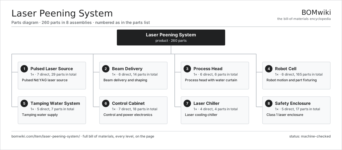
| # | Part | Qty | What it does |
|---|---|---|---|
| 1 | Pulsed Laser Source 7 parts | 1× | Pulsed Nd:YAG laser source |
| 2 | Beam Delivery 6 parts | 1× | Beam delivery and shaping |
| 3 | Process Head 6 parts | 1× | Process head with water curtain |
| 4 | Robot Cell 6 parts | 1× | Robot motion and part fixturing |
| 5 | Tamping Water System 5 parts | 1× | Tamping water supply |
| 6 | Control Cabinet 7 parts | 1× | Control and power electronics |
| 7 | Laser Chiller 4 parts | 1× | Laser cooling chiller |
| 8 | Safety Enclosure 5 parts | 1× | Class 1 laser enclosure |
3D model
No 3D model yet. Have a CAD file of this? Add a 3D model — STL renders right on this page; STEP, FreeCAD, and OpenSCAD sources are welcome too (openly licensed, like all 3D models on BOMwiki).
Build & assembly graph
expand / collapse · shared sub-assemblies converge · links to related products · est. labourTap an assembly to expand/collapse · tap a part to open it · use “Open page” for any node · drag to pan, scroll to zoom.
Bill of materials for Laser Peening System
8 top-level lines · 61 rows shown · 260 parts total · indented to 3 levels| # | Item / sub-assembly | Part no. | Qty/assy | Ext. qty | Parts | Type |
|---|---|---|---|---|---|---|
| 1 | Pulsed Laser Source 7 parts | laser-peening-system-laser-source | 1× | 1 | 29 | assembly |
| 1.1 | Nd:YAG Gain Rod | laser-peening-system-laser-rod | 4× | 4 | · | part |
| 1.2 | Xenon Flashlamp | laser-peening-system-flashlamp | 8× | 8 | · | part |
| 1.3 | Pockels Cell | laser-peening-system-pockels-cell | 1× | 1 | · | part |
| 1.4 | Resonator Mirror | laser-peening-system-resonator-mirror | 2× | 2 | · | part |
| 1.5 | Amplifier Stage 3 parts | laser-peening-system-amplifier-stage | 3× | 3 | 4 | assembly |
| 1.5.1 | Nd:YAG Gain Rod | laser-peening-system-laser-rod | 1× | 3 | · | part |
| 1.5.2 | Xenon Flashlamp | laser-peening-system-flashlamp | 2× | 6 | · | part |
| 1.5.3 | Flow Tube | laser-peening-system-flow-tube | 1× | 3 | · | part |
| 1.6 | Frequency Doubler | laser-peening-system-frequency-doubler | 1× | 1 | · | part |
| 1.7 | O-Ring Set | oring-set | 1× | 1 | · | part |
| 2 | Beam Delivery 6 parts | laser-peening-system-beam-delivery | 1× | 1 | 14 | assembly |
| 2.1 | Turning Mirror | laser-peening-system-turning-mirror | 6× | 6 | · | part |
| 2.2 | Beam Expander | laser-peening-system-beam-expander | 1× | 1 | · | part |
| 2.3 | Spatial Filter | laser-peening-system-spatial-filter | 1× | 1 | · | part |
| 2.4 | Focusing Lens | laser-peening-system-focusing-lens | 1× | 1 | · | part |
| 2.5 | Energy Monitor | laser-peening-system-energy-monitor | 1× | 1 | · | part |
| 2.6 | Beam Transport Tube | laser-peening-system-beam-tube | 4× | 4 | · | part |
| 3 | Process Head 6 parts | laser-peening-system-process-head | 1× | 1 | 6 | assembly |
| 3.1 | Water Curtain Nozzle | laser-peening-system-water-nozzle | 1× | 1 | · | part |
| 3.2 | Overlay Applicator | laser-peening-system-overlay-applicator | 1× | 1 | · | part |
| 3.3 | Protective Window | laser-peening-system-protective-window | 1× | 1 | · | part |
| 3.4 | Standoff Sensor | laser-peening-system-standoff-sensor | 1× | 1 | · | part |
| 3.5 | Shock Microphone | laser-peening-system-shock-mic | 1× | 1 | · | part |
| 3.6 | Fastener Set | fastener-set | 1× | 1 | · | part |
| 4 | Robot Cell 6 parts | laser-peening-system-robot-cell | 1× | 1 | 165 | assembly |
| 4.1 | Robot Arm | laser-peening-system-robot-arm | 1× | 1 | · | part |
| 4.2 | Servo Turntable | laser-peening-system-turntable | 1× | 1 | · | part |
| 4.3 | Part Fixture | laser-peening-system-part-fixture | 1× | 1 | · | part |
| 4.4 | Servo Motor 4 parts | servo-motor | 6× | 6 | 24 | assembly |
| 4.4.1 | Stator Assembly 3 parts + deeper › | stator-assembly | 1× | 6 | 3 | assembly |
| 4.4.2 | Rotor Assembly 4 parts + deeper › | rotor-assembly | 1× | 6 | 19 | assembly |
| 4.4.3 | Encoder | encoder | 1× | 6 | · | part |
| 4.4.4 | Motor Housing | motor-housing | 1× | 6 | · | part |
| 4.5 | Gearbox Housing | gearbox-housing | 6× | 6 | · | part |
| 4.6 | Ball Bearing | ball-bearing | 12× | 12 | · | part |
| 5 | Tamping Water System 5 parts | laser-peening-system-water-system | 1× | 1 | 7 | assembly |
| 5.1 | Water Pump | laser-peening-system-water-pump | 1× | 1 | · | part |
| 5.2 | Water Filter | laser-peening-system-water-filter | 2× | 2 | · | part |
| 5.3 | Recovery Tank | laser-peening-system-recovery-tank | 1× | 1 | · | part |
| 5.4 | Deionizer Cartridge | laser-peening-system-di-cartridge | 1× | 1 | · | part |
| 5.5 | Pressure Sensor | pressure-sensor | 2× | 2 | · | part |
| 6 | Control Cabinet 7 parts | laser-peening-system-control-cabinet | 1× | 1 | 18 | assembly |
| 6.1 | Capacitor Bank | laser-peening-system-capacitor-bank | 1× | 1 | · | part |
| 6.2 | Pulse-Forming Network | laser-peening-system-pfn | 1× | 1 | · | part |
| 6.3 | Cell PLC | laser-peening-system-plc | 1× | 1 | · | part |
| 6.4 | Power Supply | power-supply | 2× | 2 | · | part |
| 6.5 | Relay | relay | 8× | 8 | · | part |
| 6.6 | Bare PCB | pcb-bare | 4× | 4 | · | part |
| 6.7 | Wire Bundle | wire-bundle | 1× | 1 | · | part |
| 7 | Laser Chiller 4 parts | laser-peening-system-chiller | 1× | 1 | 4 | assembly |
| 7.1 | Refrigeration Compressor | laser-peening-system-compressor | 1× | 1 | · | part |
| 7.2 | Heat Exchanger | laser-peening-system-heat-exchanger | 1× | 1 | · | part |
| 7.3 | Coolant Pump | laser-peening-system-coolant-pump | 1× | 1 | · | part |
| 7.4 | Pressure Sensor | pressure-sensor | 1× | 1 | · | part |
| 8 | Safety Enclosure 5 parts | laser-peening-system-safety-enclosure | 1× | 1 | 17 | assembly |
| 8.1 | Sheet Metal Panel | sheet-panel | 8× | 8 | · | part |
| 8.2 | Interlock Switch | laser-peening-system-interlock-switch | 4× | 4 | · | part |
| 8.3 | Viewing Window | laser-peening-system-viewing-window | 2× | 2 | · | part |
| 8.4 | Warning Beacon | laser-peening-system-warning-beacon | 2× | 2 | · | part |
| 8.5 | Fastener Set | fastener-set | 1× | 1 | · | part |
Related products
same domain, ranked by shared parts Creep-Feed Grinder
571 parts · shares 4 with this page
Cut-to-Length Line
500 parts · shares 4 with this page
Drag Finishing Machine
735 parts · shares 4 with this page
Creep-Feed Grinder
571 parts · shares 4 with this page
Cut-to-Length Line
500 parts · shares 4 with this page
Drag Finishing Machine
735 parts · shares 4 with this page
 Flow Forming Machine
272 parts · shares 4 with this page
Forging Roll Machine
135 parts · shares 4 with this page
Flow Forming Machine
272 parts · shares 4 with this page
Forging Roll Machine
135 parts · shares 4 with this page
Sourcing: possible vendors
Prices, MOQ, and lead times are algorithmic estimates, not quotes, and not claims about these companies. Company mappings are curated by keyword; est. price band $10k–$1M. How estimates work| Vendor | HQ | Specialty | MOQ | Lead time |
|---|---|---|---|---|
|
🇩🇪DMG MORI
dmgmori.com ↗
|
Bielefeld, DE | Machine tools | 5 units | 12–20 wks |
|
🇯🇵Mazak
mazak.com ↗
|
Oguchi, JP | Machine tools | 5 units | 12–20 wks |
| haascnc.com ↗ | Oxnard, US | CNC machine tools | 5 units | 12–20 wks |
|
🇯🇵Okuma
okuma.com ↗
|
Niwa, JP | Machine tools | 5 units | 12–20 wks |
|
🇩🇪Trumpf
trumpf.com ↗
|
Ditzingen, DE | Laser & sheet-metal machines | 5 units | 12–20 wks |
1,044-word article