Bar Chamfering Machine
ProductOverview
A bar chamfering machine bevels the ends of metal bars and tubes so they are ready for the next operation. A raw bar comes off a saw with a square, often burred end. Before that bar can be threaded, pressed into a bore, welded, fed into a screw machine or simply handled safely, the sharp corner needs to be turned into a clean angled lead-in. This machine does that on both ends at once. It clamps the bar, runs a rotating cutter onto each end, cuts the bevel and ejects the finished piece, then loads the next bar from a magazine. A typical unit handles round bar from 6 to 60 mm in diameter and cuts a 45 degree chamfer up to about 5 mm deep, though the angle and depth are both adjustable.
The machine is laid out symmetrically around one horizontal axis. At the centre sits the Clamping Vise Unit holding the bar. To its left and right are the Left Chamfering Head and Right Chamfering Head, two spindle units that carry the cutters. Each head rides a Head Feed Slide that pushes it onto the bar end and pulls it back. The whole line sits on the Machine Bed, a welded base that holds the two heads on a common centreline, and the Bar Feed Unit supplies bars to the vise. A Control Cabinet sequences the cycle.
How it works
A cycle starts at the Bar Feed Unit. Bars sit in the Bar Magazine, a sloped rack, and roll down to the Bar Separator, which lets one bar through at a time so two never feed together. The Transfer Arm or a set of Feed Roller moves that bar to the vise centreline and pushes it lengthwise until it meets the Stock End Stop, which fixes how far each end projects.
The Clamping Vise Unit then grips the bar. Its Clamp Cylinder drives the moving Vise Jaw against a fixed one, and a Vee Location Block seats a round bar on its centreline so the chamfer comes out concentric. A Pressure Sensor confirms full clamp force before cutting starts, because a bar that slips under the cutter is scrapped and can break an insert. With the bar held, both feed slides advance their heads onto the two ends together. The spindles are already turning, so the inserts cut as the heads close in, reach the Depth Stop, dwell briefly to clean the bevel, then retract. The vise opens and the part drops to the conveyor. Doing both ends at once roughly halves the cycle compared with a single-end machine, which matters when a batch runs to thousands of bars.
The chamfering head and tooling
Each head is built around a Cutter Spindle running in Ball Bearing sets inside a Spindle Housing, sealed by an Oil Seal at each end against coolant. The Spindle Drive Motor drives the spindle through a Drive Belt and a Drive Pulley Set, and the pulley ratio sets the cutting speed; the Spindle Drive (VFD) in the cabinet trims it further so the surface speed suits the material.
The cutting is done by the Insert Cutter Head. Its Cutter Head Body is bored on the bar axis with insert pockets machined at the chamfer angle, and it holds several Carbide Chamfer Insert, indexable carbide tips clamped by a Insert Clamp Screw. When the head feeds onto the bar, the bar end enters the bore and the inserts shave the bevel as the head turns. Splitting the cut across several inserts spreads the load, gives a better finish and lets a worn edge be indexed or swapped in seconds. A Centring Pilot Bush at the centre of the head picks up the bar bore or face to keep the chamfer running true. Setting the chamfer angle means fitting a cutter head ground for that angle, and depth is set on the Depth Stop, so the same machine cuts 30, 45 or 60 degree chamfers by changing tooling.
Clamping and feed
Holding the bar still is half the job. The vise must take the full cutting thrust without letting the bar turn or walk, so the clamp force is hydraulic and held by an accumulator in the Hydraulic Power Pack through the whole cut. On thin-wall tube the jaws are smooth and the pressure is eased so the tube is not crushed; on solid bar serrated jaws bite harder.
Feed is the controlled approach of the head to the bar. On servo machines a Servo Motor turns a Ball Screw that moves the Slide Table along a Linear Guide Rail pair, with an Encoder reporting position so the slide can creep through the cut at a set feed rate and stop on the same depth every time. Simpler or heavier machines feed with a Feed Cylinder driven by the hydraulic pack against the fixed Depth Stop. Either way the Coolant & Swarf System floods the inserts: a Coolant Pump feeds aimed Coolant Nozzle that cool the carbide and wash chips off the cut, and a Swarf Conveyor clears the swarf from the tray into a bin.
Materials, variants and use
Cutting steel, stainless and brass bar all day puts the load on the carbide inserts and the spindle bearings, so those are the wear items watched in maintenance. The bar stock is whatever the downstream process needs: carbon and alloy steel for fasteners and shafts, stainless for fluid fittings, aluminium and brass for fittings and electrical parts. Variants range from single-end benchtop units up to twin-head automatic lines like this one with the Bar Feed Unit loading from a magazine. Some heads also face the end flat or roll a small radius in the same pass. The machines are used by fastener makers, tube and pipe fitting suppliers, hydraulic cylinder shops and any plant that feeds chamfered bar into automatic lathes, where a lead-in chamfer stops the bar jamming the collet. The cutting zone sits behind Guarding & Interlocks with interlocked doors so the spinning heads and flying chips stay enclosed while the machine runs.
Bar Chamfering Machine parts and their functions
10 top-level parts · 1,148 parts in total · full bill of materials below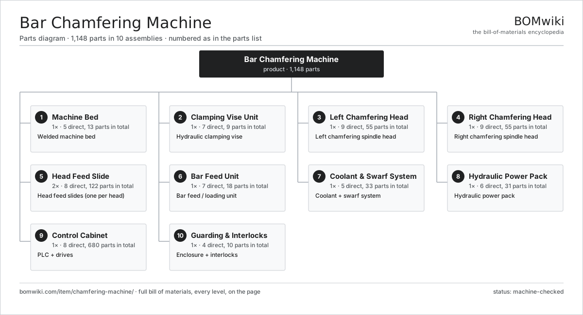
| # | Part | Qty | What it does |
|---|---|---|---|
| 1 | Machine Bed 5 parts | 1× | Welded machine bed |
| 2 | Clamping Vise Unit 7 parts | 1× | Hydraulic clamping vise |
| 3 | Left Chamfering Head 9 parts | 1× | Left chamfering spindle head |
| 4 | Right Chamfering Head 9 parts | 1× | Right chamfering spindle head |
| 5 | Head Feed Slide 8 parts | 2× | Head feed slides (one per head) |
| 6 | Bar Feed Unit 7 parts | 1× | Bar feed / loading unit |
| 7 | Coolant & Swarf System 5 parts | 1× | Coolant + swarf system |
| 8 | Hydraulic Power Pack 6 parts | 1× | Hydraulic power pack |
| 9 | Control Cabinet 8 parts | 1× | PLC + drives |
| 10 | Guarding & Interlocks 4 parts | 1× | Enclosure + interlocks |
3D model
No 3D model yet. Have a CAD file of this? Add a 3D model — STL renders right on this page; STEP, FreeCAD, and OpenSCAD sources are welcome too (openly licensed, like all 3D models on BOMwiki).
Build & assembly graph
expand / collapse · shared sub-assemblies converge · links to related products · est. labourTap an assembly to expand/collapse · tap a part to open it · use “Open page” for any node · drag to pan, scroll to zoom.
Bill of materials for Bar Chamfering Machine
10 top-level lines · 129 rows shown · 1,148 parts total · indented to 3 levels| # | Item / sub-assembly | Part no. | Qty/assy | Ext. qty | Parts | Type |
|---|---|---|---|---|---|---|
| 1 | Machine Bed 5 parts | chamfering-machine-bed | 1× | 1 | 13 | assembly |
| 1.1 | Bed Weldment | chamfering-machine-bed-weldment | 1× | 1 | · | part |
| 1.2 | Slide Way Rail | chamfering-machine-way-rail | 4× | 4 | · | part |
| 1.3 | Leveling Foot | chamfering-machine-leveling-foot | 6× | 6 | · | part |
| 1.4 | Chip Tray | chamfering-machine-chip-tray | 1× | 1 | · | part |
| 1.5 | Fastener Set | fastener-set | 1× | 1 | · | part |
| 2 | Clamping Vise Unit 7 parts | chamfering-machine-clamp-vise | 1× | 1 | 9 | assembly |
| 2.1 | Vise Body | chamfering-machine-vise-body | 1× | 1 | · | part |
| 2.2 | Vise Jaw | chamfering-machine-vise-jaw | 2× | 2 | · | part |
| 2.3 | Vee Location Block | chamfering-machine-vee-block | 2× | 2 | · | part |
| 2.4 | Clamp Cylinder | chamfering-machine-clamp-cylinder | 1× | 1 | · | part |
| 2.5 | Stock End Stop | chamfering-machine-stock-stop | 1× | 1 | · | part |
| 2.6 | Pressure Sensor | pressure-sensor | 1× | 1 | · | part |
| 2.7 | Fastener Set | fastener-set | 1× | 1 | · | part |
| 3 | Left Chamfering Head 9 parts | chamfering-machine-left-head | 1× | 1 | 55 | assembly |
| 3.1 | Cutter Spindle | chamfering-machine-spindle | 1× | 1 | · | part |
| 3.2 | Insert Cutter Head 4 parts | chamfering-machine-cutter-head | 1× | 1 | 14 | assembly |
| 3.2.1 | Cutter Head Body | chamfering-machine-cutter-body | 1× | 1 | · | part |
| 3.2.2 | Carbide Chamfer Insert | chamfering-machine-insert | 6× | 6 | · | part |
| 3.2.3 | Insert Clamp Screw | chamfering-machine-insert-screw | 6× | 6 | · | part |
| 3.2.4 | Centring Pilot Bush | chamfering-machine-pilot-bush | 1× | 1 | · | part |
| 3.3 | Carbide Chamfer Insert | chamfering-machine-insert | 6× | 6 | · | part |
| 3.4 | Spindle Housing | chamfering-machine-spindle-housing | 1× | 1 | · | part |
| 3.5 | Spindle Drive Motor 4 parts | chamfering-machine-spindle-motor | 1× | 1 | 25 | assembly |
| 3.5.1 | Stator Assembly 3 parts + deeper › | stator-assembly | 1× | 1 | 3 | assembly |
| 3.5.2 | Rotor Assembly 4 parts + deeper › | rotor-assembly | 1× | 1 | 19 | assembly |
| 3.5.3 | Motor Housing | chamfering-machine-motor-housing | 1× | 1 | · | part |
| 3.5.4 | Ball Bearing | ball-bearing | 2× | 2 | · | part |
| 3.6 | Drive Belt | drive-belt | 1× | 1 | · | part |
| 3.7 | Drive Pulley Set | chamfering-machine-pulley-set | 1× | 1 | · | part |
| 3.8 | Ball Bearing | ball-bearing | 4× | 4 | · | part |
| 3.9 | Oil Seal | oil-seal | 2× | 2 | · | part |
| 4 | Right Chamfering Head 9 parts | chamfering-machine-right-head | 1× | 1 | 55 | assembly |
| 4.1 | Cutter Spindle | chamfering-machine-spindle | 1× | 1 | · | part |
| 4.2 | Insert Cutter Head 4 parts | chamfering-machine-cutter-head | 1× | 1 | 14 | assembly |
| 4.2.1 | Cutter Head Body | chamfering-machine-cutter-body | 1× | 1 | · | part |
| 4.2.2 | Carbide Chamfer Insert | chamfering-machine-insert | 6× | 6 | · | part |
| 4.2.3 | Insert Clamp Screw | chamfering-machine-insert-screw | 6× | 6 | · | part |
| 4.2.4 | Centring Pilot Bush | chamfering-machine-pilot-bush | 1× | 1 | · | part |
| 4.3 | Carbide Chamfer Insert | chamfering-machine-insert | 6× | 6 | · | part |
| 4.4 | Spindle Housing | chamfering-machine-spindle-housing | 1× | 1 | · | part |
| 4.5 | Spindle Drive Motor 4 parts | chamfering-machine-spindle-motor | 1× | 1 | 25 | assembly |
| 4.5.1 | Stator Assembly 3 parts + deeper › | stator-assembly | 1× | 1 | 3 | assembly |
| 4.5.2 | Rotor Assembly 4 parts + deeper › | rotor-assembly | 1× | 1 | 19 | assembly |
| 4.5.3 | Motor Housing | chamfering-machine-motor-housing | 1× | 1 | · | part |
| 4.5.4 | Ball Bearing | ball-bearing | 2× | 2 | · | part |
| 4.6 | Drive Belt | drive-belt | 1× | 1 | · | part |
| 4.7 | Drive Pulley Set | chamfering-machine-pulley-set | 1× | 1 | · | part |
| 4.8 | Ball Bearing | ball-bearing | 4× | 4 | · | part |
| 4.9 | Oil Seal | oil-seal | 2× | 2 | · | part |
| 5 | Head Feed Slide 8 parts | chamfering-machine-feed-slide | 2× | 2 | 122 | assembly |
| 5.1 | Slide Table | chamfering-machine-slide-table | 1× | 2 | · | part |
| 5.2 | Linear Guide Rail | linear-guide | 2× | 4 | · | part |
| 5.3 | Ball Screw | ball-screw | 1× | 2 | · | part |
| 5.4 | Servo Motor 4 parts | servo-motor | 1× | 2 | 24 | assembly |
| 5.4.1 | Stator Assembly 3 parts + deeper › | stator-assembly | 1× | 2 | 3 | assembly |
| 5.4.2 | Rotor Assembly 4 parts + deeper › | rotor-assembly | 1× | 2 | 19 | assembly |
| 5.4.3 | Encoder | encoder | 1× | 2 | · | part |
| 5.4.4 | Motor Housing | motor-housing | 1× | 2 | · | part |
| 5.5 | Servo Drive 4 parts | servo-drive | 1× | 2 | 91 | assembly |
| 5.5.1 | Bare PCB | pcb-bare | 1× | 2 | · | part |
| 5.5.2 | IGBT Power Module | igbt-module | 1× | 2 | · | part |
| 5.5.3 | Gate Driver Board 3 parts + deeper › | gate-driver-board | 1× | 2 | 87 | assembly |
| 5.5.4 | DC-Link Capacitor | dc-link-cap | 2× | 4 | · | part |
| 5.6 | Encoder | encoder | 1× | 2 | · | part |
| 5.7 | Feed Cylinder | chamfering-machine-feed-cylinder | 1× | 2 | · | part |
| 5.8 | Depth Stop | chamfering-machine-depth-stop | 1× | 2 | · | part |
| 6 | Bar Feed Unit 7 parts | chamfering-machine-bar-feed | 1× | 1 | 18 | assembly |
| 6.1 | Bar Magazine | chamfering-machine-bar-magazine | 1× | 1 | · | part |
| 6.2 | Bar Separator | chamfering-machine-separator | 1× | 1 | · | part |
| 6.3 | Feed Roller | chamfering-machine-feed-roller | 4× | 4 | · | part |
| 6.4 | Transfer Arm | chamfering-machine-loader-arm | 1× | 1 | · | part |
| 6.5 | Helical Gear Pair | gear-pair | 1× | 1 | · | part |
| 6.6 | Pneumatic Cylinder | pneumatic-cylinder | 2× | 2 | · | part |
| 6.7 | Ball Bearing | ball-bearing | 8× | 8 | · | part |
| 7 | Coolant & Swarf System 5 parts | chamfering-machine-coolant-system | 1× | 1 | 33 | assembly |
| 7.1 | Coolant Tank | chamfering-machine-coolant-tank | 1× | 1 | · | part |
| 7.2 | Coolant Pump 5 parts | chamfering-machine-coolant-pump | 1× | 1 | 26 | assembly |
| 7.2.1 | Stator Assembly 3 parts + deeper › | stator-assembly | 1× | 1 | 3 | assembly |
| 7.2.2 | Rotor Assembly 4 parts + deeper › | rotor-assembly | 1× | 1 | 19 | assembly |
| 7.2.3 | Pump Housing | chamfering-machine-pump-housing | 1× | 1 | · | part |
| 7.2.4 | Oil Seal | oil-seal | 1× | 1 | · | part |
| 7.2.5 | Ball Bearing | ball-bearing | 2× | 2 | · | part |
| 7.3 | Coolant Nozzle | chamfering-machine-coolant-nozzle | 4× | 4 | · | part |
| 7.4 | Swarf Conveyor | chamfering-machine-swarf-conveyor | 1× | 1 | · | part |
| 7.5 | Filter Screen | chamfering-machine-filter-screen | 1× | 1 | · | part |
| 8 | Hydraulic Power Pack 6 parts | chamfering-machine-hydraulic-unit | 1× | 1 | 31 | assembly |
| 8.1 | Hydraulic Pump 5 parts | chamfering-machine-hyd-pump | 1× | 1 | 26 | assembly |
| 8.1.1 | Stator Assembly 3 parts + deeper › | stator-assembly | 1× | 1 | 3 | assembly |
| 8.1.2 | Rotor Assembly 4 parts + deeper › | rotor-assembly | 1× | 1 | 19 | assembly |
| 8.1.3 | Pump Housing | chamfering-machine-pump-housing | 1× | 1 | · | part |
| 8.1.4 | Oil Seal | oil-seal | 1× | 1 | · | part |
| 8.1.5 | Ball Bearing | ball-bearing | 2× | 2 | · | part |
| 8.2 | Oil Reservoir | chamfering-machine-hyd-tank | 1× | 1 | · | part |
| 8.3 | Valve Block | chamfering-machine-valve-block | 1× | 1 | · | part |
| 8.4 | Pressure Accumulator | chamfering-machine-accumulator | 1× | 1 | · | part |
| 8.5 | Pressure Sensor | pressure-sensor | 1× | 1 | · | part |
| 8.6 | O-Ring Set | oring-set | 1× | 1 | · | part |
| 9 | Control Cabinet 8 parts | chamfering-machine-control-cabinet | 1× | 1 | 680 | assembly |
| 9.1 | PLC Controller 4 parts | chamfering-machine-plc | 1× | 1 | 211 | assembly |
| 9.1.1 | Bare PCB | pcb-bare | 1× | 1 | · | part |
| 9.1.2 | Microcontroller | mcu | 2× | 2 | · | part |
| 9.1.3 | SMD Passive (R/C/L) | smd-passives | 180× | 180 | · | part |
| 9.1.4 | Connector | connector | 28× | 28 | · | part |
| 9.2 | Spindle Drive (VFD) 5 parts | chamfering-machine-vfd | 2× | 2 | 100 | assembly |
| 9.2.1 | Bare PCB | pcb-bare | 1× | 2 | · | part |
| 9.2.2 | Gate Driver IC | gate-driver-ic | 2× | 4 | · | part |
| 9.2.3 | Power MOSFET | mosfet | 6× | 12 | · | part |
| 9.2.4 | Power Inductor | power-inductor | 1× | 2 | · | part |
| 9.2.5 | SMD Passive (R/C/L) | smd-passives | 90× | 180 | · | part |
| 9.3 | Servo Drive 4 parts | servo-drive | 2× | 2 | 91 | assembly |
| 9.3.1 | Bare PCB | pcb-bare | 1× | 2 | · | part |
| 9.3.2 | IGBT Power Module | igbt-module | 1× | 2 | · | part |
| 9.3.3 | Gate Driver Board 3 parts + deeper › | gate-driver-board | 1× | 2 | 87 | assembly |
| 9.3.4 | DC-Link Capacitor | dc-link-cap | 2× | 4 | · | part |
| 9.4 | Power Supply | power-supply | 1× | 1 | · | part |
| 9.5 | Operator Panel 4 parts | chamfering-machine-hmi | 1× | 1 | 73 | assembly |
| 9.5.1 | LCD Panel | lcd-panel | 1× | 1 | · | part |
| 9.5.2 | Touch Digitizer | touch-digitizer | 1× | 1 | · | part |
| 9.5.3 | Bare PCB | pcb-bare | 1× | 1 | · | part |
| 9.5.4 | SMD Passive (R/C/L) | smd-passives | 70× | 70 | · | part |
| 9.6 | Relay | relay | 8× | 8 | · | part |
| 9.7 | Wire Bundle | wire-bundle | 1× | 1 | · | part |
| 9.8 | Sheet Metal Panel | sheet-panel | 4× | 4 | · | part |
| 10 | Guarding & Interlocks 4 parts | chamfering-machine-guarding | 1× | 1 | 10 | assembly |
| 10.1 | Sheet Metal Panel | sheet-panel | 4× | 4 | · | part |
| 10.2 | Polycarbonate Window | window-polycarbonate | 2× | 2 | · | part |
| 10.3 | Door Interlock Switch | chamfering-machine-door-interlock | 2× | 2 | · | part |
| 10.4 | Emergency Stop Button | chamfering-machine-estop | 2× | 2 | · | part |
Related products
same domain, ranked by shared parts Compression Spring Coiler
1,167 parts · shares 14 with this page
Compression Spring Coiler
1,167 parts · shares 14 with this page
 Torsion Spring Coiler
1,148 parts · shares 14 with this page
Torsion Spring Coiler
1,148 parts · shares 14 with this page
 CNC Milling Machine
400 parts · shares 11 with this page
CNC Milling Machine
400 parts · shares 11 with this page
Sourcing: possible vendors
Prices, MOQ, and lead times are algorithmic estimates, not quotes, and not claims about these companies. Company mappings are curated by keyword; est. price band $10k–$1M. How estimates work| Vendor | HQ | Specialty | MOQ | Lead time |
|---|---|---|---|---|
|
🇩🇪DMG MORI
dmgmori.com ↗
|
Bielefeld, DE | Machine tools | 5 units | 12–20 wks |
|
🇯🇵Mazak
mazak.com ↗
|
Oguchi, JP | Machine tools | 5 units | 12–20 wks |
| haascnc.com ↗ | Oxnard, US | CNC machine tools | 5 units | 12–20 wks |
|
🇯🇵Okuma
okuma.com ↗
|
Niwa, JP | Machine tools | 5 units | 12–20 wks |
|
🇩🇪Trumpf
trumpf.com ↗
|
Ditzingen, DE | Laser & sheet-metal machines | 5 units | 12–20 wks |
1,066-word article