Crankshaft Grinder
ProductOverview
A crankshaft grinder finishes the bearing surfaces of an engine crankshaft to final size, roundness, and surface finish after the forging or casting has been turned, heat-treated, and roughed. A crankshaft has two families of journals: the main journals, which sit on the engine block centerline, and the rod or pin journals, which carry the connecting rods and are offset from that centerline by the crank throw. Both must be ground concentric, round, and parallel within a few microns, because clearance in a plain bearing is set by the journal diameter. This machine grinds both families on one setup using a Wheelhead & Spindle carrying an electroplated CBN Grinding Wheel, a work drive in the Work-Drive Headstock, and an in-process In-Process Diameter Gauge that ends each cut at the target diameter.
Everything mounts on the Machine Bed & Ways, a mineral-cast bed chosen for its damping and thermal stability. The crank is held between the headstock and the Footstock, supported along its length by Steady Rest units, and the wheel is fed in by the Wheelhead & Spindle under CNC Control.
How it works
For a main journal the crank turns on its own main-bearing axis. The flange end is gripped by the Work Faceplate, a Driving Dog transmits rotation, and the free end runs on the Live Center in the footstock. The Work-Drive Headstock rotates the work slowly while the wheel, spinning at 60 to 120 metres per second, is fed in by the X Infeed Slide. The slide uses a Ball Screw on Linear Guide Rail rails driven by a Servo Motor, with a X-Axis Glass Scale reporting position to 0.1 micron. As material comes off, the In-Process Diameter Gauge rides the shrinking journal and tells the control the instant size is reached, so the cut stops on diameter rather than on a programmed depth.
Pin journals are harder, because each one orbits the main axis at the crank throw radius. Two methods exist. On the older eccentric method the Crank-Pin Chuck uses an Eccentric Setting Plate to shift the work center sideways by the throw, so the chosen pin journal turns on the spindle axis and is ground exactly like a main; a Balance Counterweight cancels the resulting imbalance. On a modern CNC machine the crank stays on its main axis and the wheelhead chases the orbiting pin: the C-Axis Encoder reports crank angle and the CNC Control interpolates X infeed against the C axis so the wheel oscillates in and out in step with the pin orbit. This follow or orbital grinding removes the need to re-clamp for each pin and keeps indexing between pins accurate.
Wheelhead and spindle
The cutting edge of the machine is the Wheel Spindle Cartridge, a precision cartridge holding the wheel arbor on angular-contact Ball Bearing sets sealed by Oil Seal elements. The CBN Grinding Wheel runs cooler and far longer than a vitrified wheel on hardened journal steel, which is why it is standard on this class of machine. Wheel unbalance at these speeds prints straight onto the roundness of the journal, so a Auto Wheel Balancer with in-spindle balance heads trims residual unbalance while the wheel turns. The Wheel Spindle Motor drives the spindle through a Drive Belt.
Wheel dressing
A CBN wheel needs truing to keep its face round and its profile correct. The CBN Wheel Dresser feeds a powered Rotary Diamond Disc across the wheel on its own slide. Because CBN is expensive and slow-wearing, dressing removes only a few microns at a time and is scheduled by part count rather than by every cycle. The dresser slide shares the same Ball Screw and Linear Guide Rail hardware family as the infeed slide, which keeps spare parts common across the machine.
Workholding and support
A crankshaft is long, slender, and out of balance, so support matters as much as drive. The Footstock advances its Footstock Quill hydraulically to clamp the crank between centers at a controlled force. Along the span, Steady Rest rests close their Support Shoe elements onto the journal under spring and hydraulic load, holding it against the wheel so it cannot deflect or chatter. The shoes are bronze or carbide and ride directly on the finished surface, so coolant must be clean where they contact.
Coolant and thermal control
Grinding puts most of its energy into heat, and heat distorts the very geometry the machine exists to hold. The High-Pressure Coolant System system floods the grind zone through Coherent-Jet Nozzle jets aimed tangent to the wheel, then filters and recirculates the oil. A Coolant Chiller holds the coolant at a fixed temperature so the bed and work do not grow during a shift. Clean coolant also protects the journal surface from scratches and keeps the steady shoes from picking up swarf.
Control and variants
The CNC Control coordinates the X infeed servo, the C-axis work drive, the gauge, the dresser, and the coolant. Its core job on pin journals is the tight X-C interpolation that traces the orbit. Machines of this kind range from single-wheel general-purpose grinders found in engine rebuild shops to multi-wheel production grinders in engine plants that grind several journals at once. The bed, headstock, wheelhead, and gauge described here are common to both; production machines add wheel slides and automation, while a rebuild-shop machine keeps one wheel and relies more on the operator and the In-Process Diameter Gauge to hold size across a wide mix of cranks.
Crankshaft Grinder parts and their functions
11 top-level parts · 511 parts in total · full bill of materials below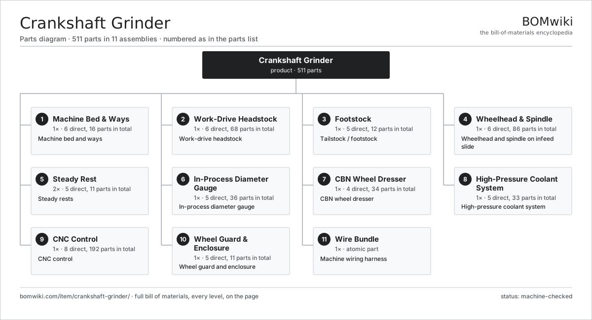
| # | Part | Qty | What it does |
|---|---|---|---|
| 1 | Machine Bed & Ways 6 parts | 1× | Machine bed and ways |
| 2 | Work-Drive Headstock 6 parts | 1× | Work-drive headstock |
| 3 | Footstock 5 parts | 1× | Tailstock / footstock |
| 4 | Wheelhead & Spindle 6 parts | 1× | Wheelhead and spindle on infeed slide |
| 5 | Steady Rest 5 parts | 2× | Steady rests |
| 6 | In-Process Diameter Gauge 5 parts | 1× | In-process diameter gauge |
| 7 | CBN Wheel Dresser 4 parts | 1× | CBN wheel dresser |
| 8 | High-Pressure Coolant System 5 parts | 1× | High-pressure coolant system |
| 9 | CNC Control 8 parts | 1× | CNC control |
| 10 | Wheel Guard & Enclosure 5 parts | 1× | Wheel guard and enclosure |
| 11 | Wire Bundle | 1× | Machine wiring harness |
3D model
No 3D model yet. Have a CAD file of this? Add a 3D model — STL renders right on this page; STEP, FreeCAD, and OpenSCAD sources are welcome too (openly licensed, like all 3D models on BOMwiki).
Build & assembly graph
expand / collapse · shared sub-assemblies converge · links to related products · est. labourTap an assembly to expand/collapse · tap a part to open it · use “Open page” for any node · drag to pan, scroll to zoom.
Bill of materials for Crankshaft Grinder
11 top-level lines · 146 rows shown · 511 parts total · indented to 3 levels| # | Item / sub-assembly | Part no. | Qty/assy | Ext. qty | Parts | Type |
|---|---|---|---|---|---|---|
| 1 | Machine Bed & Ways 6 parts | crankshaft-grinder-bed | 1× | 1 | 16 | assembly |
| 1.1 | Bed Casting | crankshaft-grinder-bed-casting | 1× | 1 | · | part |
| 1.2 | Longitudinal (Z) Way | crankshaft-grinder-z-way | 2× | 2 | · | part |
| 1.3 | Wheelhead (X) Way | crankshaft-grinder-x-way | 2× | 2 | · | part |
| 1.4 | Telescopic Way Cover | crankshaft-grinder-way-cover | 4× | 4 | · | part |
| 1.5 | Leveling Foot | crankshaft-grinder-leveling-foot | 6× | 6 | · | part |
| 1.6 | Fastener Set | fastener-set | 1× | 1 | · | part |
| 2 | Work-Drive Headstock 6 parts | crankshaft-grinder-headstock | 1× | 1 | 68 | assembly |
| 2.1 | Headstock Drive Motor 5 parts | crankshaft-grinder-hs-motor | 1× | 1 | 26 | assembly |
| 2.1.1 | Stator Assembly 3 parts + deeper › | stator-assembly | 1× | 1 | 3 | assembly |
| 2.1.2 | Rotor Assembly 4 parts + deeper › | rotor-assembly | 1× | 1 | 19 | assembly |
| 2.1.3 | Copper Winding | copper-winding | 1× | 1 | · | part |
| 2.1.4 | Motor Housing | motor-housing | 1× | 1 | · | part |
| 2.1.5 | Ball Bearing | ball-bearing | 2× | 2 | · | part |
| 2.2 | Headstock Spindle 4 parts | crankshaft-grinder-hs-spindle | 1× | 1 | 8 | assembly |
| 2.2.1 | Ball Bearing | ball-bearing | 4× | 4 | · | part |
| 2.2.2 | Oil Seal | oil-seal | 2× | 2 | · | part |
| 2.2.3 | Spindle Shaft | crankshaft-grinder-hs-shaft | 1× | 1 | · | part |
| 2.2.4 | Helical Gear Pair | gear-pair | 1× | 1 | · | part |
| 2.3 | Work Faceplate | crankshaft-grinder-faceplate | 1× | 1 | · | part |
| 2.4 | Crank-Pin Chuck 4 parts | crankshaft-grinder-pin-chuck | 1× | 1 | 8 | assembly |
| 2.4.1 | Eccentric Setting Plate | crankshaft-grinder-eccentric-plate | 1× | 1 | · | part |
| 2.4.2 | Clamp Jaw | crankshaft-grinder-clamp-jaw | 4× | 4 | · | part |
| 2.4.3 | Balance Counterweight | crankshaft-grinder-counterweight | 2× | 2 | · | part |
| 2.4.4 | Fastener Set | fastener-set | 1× | 1 | · | part |
| 2.5 | Driving Dog | crankshaft-grinder-driver-dog | 1× | 1 | · | part |
| 2.6 | C-Axis Encoder 4 parts | crankshaft-grinder-c-encoder | 1× | 1 | 24 | assembly |
| 2.6.1 | Bare PCB | pcb-bare | 1× | 1 | · | part |
| 2.6.2 | Microcontroller | mcu | 1× | 1 | · | part |
| 2.6.3 | SMD Passive (R/C/L) | smd-passives | 20× | 20 | · | part |
| 2.6.4 | Connector | connector | 2× | 2 | · | part |
| 3 | Footstock 5 parts | crankshaft-grinder-footstock | 1× | 1 | 12 | assembly |
| 3.1 | Footstock Body | crankshaft-grinder-fs-body | 1× | 1 | · | part |
| 3.2 | Footstock Quill | crankshaft-grinder-fs-quill | 1× | 1 | · | part |
| 3.3 | Live Center 3 parts | crankshaft-grinder-live-center | 1× | 1 | 4 | assembly |
| 3.3.1 | Ball Bearing | ball-bearing | 2× | 2 | · | part |
| 3.3.2 | 60° Center Point | crankshaft-grinder-center-point | 1× | 1 | · | part |
| 3.3.3 | Oil Seal | oil-seal | 1× | 1 | · | part |
| 3.4 | Quill Clamp Cylinder 3 parts | crankshaft-grinder-fs-cylinder | 1× | 1 | 4 | assembly |
| 3.4.1 | O-Ring Set | oring-set | 1× | 1 | · | part |
| 3.4.2 | Oil Seal | oil-seal | 2× | 2 | · | part |
| 3.4.3 | Clamp Piston & Rod | crankshaft-grinder-fs-piston | 1× | 1 | · | part |
| 3.5 | Ball Bearing | ball-bearing | 2× | 2 | · | part |
| 4 | Wheelhead & Spindle 6 parts | crankshaft-grinder-wheelhead | 1× | 1 | 86 | assembly |
| 4.1 | X Infeed Slide 5 parts | crankshaft-grinder-wh-slide | 1× | 1 | 30 | assembly |
| 4.1.1 | Ball Screw | ball-screw | 1× | 1 | · | part |
| 4.1.2 | Linear Guide Rail | linear-guide | 2× | 2 | · | part |
| 4.1.3 | Servo Motor 4 parts + deeper › | servo-motor | 1× | 1 | 24 | assembly |
| 4.1.4 | Ball Bearing | ball-bearing | 2× | 2 | · | part |
| 4.1.5 | X-Axis Glass Scale | crankshaft-grinder-x-scale | 1× | 1 | · | part |
| 4.2 | Wheel Spindle Cartridge 4 parts | crankshaft-grinder-wh-spindle | 1× | 1 | 8 | assembly |
| 4.2.1 | Ball Bearing | ball-bearing | 4× | 4 | · | part |
| 4.2.2 | Oil Seal | oil-seal | 2× | 2 | · | part |
| 4.2.3 | Wheel Arbor | crankshaft-grinder-wh-arbor | 1× | 1 | · | part |
| 4.2.4 | Spindle Housing | crankshaft-grinder-wh-housing | 1× | 1 | · | part |
| 4.3 | CBN Grinding Wheel | crankshaft-grinder-cbn-wheel | 1× | 1 | · | part |
| 4.4 | Wheel Flange | crankshaft-grinder-wheel-flange | 2× | 2 | · | part |
| 4.5 | Wheel Spindle Motor 6 parts | crankshaft-grinder-wh-motor | 1× | 1 | 27 | assembly |
| 4.5.1 | Stator Assembly 3 parts + deeper › | stator-assembly | 1× | 1 | 3 | assembly |
| 4.5.2 | Rotor Assembly 4 parts + deeper › | rotor-assembly | 1× | 1 | 19 | assembly |
| 4.5.3 | Copper Winding | copper-winding | 1× | 1 | · | part |
| 4.5.4 | Motor Housing | motor-housing | 1× | 1 | · | part |
| 4.5.5 | Ball Bearing | ball-bearing | 2× | 2 | · | part |
| 4.5.6 | Drive Belt | drive-belt | 1× | 1 | · | part |
| 4.6 | Auto Wheel Balancer 4 parts | crankshaft-grinder-balancer | 1× | 1 | 18 | assembly |
| 4.6.1 | Bare PCB | pcb-bare | 1× | 1 | · | part |
| 4.6.2 | Microcontroller | mcu | 1× | 1 | · | part |
| 4.6.3 | SMD Passive (R/C/L) | smd-passives | 15× | 15 | · | part |
| 4.6.4 | Balance Head | crankshaft-grinder-balance-head | 1× | 1 | · | part |
| 5 | Steady Rest 5 parts | crankshaft-grinder-steady | 2× | 2 | 11 | assembly |
| 5.1 | Steady Rest Body | crankshaft-grinder-steady-body | 1× | 2 | · | part |
| 5.2 | Support Shoe | crankshaft-grinder-steady-shoe | 3× | 6 | · | part |
| 5.3 | Shoe Clamp Cylinder 3 parts | crankshaft-grinder-steady-cylinder | 1× | 2 | 4 | assembly |
| 5.3.1 | O-Ring Set | oring-set | 1× | 2 | · | part |
| 5.3.2 | Oil Seal | oil-seal | 2× | 4 | · | part |
| 5.3.3 | Shoe Piston | crankshaft-grinder-steady-piston | 1× | 2 | · | part |
| 5.4 | Coil Spring | coil-spring | 2× | 4 | · | part |
| 5.5 | O-Ring Set | oring-set | 1× | 2 | · | part |
| 6 | In-Process Diameter Gauge 5 parts | crankshaft-grinder-gauge | 1× | 1 | 36 | assembly |
| 6.1 | Gauge Head | crankshaft-grinder-gauge-head | 1× | 1 | · | part |
| 6.2 | Measuring Finger | crankshaft-grinder-gauge-finger | 2× | 2 | · | part |
| 6.3 | Retract Arm 2 parts | crankshaft-grinder-gauge-arm | 1× | 1 | 2 | assembly |
| 6.3.1 | Arm Actuator | crankshaft-grinder-gauge-actuator | 1× | 1 | · | part |
| 6.3.2 | O-Ring Set | oring-set | 1× | 1 | · | part |
| 6.4 | Gauge Amplifier Board 4 parts | crankshaft-grinder-gauge-board | 1× | 1 | 30 | assembly |
| 6.4.1 | Bare PCB | pcb-bare | 1× | 1 | · | part |
| 6.4.2 | Microcontroller | mcu | 1× | 1 | · | part |
| 6.4.3 | SMD Passive (R/C/L) | smd-passives | 25× | 25 | · | part |
| 6.4.4 | Connector | connector | 3× | 3 | · | part |
| 6.5 | Pressure Sensor | pressure-sensor | 1× | 1 | · | part |
| 7 | CBN Wheel Dresser 4 parts | crankshaft-grinder-dresser | 1× | 1 | 34 | assembly |
| 7.1 | Dresser Slide 3 parts | crankshaft-grinder-dresser-slide | 1× | 1 | 5 | assembly |
| 7.1.1 | Ball Screw | ball-screw | 1× | 1 | · | part |
| 7.1.2 | Linear Guide Rail | linear-guide | 2× | 2 | · | part |
| 7.1.3 | Ball Bearing | ball-bearing | 2× | 2 | · | part |
| 7.2 | Dressing Spindle 3 parts | crankshaft-grinder-dress-spindle | 1× | 1 | 4 | assembly |
| 7.2.1 | Ball Bearing | ball-bearing | 2× | 2 | · | part |
| 7.2.2 | Oil Seal | oil-seal | 1× | 1 | · | part |
| 7.2.3 | Dressing Spindle Shaft | crankshaft-grinder-dress-shaft | 1× | 1 | · | part |
| 7.3 | Rotary Diamond Disc | crankshaft-grinder-diamond-disc | 1× | 1 | · | part |
| 7.4 | Servo Motor 4 parts | servo-motor | 1× | 1 | 24 | assembly |
| 7.4.1 | Stator Assembly 3 parts + deeper › | stator-assembly | 1× | 1 | 3 | assembly |
| 7.4.2 | Rotor Assembly 4 parts + deeper › | rotor-assembly | 1× | 1 | 19 | assembly |
| 7.4.3 | Encoder | encoder | 1× | 1 | · | part |
| 7.4.4 | Motor Housing | motor-housing | 1× | 1 | · | part |
| 8 | High-Pressure Coolant System 5 parts | crankshaft-grinder-coolant | 1× | 1 | 33 | assembly |
| 8.1 | Coolant Pump 4 parts | crankshaft-grinder-coolant-pump | 1× | 1 | 24 | assembly |
| 8.1.1 | Stator Assembly 3 parts + deeper › | stator-assembly | 1× | 1 | 3 | assembly |
| 8.1.2 | Rotor Assembly 4 parts + deeper › | rotor-assembly | 1× | 1 | 19 | assembly |
| 8.1.3 | Motor Housing | motor-housing | 1× | 1 | · | part |
| 8.1.4 | Oil Seal | oil-seal | 1× | 1 | · | part |
| 8.2 | Coolant Tank | crankshaft-grinder-coolant-tank | 1× | 1 | · | part |
| 8.3 | Coherent-Jet Nozzle | crankshaft-grinder-coolant-nozzle | 2× | 2 | · | part |
| 8.4 | Cartridge Filter | crankshaft-grinder-coolant-filter | 1× | 1 | · | part |
| 8.5 | Coolant Chiller 4 parts | crankshaft-grinder-chiller | 1× | 1 | 5 | assembly |
| 8.5.1 | Heating Element | heating-element | 1× | 1 | · | part |
| 8.5.2 | Pressure Sensor | pressure-sensor | 1× | 1 | · | part |
| 8.5.3 | Relay | relay | 2× | 2 | · | part |
| 8.5.4 | Refrigerant Coil | crankshaft-grinder-chiller-coil | 1× | 1 | · | part |
| 9 | CNC Control 8 parts | crankshaft-grinder-control | 1× | 1 | 192 | assembly |
| 9.1 | CNC Motherboard 3 parts | crankshaft-grinder-cnc-board | 1× | 1 | 83 | assembly |
| 9.1.1 | Bare PCB | pcb-bare | 1× | 1 | · | part |
| 9.1.2 | Microcontroller | mcu | 2× | 2 | · | part |
| 9.1.3 | SMD Passive (R/C/L) | smd-passives | 80× | 80 | · | part |
| 9.2 | X-Axis Servo Drive 4 parts | crankshaft-grinder-x-drive | 1× | 1 | 43 | assembly |
| 9.2.1 | Bare PCB | pcb-bare | 1× | 1 | · | part |
| 9.2.2 | Microcontroller | mcu | 1× | 1 | · | part |
| 9.2.3 | SMD Passive (R/C/L) | smd-passives | 40× | 40 | · | part |
| 9.2.4 | Relay | relay | 1× | 1 | · | part |
| 9.3 | C-Axis Servo Drive 4 parts | crankshaft-grinder-c-drive | 1× | 1 | 43 | assembly |
| 9.3.1 | Bare PCB | pcb-bare | 1× | 1 | · | part |
| 9.3.2 | Microcontroller | mcu | 1× | 1 | · | part |
| 9.3.3 | SMD Passive (R/C/L) | smd-passives | 40× | 40 | · | part |
| 9.3.4 | Relay | relay | 1× | 1 | · | part |
| 9.4 | LCD Panel | lcd-panel | 1× | 1 | · | part |
| 9.5 | Power Supply | power-supply | 1× | 1 | · | part |
| 9.6 | Relay | relay | 8× | 8 | · | part |
| 9.7 | Connector | connector | 12× | 12 | · | part |
| 9.8 | Electrical Cabinet | crankshaft-grinder-cabinet | 1× | 1 | · | part |
| 10 | Wheel Guard & Enclosure 5 parts | crankshaft-grinder-guard | 1× | 1 | 11 | assembly |
| 10.1 | Wheel Guard | crankshaft-grinder-wheel-guard | 1× | 1 | · | part |
| 10.2 | Machine Enclosure | crankshaft-grinder-enclosure | 1× | 1 | · | part |
| 10.3 | Sheet Metal Panel | sheet-panel | 6× | 6 | · | part |
| 10.4 | Sliding Door | crankshaft-grinder-door | 2× | 2 | · | part |
| 10.5 | Fastener Set | fastener-set | 1× | 1 | · | part |
| 11 | Wire Bundle | wire-bundle | 1× | 1 | · | part |
Related products
same domain, ranked by shared parts Rotary-Table Surface Grinder
172 parts · shares 10 with this page
Camshaft Grinder
489 parts · shares 9 with this page
Rotary-Table Surface Grinder
172 parts · shares 10 with this page
Camshaft Grinder
489 parts · shares 9 with this page
 Profile Grinding Machine
815 parts · shares 7 with this page
Profile Grinding Machine
815 parts · shares 7 with this page
 Heat Treatment Furnace
299 parts · shares 7 with this page
Heat Treatment Furnace
299 parts · shares 7 with this page
 Nitriding Furnace
105 parts · shares 6 with this page
Nitriding Furnace
105 parts · shares 6 with this page
 Continuous Belt Furnace
130 parts · shares 6 with this page
Continuous Belt Furnace
130 parts · shares 6 with this page
Sourcing: possible vendors
Prices, MOQ, and lead times are algorithmic estimates, not quotes, and not claims about these companies. Company mappings are curated by keyword; est. price band $10k–$1M. How estimates work| Vendor | HQ | Specialty | MOQ | Lead time |
|---|---|---|---|---|
|
🇩🇪DMG MORI
dmgmori.com ↗
|
Bielefeld, DE | Machine tools | 5 units | 12–20 wks |
|
🇯🇵Mazak
mazak.com ↗
|
Oguchi, JP | Machine tools | 5 units | 12–20 wks |
| haascnc.com ↗ | Oxnard, US | CNC machine tools | 5 units | 12–20 wks |
|
🇯🇵Okuma
okuma.com ↗
|
Niwa, JP | Machine tools | 5 units | 12–20 wks |
|
🇩🇪Trumpf
trumpf.com ↗
|
Ditzingen, DE | Laser & sheet-metal machines | 5 units | 12–20 wks |
956-word article