Roller Leveler
ProductOverview
A roller leveler removes coil set, wavy edge and other shape defects from metal sheet by flexing it back and forth through a row of staggered rolls. The strip enters with a built-in curvature from being wound in a coil and leaves flat. The machine works by bending: the Leveling Roll Cassette forces the strip into a series of alternating up and down arcs whose curvature is sharp enough near the entry to drive the surface fibers past their elastic limit. Each successive roll uses a slightly gentler bend, so the residual curvature is reduced step by step until the strip relaxes to nearly straight when it leaves the last roll.
This is the key difference between a roller leveler and a strip tension leveler. A roller leveler only flexes the strip, it does not pull on it. A tension leveler stretches the whole strip past yield under high longitudinal tension and so can correct internal length differences across the width, such as center buckle and quarter buckle, that a roller leveler cannot fully remove. A roller leveler is simpler, cheaper and well suited to plate, structural sheet and thicker gauges where coil set and cross-bow are the main problems and the flatness target is moderate.
How it works
The strip threads between two banks of small-diameter work rolls. The lower bank sits in a fixed frame and the upper bank sits in a frame that can be lowered toward it. When the upper rolls are lowered so that they reach down past the plane of the lower rolls, the strip is forced to weave between them. The depth of this overlap is called intermesh or penetration, and it sets how sharply the strip is bent at each roll. Because the work rolls are small, the bend radius is short and the strip yields at a modest roll-separating force.
The first rolls use the deepest intermesh to put a large reversing strain into the strip and erase the memory of the coil. The intermesh is then reduced toward the exit so the last bends are shallow and the strip comes off straight rather than over-bent in the opposite direction. This taper from entry to exit is set by tilting the upper frame using the Frame Tilt Screw screws while the overall depth is set by the Intermesh and Parallelism Adjustment wedges and cylinders.
Entry and exit
The coil is loaded by the Coil Loading Car onto the Expanding Mandrel of the Uncoiler, which pays the strip off against the drag of the Uncoiler Drag Brake so the strip stays taut. The Strip Edge Guide keeps the strip centered with feedback from its Edge Position Sensor, and the Entry Pinch Roll Unit grips the strip and pushes it squarely into the first work roll. On the far side the Exit Pinch Roll Unit pulls the flattened strip out of the cassette and the Exit Flattener gives it a final low-curvature pass to take out any residual curl before the strip reaches the Exit Support Table or a downstream shear.
Leveling roll cassette
The Leveling Roll Cassette is the working core. It carries the Leveling Work Roll rolls, split between the Upper Work Roll Bank and the Lower Work Roll Bank, with the upper rolls staggered half a pitch from the lower ones so the strip is bent first one way and then the other. Small work rolls bend the strip sharply but would deflect under the bending load, so each is braced by a row of Backup Roll rolls. Under each backup row sits an adjustable Flexor Roll that can bow the work roll slightly along its length; bowing the rolls puts more bend into the center or the edges of the strip and so corrects cross-bow and edge wave across the width. Each roll end runs in a Roll Journal Block, and the whole cassette lifts out on the Cassette Change Cradle for roll changes between products.
Drive
All the work rolls must turn at the same surface speed so they carry the strip through without scuffing its faces. The Main Gearmotor feeds the Distribution Gearbox, a gearbox with one output per roll, and each output drives a roll through a Drive Spindle spindle fitted with Universal Joint joints at both ends. The joints let the spindle keep driving the roll while the upper frame moves up and down for intermesh changes, since the angle between gearbox and roll shifts as the gap changes.
Lubrication and hydraulics
The Roll Lubrication and Coolant Circuit circuit keeps an oil film between the work rolls and their backups and washes fines off the roll faces so the strip surface is not marked; the Lubrication Pump circulates oil through the Spray Bar bars and back through the Coolant Filter. The Hydraulic Power Unit supplies the higher-pressure oil that drives the Intermesh Cylinder cylinders, lifts the upper frame for roll changes and expands the uncoiler mandrel. A Axial Piston Pump feeds the Valve Manifold of Proportional Valve valves, with an Bladder Accumulator for fast response and an Oil Cooler holding the oil temperature.
Control and structure
The Control System runs the setup logic on the Line PLC, holding the intermesh depth, the entry-to-exit taper and the line speed against the Roll Gap Transducer feedback so that a stored recipe is repeated coil to coil. The operator selects products through the Operator HMI. The roll-separating force can be large on heavy gauges, so the cassette sits in the Machine Frame, whose Roll Stand Housing castings and heavy Base Frame hold the upper and lower banks in alignment over long runs.
Materials and variants
Work rolls are tool steel hardened to around 60 HRC because they take millions of high-stress bending cycles, while backup and flattener rolls use bearing steel for wear life. Light levelers for thin sheet use many small rolls at a fine pitch to reach a flat result, while heavy plate levelers use fewer, larger rolls at a wide pitch and the highest roll-separating force. Many roller levelers run inline ahead of a cut-to-length shear or a blanking press, where the uncoiler and exit table are replaced by the feed sections of the host line; others run as standalone units flattening pre-cut sheets fed by hand or by a sheet feeder.
Roller Leveler parts and their functions
9 top-level parts · 469 parts in total · full bill of materials below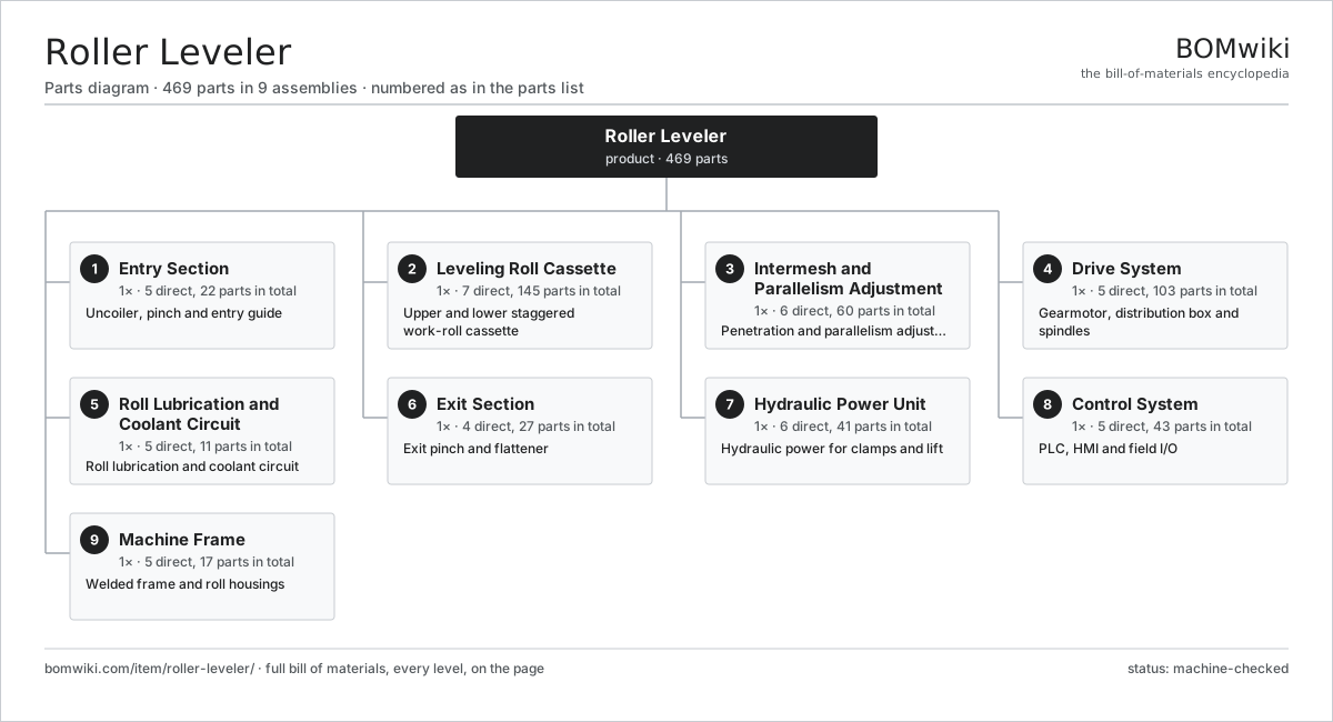
| # | Part | Qty | What it does |
|---|---|---|---|
| 1 | Entry Section 5 parts | 1× | Uncoiler, pinch and entry guide |
| 2 | Leveling Roll Cassette 7 parts | 1× | Upper and lower staggered work-roll cassette |
| 3 | Intermesh and Parallelism Adjustment 6 parts | 1× | Penetration and parallelism adjustment |
| 4 | Drive System 5 parts | 1× | Gearmotor, distribution box and spindles |
| 5 | Roll Lubrication and Coolant Circuit 5 parts | 1× | Roll lubrication and coolant circuit |
| 6 | Exit Section 4 parts | 1× | Exit pinch and flattener |
| 7 | Hydraulic Power Unit 6 parts | 1× | Hydraulic power for clamps and lift |
| 8 | Control System 5 parts | 1× | PLC, HMI and field I/O |
| 9 | Machine Frame 5 parts | 1× | Welded frame and roll housings |
3D model
No 3D model yet. Have a CAD file of this? Add a 3D model — STL renders right on this page; STEP, FreeCAD, and OpenSCAD sources are welcome too (openly licensed, like all 3D models on BOMwiki).
Build & assembly graph
expand / collapse · shared sub-assemblies converge · links to related products · est. labourTap an assembly to expand/collapse · tap a part to open it · use “Open page” for any node · drag to pan, scroll to zoom.
Bill of materials for Roller Leveler
9 top-level lines · 115 rows shown · 469 parts total · indented to 3 levels| # | Item / sub-assembly | Part no. | Qty/assy | Ext. qty | Parts | Type |
|---|---|---|---|---|---|---|
| 1 | Entry Section 5 parts | roller-leveler-entry-section | 1× | 1 | 22 | assembly |
| 1.1 | Uncoiler 5 parts | roller-leveler-uncoiler | 1× | 1 | 6 | assembly |
| 1.1.1 | Expanding Mandrel | roller-leveler-mandrel | 1× | 1 | · | part |
| 1.1.2 | Mandrel Expansion Cylinder | roller-leveler-mandrel-cylinder | 1× | 1 | · | part |
| 1.1.3 | Uncoiler Drag Brake | roller-leveler-uncoiler-brake | 1× | 1 | · | part |
| 1.1.4 | Ball Bearing | ball-bearing | 2× | 2 | · | part |
| 1.1.5 | Coil Loading Car | roller-leveler-coil-car | 1× | 1 | · | part |
| 1.2 | Entry Pinch Roll Unit 4 parts | roller-leveler-entry-pinch | 1× | 1 | 8 | assembly |
| 1.2.1 | Lower Pinch Roll | roller-leveler-pinch-roll-lower | 1× | 1 | · | part |
| 1.2.2 | Upper Pinch Roll | roller-leveler-pinch-roll-upper | 1× | 1 | · | part |
| 1.2.3 | Pneumatic Cylinder | pneumatic-cylinder | 2× | 2 | · | part |
| 1.2.4 | Ball Bearing | ball-bearing | 4× | 4 | · | part |
| 1.3 | Strip Edge Guide 3 parts | roller-leveler-edge-guide | 1× | 1 | 5 | assembly |
| 1.3.1 | Guide Roll | roller-leveler-guide-roll | 2× | 2 | · | part |
| 1.3.2 | Edge Position Sensor | roller-leveler-edge-sensor | 2× | 2 | · | part |
| 1.3.3 | Guide Positioning Actuator | roller-leveler-guide-actuator | 1× | 1 | · | part |
| 1.4 | Entry Support Table | roller-leveler-entry-table | 1× | 1 | · | part |
| 1.5 | Deflector Roll | roller-leveler-deflector-roll | 2× | 2 | · | part |
| 2 | Leveling Roll Cassette 7 parts | roller-leveler-cassette | 1× | 1 | 145 | assembly |
| 2.1 | Upper Work Roll Bank 3 parts | roller-leveler-upper-roll-bank | 1× | 1 | 45 | assembly |
| 2.1.1 | Leveling Work Roll | roller-leveler-work-roll | 5× | 5 | · | part |
| 2.1.2 | Roll Journal Block 3 parts + deeper › | roller-leveler-roll-journal-block | 10× | 10 | 3 | assembly |
| 2.1.3 | Oil Seal | oil-seal | 10× | 10 | · | part |
| 2.2 | Lower Work Roll Bank 3 parts | roller-leveler-lower-roll-bank | 1× | 1 | 54 | assembly |
| 2.2.1 | Leveling Work Roll | roller-leveler-work-roll | 6× | 6 | · | part |
| 2.2.2 | Roll Journal Block 3 parts + deeper › | roller-leveler-roll-journal-block | 12× | 12 | 3 | assembly |
| 2.2.3 | Oil Seal | oil-seal | 12× | 12 | · | part |
| 2.3 | Backup Roll | roller-leveler-backup-roll | 12× | 12 | · | part |
| 2.4 | Flexor Roll | roller-leveler-flexor-roll | 8× | 8 | · | part |
| 2.5 | Cassette Frame | roller-leveler-cassette-frame | 1× | 1 | · | part |
| 2.6 | Cassette Change Cradle | roller-leveler-cassette-changer | 1× | 1 | · | part |
| 2.7 | Ball Bearing | ball-bearing | 24× | 24 | · | part |
| 3 | Intermesh and Parallelism Adjustment 6 parts | roller-leveler-intermesh | 1× | 1 | 60 | assembly |
| 3.1 | Intermesh Wedge | roller-leveler-intermesh-wedge | 2× | 2 | · | part |
| 3.2 | Intermesh Cylinder | roller-leveler-intermesh-cylinder | 2× | 2 | · | part |
| 3.3 | Frame Tilt Screw | roller-leveler-tilt-screw | 2× | 2 | · | part |
| 3.4 | Roll Gap Transducer | roller-leveler-position-transducer | 4× | 4 | · | part |
| 3.5 | Helical Gear Pair | gear-pair | 2× | 2 | · | part |
| 3.6 | Servo Motor 4 parts | servo-motor | 2× | 2 | 24 | assembly |
| 3.6.1 | Stator Assembly 3 parts + deeper › | stator-assembly | 1× | 2 | 3 | assembly |
| 3.6.2 | Rotor Assembly 4 parts + deeper › | rotor-assembly | 1× | 2 | 19 | assembly |
| 3.6.3 | Encoder | encoder | 1× | 2 | · | part |
| 3.6.4 | Motor Housing | motor-housing | 1× | 2 | · | part |
| 4 | Drive System 5 parts | roller-leveler-drive | 1× | 1 | 103 | assembly |
| 4.1 | Main Gearmotor 4 parts | roller-leveler-gearmotor | 1× | 1 | 33 | assembly |
| 4.1.1 | Stator Assembly 3 parts + deeper › | stator-assembly | 1× | 1 | 3 | assembly |
| 4.1.2 | Rotor Assembly 4 parts + deeper › | rotor-assembly | 1× | 1 | 19 | assembly |
| 4.1.3 | Helical Gearbox 4 parts + deeper › | gearbox | 1× | 1 | 9 | assembly |
| 4.1.4 | Ball Bearing | ball-bearing | 2× | 2 | · | part |
| 4.2 | Distribution Gearbox 4 parts | roller-leveler-distribution-gearbox | 1× | 1 | 36 | assembly |
| 4.2.1 | Gearbox Housing | gearbox-housing | 1× | 1 | · | part |
| 4.2.2 | Helical Gear Pair | gear-pair | 11× | 11 | · | part |
| 4.2.3 | Ball Bearing | ball-bearing | 12× | 12 | · | part |
| 4.2.4 | Oil Seal | oil-seal | 12× | 12 | · | part |
| 4.3 | Drive Spindle | roller-leveler-drive-shaft | 11× | 11 | · | part |
| 4.4 | Universal Joint | roller-leveler-universal-joint | 22× | 22 | · | part |
| 4.5 | Drive Belt | drive-belt | 1× | 1 | · | part |
| 5 | Roll Lubrication and Coolant Circuit 5 parts | roller-leveler-lubrication | 1× | 1 | 11 | assembly |
| 5.1 | Lubrication Pump 3 parts | roller-leveler-lube-pump | 1× | 1 | 4 | assembly |
| 5.1.1 | Helical Gear Pair | gear-pair | 1× | 1 | · | part |
| 5.1.2 | Ball Bearing | ball-bearing | 2× | 2 | · | part |
| 5.1.3 | O-Ring Set | oring-set | 1× | 1 | · | part |
| 5.2 | Spray Bar | roller-leveler-spray-bar | 2× | 2 | · | part |
| 5.3 | Coolant Filter | roller-leveler-coolant-filter | 1× | 1 | · | part |
| 5.4 | Lubrication Reservoir 2 parts | roller-leveler-lube-tank | 1× | 1 | 2 | assembly |
| 5.4.1 | Reservoir Shell | roller-leveler-tank-shell | 1× | 1 | · | part |
| 5.4.2 | Oil Level Switch | roller-leveler-level-switch | 1× | 1 | · | part |
| 5.5 | Pressure Sensor | pressure-sensor | 2× | 2 | · | part |
| 6 | Exit Section 4 parts | roller-leveler-exit-section | 1× | 1 | 27 | assembly |
| 6.1 | Exit Pinch Roll Unit 4 parts | roller-leveler-exit-pinch | 1× | 1 | 8 | assembly |
| 6.1.1 | Lower Pinch Roll | roller-leveler-pinch-roll-lower | 1× | 1 | · | part |
| 6.1.2 | Upper Pinch Roll | roller-leveler-pinch-roll-upper | 1× | 1 | · | part |
| 6.1.3 | Pneumatic Cylinder | pneumatic-cylinder | 2× | 2 | · | part |
| 6.1.4 | Ball Bearing | ball-bearing | 4× | 4 | · | part |
| 6.2 | Exit Flattener 3 parts | roller-leveler-flattener | 1× | 1 | 16 | assembly |
| 6.2.1 | Flattener Roll | roller-leveler-flattener-roll | 4× | 4 | · | part |
| 6.2.2 | Backup Roll | roller-leveler-backup-roll | 4× | 4 | · | part |
| 6.2.3 | Ball Bearing | ball-bearing | 8× | 8 | · | part |
| 6.3 | Exit Support Table | roller-leveler-exit-table | 1× | 1 | · | part |
| 6.4 | Exit Deflector Roll | roller-leveler-exit-deflector | 2× | 2 | · | part |
| 7 | Hydraulic Power Unit 6 parts | roller-leveler-hydraulic-unit | 1× | 1 | 41 | assembly |
| 7.1 | Hydraulic Pump 3 parts | roller-leveler-hydraulic-pump | 1× | 1 | 26 | assembly |
| 7.1.1 | Axial Piston Pump | roller-leveler-piston-pump | 1× | 1 | · | part |
| 7.1.2 | Servo Motor 4 parts + deeper › | servo-motor | 1× | 1 | 24 | assembly |
| 7.1.3 | O-Ring Set | oring-set | 1× | 1 | · | part |
| 7.2 | Hydraulic Reservoir 3 parts | roller-leveler-hydraulic-tank | 1× | 1 | 3 | assembly |
| 7.2.1 | Reservoir Shell | roller-leveler-tank-shell | 1× | 1 | · | part |
| 7.2.2 | Return Line Filter | roller-leveler-return-filter | 1× | 1 | · | part |
| 7.2.3 | Oil Level Switch | roller-leveler-level-switch | 1× | 1 | · | part |
| 7.3 | Valve Manifold 3 parts | roller-leveler-valve-manifold | 1× | 1 | 7 | assembly |
| 7.3.1 | Proportional Valve | roller-leveler-proportional-valve | 2× | 2 | · | part |
| 7.3.2 | Check Valve | roller-leveler-check-valve | 4× | 4 | · | part |
| 7.3.3 | O-Ring Set | oring-set | 1× | 1 | · | part |
| 7.4 | Bladder Accumulator | roller-leveler-accumulator | 1× | 1 | · | part |
| 7.5 | Oil Cooler | roller-leveler-oil-cooler | 1× | 1 | · | part |
| 7.6 | Pressure Sensor | pressure-sensor | 3× | 3 | · | part |
| 8 | Control System 5 parts | roller-leveler-control-system | 1× | 1 | 43 | assembly |
| 8.1 | Line PLC 4 parts | roller-leveler-plc | 1× | 1 | 36 | assembly |
| 8.1.1 | Bare PCB | pcb-bare | 1× | 1 | · | part |
| 8.1.2 | Microcontroller | mcu | 2× | 2 | · | part |
| 8.1.3 | PLC I/O Module 4 parts + deeper › | roller-leveler-io-module | 4× | 4 | 8 | assembly |
| 8.1.4 | Power Supply | power-supply | 1× | 1 | · | part |
| 8.2 | Operator HMI 3 parts | roller-leveler-hmi | 1× | 1 | 3 | assembly |
| 8.2.1 | LCD Panel | lcd-panel | 1× | 1 | · | part |
| 8.2.2 | Bare PCB | pcb-bare | 1× | 1 | · | part |
| 8.2.3 | Microcontroller | mcu | 1× | 1 | · | part |
| 8.3 | Remote I/O Rack | roller-leveler-io-rack | 2× | 2 | · | part |
| 8.4 | Control Power Supply | roller-leveler-control-power | 1× | 1 | · | part |
| 8.5 | Wire Bundle | wire-bundle | 1× | 1 | · | part |
| 9 | Machine Frame 5 parts | roller-leveler-frame | 1× | 1 | 17 | assembly |
| 9.1 | Base Frame | roller-leveler-base-frame | 1× | 1 | · | part |
| 9.2 | Roll Stand Housing | roller-leveler-roll-housing | 2× | 2 | · | part |
| 9.3 | Safety Guard Panel | roller-leveler-guard-panel | 4× | 4 | · | part |
| 9.4 | Leveling Foot | roller-leveler-leveling-foot | 6× | 6 | · | part |
| 9.5 | Coil Spring | coil-spring | 4× | 4 | · | part |
Related products
same domain, ranked by shared parts Rotary Draw Bender
821 parts · shares 7 with this page
Rotary Draw Bender
821 parts · shares 7 with this page
 Flat-Die Thread Roller
65 parts · shares 5 with this page
Roll Tapping Machine
82 parts · shares 5 with this page
Flat-Die Thread Roller
65 parts · shares 5 with this page
Roll Tapping Machine
82 parts · shares 5 with this page
 Shaft Straightening Press
93 parts · shares 5 with this page
Shaft Straightening Press
93 parts · shares 5 with this page
Sourcing: possible vendors
Prices, MOQ, and lead times are algorithmic estimates, not quotes, and not claims about these companies. Company mappings are curated by keyword; est. price band $10k–$1M. How estimates work| Vendor | HQ | Specialty | MOQ | Lead time |
|---|---|---|---|---|
|
🇩🇪DMG MORI
dmgmori.com ↗
|
Bielefeld, DE | Machine tools | 5 units | 12–20 wks |
|
🇯🇵Mazak
mazak.com ↗
|
Oguchi, JP | Machine tools | 5 units | 12–20 wks |
| haascnc.com ↗ | Oxnard, US | CNC machine tools | 5 units | 12–20 wks |
|
🇯🇵Okuma
okuma.com ↗
|
Niwa, JP | Machine tools | 5 units | 12–20 wks |
|
🇩🇪Trumpf
trumpf.com ↗
|
Ditzingen, DE | Laser & sheet-metal machines | 5 units | 12–20 wks |
1,114-word article