Projection Welding Machine
ProductOverview
A projection welding machine is a resistance welder that decides where the welds form by the shape of the parts rather than by the shape of the electrodes. One of the two parts carries small raised bumps, called projections, embossed or coined into the metal, or it is a part like a weld nut whose natural ridges serve the same purpose. When the parts are squeezed between two large flat platens and current is passed, the contact area is concentrated at the projections, so the current density and heat are highest exactly there. The projections heat, soften, and collapse, and a weld nugget forms at each one. Because the electrodes are broad flat faces rather than pointed tips, they wear slowly and can make several welds at once, which makes projection welding the high-volume way to attach nuts, studs, brackets, and wires.
The machine presses through a rigid Press Frame, drives the work with a Ram Head, and carries current and force through two Platen assemblies. A Welding Transformer supplies the current, a Force System applies and profiles the squeeze, the Weld Control sequences and monitors each weld, and the Water Cooling keeps the tooling cool at production rates.
Why projections matter
In spot welding the small electrode tip sets where the weld forms, and the tip wears quickly under the heat. Projection welding moves that job onto the part. The raised projection is the only place the two sheets touch when first squeezed, so all the current crowds through it and that small volume heats fastest. As it softens and flattens, the parts come into full contact and the nugget consolidates. This concentration lets several projections weld in one stroke from one current pulse, provided each carries its share, and it lets the Platen use a broad flat Electrode Insert that lasts far longer than a spot tip. The trade is that the parts must be designed and formed with consistent projections, so the process favours volume production where that tooling cost is spread over many parts.
The press and follow-up
A projection collapses in a few thousandths of a second once it softens, and the ram must chase it down instantly or the contact opens and the weld blows out. That demand shapes the Ram Head: it is light and runs on low-friction Ram Guide elements and Linear Guide Rail rails so it can follow the collapsing projection without lag. The Press Frame is stiff so the platens stay parallel under load, because uneven force would weld some projections and not others. The Force System supplies the squeeze through a Force Cylinder fed from a stiff Air Reservoir, and a Proportional Valve can profile the force so it is light enough to let the projection heat, then firm enough to forge the nugget.
Current path and transformer
The Welding Transformer supplies the heat as a brief, intense pulse. Its Secondary Loop is a single heavy turn delivering tens of thousands of amperes at a few volts, fed from a multi-turn Primary Coil through a SCR Contactor. A Tap Switch sets the coarse heat by selecting primary turns, while the Thyristor firing angle trims it finely. Current travels from the secondary into each Platen through a laminated Current Shoe, then through the Electrode Insert into the part.
Control and monitoring
Because many parts are welded blind inside an assembly, the Weld Control both runs the weld and checks it. Its Control Board times the squeeze, weld, hold, and off intervals, and its Firing Board gates the thyristors at the chosen heat. A Weld Monitor Board watches the current, the Force Sensor reading, and how far the ram moved as the projection collapsed; that displacement is a direct measure of whether the weld set down, so a weld that does not move enough is flagged as a fault. This in-process check is one reason projection welding is trusted for safety parts like seat brackets and airbag mounts.
Materials and use
Projection welding suits steels and many coated steels, and it is the standard way to attach weld nuts and weld studs to sheet, to join cross-wires in grids and shelving, and to weld brackets and clips to panels in automotive and appliance work. Where one part is much thicker, the projection is put on the thicker piece so the heat balances. The broad Platen electrodes and multi-weld capability give high output with low electrode maintenance, and the Water Cooling loop keeps the tooling stable through long runs. Its limits are that the parts must carry well-formed projections and that the press must follow them fast, which is why the Ram Head design is the heart of a good machine.
Projection Welding Machine parts and their functions
7 top-level parts · 328 parts in total · full bill of materials below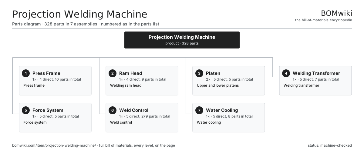
| # | Part | Qty | What it does |
|---|---|---|---|
| 1 | Press Frame 4 parts | 1× | Press frame |
| 2 | Ram Head 4 parts | 1× | Welding ram head |
| 3 | Platen 5 parts | 2× | Upper and lower platens |
| 4 | Welding Transformer 5 parts | 1× | Welding transformer |
| 5 | Force System 5 parts | 1× | Force system |
| 6 | Weld Control 5 parts | 1× | Weld control |
| 7 | Water Cooling 5 parts | 1× | Water cooling |
3D model
No 3D model yet. Have a CAD file of this? Add a 3D model — STL renders right on this page; STEP, FreeCAD, and OpenSCAD sources are welcome too (openly licensed, like all 3D models on BOMwiki).
Build & assembly graph
expand / collapse · shared sub-assemblies converge · links to related products · est. labourTap an assembly to expand/collapse · tap a part to open it · use “Open page” for any node · drag to pan, scroll to zoom.
Bill of materials for Projection Welding Machine
7 top-level lines · 51 rows shown · 328 parts total · indented to 3 levels| # | Item / sub-assembly | Part no. | Qty/assy | Ext. qty | Parts | Type |
|---|---|---|---|---|---|---|
| 1 | Press Frame 4 parts | projection-welding-machine-press-frame | 1× | 1 | 10 | assembly |
| 1.1 | Frame Weldment | projection-welding-machine-frame-weldment | 1× | 1 | · | part |
| 1.2 | Tie Bar | projection-welding-machine-tie-bar | 4× | 4 | · | part |
| 1.3 | Bolster Plate | projection-welding-machine-bolster | 1× | 1 | · | part |
| 1.4 | Levelling Foot | projection-welding-machine-foot | 4× | 4 | · | part |
| 2 | Ram Head 4 parts | projection-welding-machine-ram-head | 1× | 1 | 9 | assembly |
| 2.1 | Ram | projection-welding-machine-ram | 1× | 1 | · | part |
| 2.2 | Ram Guide | projection-welding-machine-ram-guide | 4× | 4 | · | part |
| 2.3 | Linear Guide Rail | linear-guide | 2× | 2 | · | part |
| 2.4 | Ram Bushing | projection-welding-machine-ram-bushing | 2× | 2 | · | part |
| 3 | Platen 5 parts | projection-welding-machine-platen | 2× | 2 | 5 | assembly |
| 3.1 | Platen Body | projection-welding-machine-platen-body | 1× | 2 | · | part |
| 3.2 | Electrode Insert | projection-welding-machine-electrode-insert | 1× | 2 | · | part |
| 3.3 | Tooling Plate | projection-welding-machine-tooling-plate | 1× | 2 | · | part |
| 3.4 | Cooling Passage | projection-welding-machine-water-passage | 1× | 2 | · | part |
| 3.5 | Current Shoe | projection-welding-machine-current-shoe | 1× | 2 | · | part |
| 4 | Welding Transformer 5 parts | projection-welding-machine-transformer | 1× | 1 | 7 | assembly |
| 4.1 | Transformer Core | projection-welding-machine-transformer-core | 1× | 1 | · | part |
| 4.2 | Primary Coil | projection-welding-machine-primary-coil | 1× | 1 | · | part |
| 4.3 | Secondary Loop | projection-welding-machine-secondary-loop | 1× | 1 | · | part |
| 4.4 | SCR Contactor 2 parts | projection-welding-machine-scr-contactor | 1× | 1 | 3 | assembly |
| 4.4.1 | Thyristor | projection-welding-machine-thyristor | 2× | 2 | · | part |
| 4.4.2 | Heat Sink | heat-sink | 1× | 1 | · | part |
| 4.5 | Tap Switch | projection-welding-machine-tap-switch | 1× | 1 | · | part |
| 5 | Force System 5 parts | projection-welding-machine-force-system | 1× | 1 | 5 | assembly |
| 5.1 | Force Cylinder | projection-welding-machine-force-cylinder | 1× | 1 | · | part |
| 5.2 | Proportional Valve | projection-welding-machine-proportional-valve | 1× | 1 | · | part |
| 5.3 | Air Reservoir | projection-welding-machine-air-tank | 1× | 1 | · | part |
| 5.4 | Force Sensor | projection-welding-machine-force-sensor | 1× | 1 | · | part |
| 5.5 | O-Ring Set | oring-set | 1× | 1 | · | part |
| 6 | Weld Control 5 parts | projection-welding-machine-control | 1× | 1 | 279 | assembly |
| 6.1 | Control Board 3 parts | projection-welding-machine-control-board | 1× | 1 | 142 | assembly |
| 6.1.1 | Bare PCB | pcb-bare | 1× | 1 | · | part |
| 6.1.2 | Microcontroller | mcu | 1× | 1 | · | part |
| 6.1.3 | SMD Passive (R/C/L) | smd-passives | 140× | 140 | · | part |
| 6.2 | Firing Board 3 parts | projection-welding-machine-firing-board | 1× | 1 | 53 | assembly |
| 6.2.1 | Bare PCB | pcb-bare | 1× | 1 | · | part |
| 6.2.2 | Gate Driver IC | gate-driver-ic | 2× | 2 | · | part |
| 6.2.3 | SMD Passive (R/C/L) | smd-passives | 50× | 50 | · | part |
| 6.3 | Weld Monitor Board 3 parts | projection-welding-machine-monitor-board | 1× | 1 | 82 | assembly |
| 6.3.1 | Bare PCB | pcb-bare | 1× | 1 | · | part |
| 6.3.2 | Current Sensor | current-sensor | 1× | 1 | · | part |
| 6.3.3 | SMD Passive (R/C/L) | smd-passives | 80× | 80 | · | part |
| 6.4 | LCD Panel | lcd-panel | 1× | 1 | · | part |
| 6.5 | Power Supply | power-supply | 1× | 1 | · | part |
| 7 | Water Cooling 5 parts | projection-welding-machine-cooling | 1× | 1 | 8 | assembly |
| 7.1 | Cooling Pump | projection-welding-machine-cooling-pump | 1× | 1 | · | part |
| 7.2 | Radiator | projection-welding-machine-radiator | 1× | 1 | · | part |
| 7.3 | Water Tank | projection-welding-machine-water-tank | 1× | 1 | · | part |
| 7.4 | Flow Switch | projection-welding-machine-flow-switch | 1× | 1 | · | part |
| 7.5 | Water Hose | projection-welding-machine-water-hose | 4× | 4 | · | part |
Related products
same domain, ranked by shared parts Industrial TIG Welder
492 parts · shares 5 with this page
Industrial TIG Welder
492 parts · shares 5 with this page
 Flash Butt Welding Machine
294 parts · shares 3 with this page
Electrochemical Grinder
425 parts · shares 3 with this page
Flash Butt Welding Machine
294 parts · shares 3 with this page
Electrochemical Grinder
425 parts · shares 3 with this page
 Wire Mesh Welding Machine
841 parts · shares 3 with this page
Chain Link Welding Machine
440 parts · shares 2 with this page
Bar Chamfering Machine
1,148 parts · shares 4 with this page
Wire Mesh Welding Machine
841 parts · shares 3 with this page
Chain Link Welding Machine
440 parts · shares 2 with this page
Bar Chamfering Machine
1,148 parts · shares 4 with this page
Sourcing: possible vendors
Prices, MOQ, and lead times are algorithmic estimates, not quotes, and not claims about these companies. Company mappings are curated by keyword; est. price band $10k–$1M. How estimates work| Vendor | HQ | Specialty | MOQ | Lead time |
|---|---|---|---|---|
|
🇩🇪DMG MORI
dmgmori.com ↗
|
Bielefeld, DE | Machine tools | 5 units | 12–20 wks |
|
🇯🇵Mazak
mazak.com ↗
|
Oguchi, JP | Machine tools | 5 units | 12–20 wks |
| haascnc.com ↗ | Oxnard, US | CNC machine tools | 5 units | 12–20 wks |
|
🇯🇵Okuma
okuma.com ↗
|
Niwa, JP | Machine tools | 5 units | 12–20 wks |
|
🇩🇪Trumpf
trumpf.com ↗
|
Ditzingen, DE | Laser & sheet-metal machines | 5 units | 12–20 wks |
879-word article