Multi-Spindle Automatic Lathe
ProductOverview
A multi-spindle automatic lathe is a high-production turning machine that works on several bars of stock at the same time. Where a single-spindle lathe holds one bar and performs each operation in sequence, a multi-spindle machine carries 4, 6, or 8 bars in a rotating Indexing Spindle Drum. Every station along the drum performs a different operation at the same moment: one station rough turns, the next forms a shoulder, another drills a hole, and the last parts off the finished piece. After each cycle the drum indexes one position so every bar advances to the next operation. The result is that one complete part falls off the machine on every cycle, even though each part takes several cycles of total cutting work.
This overlap of operations is the reason the machine exists. A part needing six operations on a single-spindle lathe is finished six times faster on a six-spindle machine, because all six operations run in parallel. Multi-spindle automatics dominate the production of high-volume turned parts such as fittings, bushings, fasteners, valve bodies, and electrical connector shells, where runs reach hundreds of thousands of identical pieces.
Spindle drum and work spindles
The heart of the machine is the Indexing Spindle Drum, a heavy Drum Body bored to carry the spindle bores on a pitch circle. Each Work Spindle holds a bar through a Spring Collet drawn tight by a Collet Draw Tube, and runs on a pair of angular-contact bearings using the shared Ball Bearing leaf. The spindles are driven together through the Spindle Drive Gear train so all bars rotate at cutting speed continuously.
Between cycles the drum must rotate exactly one station and stop with the spindle precisely aligned to the tools. The Drum Index Mechanism does this with a Geneva Index Cam that gives smooth intermittent motion, and a Index Locating Pin that seats into a tapered bore to lock the angular position to within a few microns. During cutting a Drum Clamp hydraulically locks the drum so cutting forces cannot shift it.
Tooling at each station
Each station is served by a Cross Slide that feeds a form or turning tool radially into the spinning bar, plus a shared End Tool Slide that carries axial tools such as drills and centering tools toward all spindles at once. Tools are mounted in Tool Holder blocks. Operations that need their own rotation, such as cross drilling or thread tapping, use a Cross-Drill Spindle attachment with its own Attachment Motor. The final station carries the Cutoff Blade that parts the finished piece from the bar.
Setting up a multi-spindle machine means distributing the part's operations across the stations so each takes roughly the same time, because the slowest station sets the cycle time. A well-balanced setup keeps every tool cutting and no station idle.
Bar feed and stock handling
Stock enters through the Bar Feed System system. Each spindle has a Bar Guide Tube guide tube that damps the whip of long bars spinning at high speed. After parting off, a Feed Finger advances the bar until it reaches the Bar Length Stop, which sets the length of the next part. A Bar Magazine holds spare bars and loads a fresh one automatically when the current bar runs out, allowing long unattended runs.
Bar diameter, hardness, and straightness all affect the achievable speed. Free-machining brass and leaded steels run fastest; stainless and titanium force lower speeds and heavier coolant.
Cam motion control
In the classic mechanical version every movement is timed by the Cam Motion Control. A single Camshaft carries a Cam Disc for each slide, and a Cam Follower roller converts the cam profile into slide motion, with a Coil Spring returning the follower. The cycle time is set by the Change Gear Set, which gear the camshaft to the main drive. Changing the part means grinding new cams or fitting a stored cam set, which is why mechanical multi-spindles suit very long production runs where setup cost is spread over many parts. CNC versions replace the cams with servo axes, trading some peak speed for fast changeover.
Main drive and power
The Main Drive Train uses a Main Drive Motor of 7.5-30 kW feeding a speed-range gearbox built around the shared Gearbox Housing and Helical Gear Pair leaves, with Drive Belt transmission to the spindle train. A Clutch & Brake Unit stops the cycle quickly at the end of a bar or on a fault. The whole machine sits on a heavy Machine Bed & Frame whose Bed Casting is stress-relieved grey iron, and runs on Hardened Slideways hardened to 55-60 HRC so the slides keep their accuracy over millions of cycles.
Coolant, chip handling, and guarding
Multi-spindle lathes generate chips faster than almost any other machine tool because many tools cut at once. The Coolant & Chip System system floods every cutting zone through a Coolant Nozzle fed by a high-flow Coolant Pump from a Coolant Tank, and a Chip Conveyor clears the chip pile continuously. The Enclosure & Guarding encloses the working area with Sheet Metal Panel panels, interlocked Access Door doors, and a Mist Extractor that captures coolant mist.
Control and use
The Electrical Control cabinet houses a PLC Module, a Spindle VFD for spindle speed, and a Operator Panel for setup and monitoring. In service the machine is set up once for a given part and then runs for hours or days producing identical pieces, monitored only for tool wear and bar replacement. Typical output ranges from 120 parts per hour for larger or harder work up to 1,200 parts per hour for small free-machining parts, with diameter tolerances held to 0.01-0.02 mm. The economics favour multi-spindle automatics whenever the production volume is high enough to absorb the long setup, which is why they remain standard equipment in fastener plants, plumbing-fitting works, and automotive component shops.
Multi-Spindle Automatic Lathe parts and their functions
9 top-level parts · 352 parts in total · full bill of materials below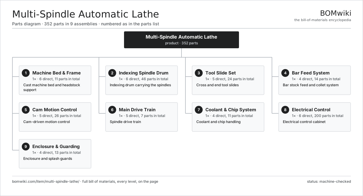
| # | Part | Qty | What it does |
|---|---|---|---|
| 1 | Machine Bed & Frame 6 parts | 1× | Cast machine bed and headstock support |
| 2 | Indexing Spindle Drum 6 parts | 1× | Indexing drum carrying the spindles |
| 3 | Tool Slide Set 5 parts | 1× | Cross and end tool slides |
| 4 | Bar Feed System 4 parts | 1× | Bar stock feed and collet system |
| 5 | Cam Motion Control 5 parts | 1× | Cam-driven motion control |
| 6 | Main Drive Train 5 parts | 1× | Spindle drive train |
| 7 | Coolant & Chip System 4 parts | 1× | Coolant and chip handling |
| 8 | Electrical Control 6 parts | 1× | Electrical control cabinet |
| 9 | Enclosure & Guarding 4 parts | 1× | Enclosure and splash guards |
3D model
No 3D model yet. Have a CAD file of this? Add a 3D model — STL renders right on this page; STEP, FreeCAD, and OpenSCAD sources are welcome too (openly licensed, like all 3D models on BOMwiki).
Build & assembly graph
expand / collapse · shared sub-assemblies converge · links to related products · est. labourTap an assembly to expand/collapse · tap a part to open it · use “Open page” for any node · drag to pan, scroll to zoom.
Bill of materials for Multi-Spindle Automatic Lathe
9 top-level lines · 71 rows shown · 352 parts total · indented to 3 levels| # | Item / sub-assembly | Part no. | Qty/assy | Ext. qty | Parts | Type |
|---|---|---|---|---|---|---|
| 1 | Machine Bed & Frame 6 parts | multi-spindle-lathe-bed | 1× | 1 | 11 | assembly |
| 1.1 | Bed Casting | multi-spindle-lathe-bed-casting | 1× | 1 | · | part |
| 1.2 | Headstock Housing | multi-spindle-lathe-headstock | 1× | 1 | · | part |
| 1.3 | End Housing | multi-spindle-lathe-end-housing | 1× | 1 | · | part |
| 1.4 | Hardened Slideways | multi-spindle-lathe-way-surfaces | 1× | 1 | · | part |
| 1.5 | Leveling Pad | multi-spindle-lathe-leveling-pads | 6× | 6 | · | part |
| 1.6 | Fastener Set | fastener-set | 1× | 1 | · | part |
| 2 | Indexing Spindle Drum 6 parts | multi-spindle-lathe-spindle-drum | 1× | 1 | 46 | assembly |
| 2.1 | Drum Body | multi-spindle-lathe-drum-body | 1× | 1 | · | part |
| 2.2 | Work Spindle 5 parts | multi-spindle-lathe-work-spindle | 6× | 6 | 6 | assembly |
| 2.2.1 | Spindle Shaft | multi-spindle-lathe-spindle-shaft | 1× | 6 | · | part |
| 2.2.2 | Spring Collet | multi-spindle-lathe-collet | 1× | 6 | · | part |
| 2.2.3 | Collet Draw Tube | multi-spindle-lathe-collet-tube | 1× | 6 | · | part |
| 2.2.4 | Ball Bearing | ball-bearing | 2× | 12 | · | part |
| 2.2.5 | Spindle Drive Gear | multi-spindle-lathe-spindle-gear | 1× | 6 | · | part |
| 2.3 | Drum Index Mechanism 3 parts | multi-spindle-lathe-index-mechanism | 1× | 1 | 3 | assembly |
| 2.3.1 | Geneva Index Cam | multi-spindle-lathe-geneva-cam | 1× | 1 | · | part |
| 2.3.2 | Index Locating Pin | multi-spindle-lathe-index-pin | 1× | 1 | · | part |
| 2.3.3 | Helical Gear Pair | gear-pair | 1× | 1 | · | part |
| 2.4 | Drum Clamp | multi-spindle-lathe-drum-clamp | 1× | 1 | · | part |
| 2.5 | Center Guide Tube | multi-spindle-lathe-center-tube | 1× | 1 | · | part |
| 2.6 | Ball Bearing | ball-bearing | 4× | 4 | · | part |
| 3 | Tool Slide Set 5 parts | multi-spindle-lathe-tool-slides | 1× | 1 | 24 | assembly |
| 3.1 | Cross Slide | multi-spindle-lathe-cross-slide | 6× | 6 | · | part |
| 3.2 | End Tool Slide | multi-spindle-lathe-end-slide | 1× | 1 | · | part |
| 3.3 | Tool Holder | multi-spindle-lathe-tool-holder | 8× | 8 | · | part |
| 3.4 | Cross-Drill Spindle 3 parts | multi-spindle-lathe-drill-spindle | 2× | 2 | 4 | assembly |
| 3.4.1 | Attachment Motor | multi-spindle-lathe-attach-motor | 1× | 2 | · | part |
| 3.4.2 | Ball Bearing | ball-bearing | 2× | 4 | · | part |
| 3.4.3 | Spring Collet | multi-spindle-lathe-collet | 1× | 2 | · | part |
| 3.5 | Cutoff Blade | multi-spindle-lathe-cutoff-blade | 1× | 1 | · | part |
| 4 | Bar Feed System 4 parts | multi-spindle-lathe-bar-feed | 1× | 1 | 14 | assembly |
| 4.1 | Bar Guide Tube | multi-spindle-lathe-feed-tubes | 6× | 6 | · | part |
| 4.2 | Feed Finger | multi-spindle-lathe-feed-finger | 6× | 6 | · | part |
| 4.3 | Bar Length Stop | multi-spindle-lathe-bar-stop | 1× | 1 | · | part |
| 4.4 | Bar Magazine | multi-spindle-lathe-magazine | 1× | 1 | · | part |
| 5 | Cam Motion Control 5 parts | multi-spindle-lathe-cam-drive | 1× | 1 | 26 | assembly |
| 5.1 | Camshaft | multi-spindle-lathe-camshaft | 1× | 1 | · | part |
| 5.2 | Cam Disc | multi-spindle-lathe-cam-disc | 8× | 8 | · | part |
| 5.3 | Cam Follower | multi-spindle-lathe-cam-follower | 8× | 8 | · | part |
| 5.4 | Change Gear Set | multi-spindle-lathe-change-gears | 1× | 1 | · | part |
| 5.5 | Coil Spring | coil-spring | 8× | 8 | · | part |
| 6 | Main Drive Train 5 parts | multi-spindle-lathe-main-drive | 1× | 1 | 7 | assembly |
| 6.1 | Main Drive Motor | multi-spindle-lathe-main-motor | 1× | 1 | · | part |
| 6.2 | Gearbox Housing | gearbox-housing | 1× | 1 | · | part |
| 6.3 | Helical Gear Pair | gear-pair | 2× | 2 | · | part |
| 6.4 | Drive Belt | drive-belt | 2× | 2 | · | part |
| 6.5 | Clutch & Brake Unit | multi-spindle-lathe-clutch-brake | 1× | 1 | · | part |
| 7 | Coolant & Chip System 4 parts | multi-spindle-lathe-coolant | 1× | 1 | 11 | assembly |
| 7.1 | Coolant Pump | multi-spindle-lathe-coolant-pump | 1× | 1 | · | part |
| 7.2 | Coolant Tank | multi-spindle-lathe-coolant-tank | 1× | 1 | · | part |
| 7.3 | Chip Conveyor | multi-spindle-lathe-chip-conveyor | 1× | 1 | · | part |
| 7.4 | Coolant Nozzle | multi-spindle-lathe-nozzle-set | 8× | 8 | · | part |
| 8 | Electrical Control 6 parts | multi-spindle-lathe-control | 1× | 1 | 200 | assembly |
| 8.1 | PLC Module 3 parts | multi-spindle-lathe-plc | 1× | 1 | 123 | assembly |
| 8.1.1 | Bare PCB | pcb-bare | 1× | 1 | · | part |
| 8.1.2 | Microcontroller | mcu | 2× | 2 | · | part |
| 8.1.3 | SMD Passive (R/C/L) | smd-passives | 120× | 120 | · | part |
| 8.2 | Power Supply | power-supply | 1× | 1 | · | part |
| 8.3 | Relay | relay | 12× | 12 | · | part |
| 8.4 | Operator Panel 3 parts | multi-spindle-lathe-operator-panel | 1× | 1 | 62 | assembly |
| 8.4.1 | LCD Panel | lcd-panel | 1× | 1 | · | part |
| 8.4.2 | Bare PCB | pcb-bare | 1× | 1 | · | part |
| 8.4.3 | SMD Passive (R/C/L) | smd-passives | 60× | 60 | · | part |
| 8.5 | Wire Bundle | wire-bundle | 1× | 1 | · | part |
| 8.6 | Spindle VFD | multi-spindle-lathe-vfd | 1× | 1 | · | part |
| 9 | Enclosure & Guarding 4 parts | multi-spindle-lathe-guard | 1× | 1 | 13 | assembly |
| 9.1 | Sheet Metal Panel | sheet-panel | 8× | 8 | · | part |
| 9.2 | Access Door | multi-spindle-lathe-door | 2× | 2 | · | part |
| 9.3 | Viewing Window | multi-spindle-lathe-window | 2× | 2 | · | part |
| 9.4 | Mist Extractor | multi-spindle-lathe-mist-extractor | 1× | 1 | · | part |
Related products
same domain, ranked by shared parts Creep-Feed Grinder
571 parts · shares 6 with this page
Creep-Feed Grinder
571 parts · shares 6 with this page
 Railway Wheel Lathe
1,201 parts · shares 6 with this page
Railway Wheel Lathe
1,201 parts · shares 6 with this page
 Rotary-Table Surface Grinder
172 parts · shares 6 with this page
Spline Rolling Machine
138 parts · shares 6 with this page
Upsetter Forging Machine
125 parts · shares 6 with this page
Blanking Press Line
350 parts · shares 5 with this page
Rotary-Table Surface Grinder
172 parts · shares 6 with this page
Spline Rolling Machine
138 parts · shares 6 with this page
Upsetter Forging Machine
125 parts · shares 6 with this page
Blanking Press Line
350 parts · shares 5 with this page
Sourcing: possible vendors
Prices, MOQ, and lead times are algorithmic estimates, not quotes, and not claims about these companies. Company mappings are curated by keyword; est. price band $10k–$1M. How estimates work| Vendor | HQ | Specialty | MOQ | Lead time |
|---|---|---|---|---|
|
🇩🇪DMG MORI
dmgmori.com ↗
|
Bielefeld, DE | Machine tools | 5 units | 12–20 wks |
|
🇯🇵Mazak
mazak.com ↗
|
Oguchi, JP | Machine tools | 5 units | 12–20 wks |
| haascnc.com ↗ | Oxnard, US | CNC machine tools | 5 units | 12–20 wks |
|
🇯🇵Okuma
okuma.com ↗
|
Niwa, JP | Machine tools | 5 units | 12–20 wks |
|
🇩🇪Trumpf
trumpf.com ↗
|
Ditzingen, DE | Laser & sheet-metal machines | 5 units | 12–20 wks |
1,105-word article