Press Brake
ProductAlso known as: Hydraulic Press Brake, CNC Press Brake
Overview
A Press Brake folds flat sheet metal along a straight line by pressing a top punch into a bottom V-die while the workpiece rests across the die opening. The machine in this entry is a 110 tonne, 3,100 mm CNC model: a size common in fabrication shops bending mild steel up to about 4 mm thick over the full length, or thicker material over a shorter span. Two hydraulic cylinders drive a moving upper beam called the ram, and a CNC control coordinates the ram, the back gauge that positions the sheet, and the crowning system that keeps the bend angle even.
The press brake earns its name from how it works. Air bending, the most common method, presses the punch only partway into the V opening so the sheet is bent across three lines of contact: the punch nose and the two die shoulders. Bend angle is set by how deep the ram descends, so one tool set produces a range of angles. The alternative, bottoming, drives the sheet fully into the die for a fixed angle and tighter tolerance at higher tonnage.
Frame and ram
The structural core is a Welded Steel C-Frame, a welded steel C-frame built from two Side Frame uprights tied together by the Lower Bed at the bottom and stiffening Cross Tie Plate members. The C shape leaves the front open so an operator can load sheet and let formed flanges swing up clear of the machine. Under load the open throat tends to spring apart, so the side plates are thick (typically 30 to 50 mm) and the whole weldment is stress-relieved after welding to remove residual stress that would otherwise distort it over time.
The Upper Beam (Ram) is the moving upper beam. It rides in four Ram Guide Way bronze gibs, two per side, that hold it square so it descends parallel to the bed within a few hundredths of a millimetre across the length. The bend quality depends directly on this parallelism, which is why the machine measures ram height on both ends.
Hydraulic drive
Force comes from a Hydraulic Drive of two Hydraulic Cylinder units, one near each upright. Each is a double-acting cylinder: a Piston Rod of hard-chromed steel runs through a Cylinder Head (Gland) that carries the rod seals, and oil on either side of the Piston either pushes the ram down or pulls it back up. Sealing is handled by an Oil Seal set and an O-Ring Set at each gland and piston.
The two cylinders do not share a mechanical link. Each follows its own command from the control, and each is measured by a Linear Encoder (Y Axis) linear scale. The control reads both encoders (the Y1 and Y2 axes) and trims oil flow to each cylinder independently, so the ram stays level even when the bend load sits off-centre. This electronic synchronisation replaced the older torsion-bar linkage and is what lets a hydraulic press brake hold angle on an asymmetric part.
Power unit
Oil is supplied by the Hydraulic Power Unit. A Pump Motor turns a Variable Piston Pump, a variable-displacement axial-piston pump whose Swash Plate tilts to change flow on demand, so the pump delivers high flow for the rapid approach and drops back during the slow working stroke. Oil leaves the pump through the Valve Block (Manifold), a machined manifold holding the Pressure Relief Valve that caps system pressure, the Directional Control Valve that selects advance, hold and return, and a Prefill (Fill) Valve on each cylinder that floods the large bore during fast approach so the pump does not have to fill it.
Closed-loop ram motion is metered by a Proportional Valve per cylinder, driven by the control to position the ram within 0.01 mm. A Accumulator stores oil for peak demand, a Oil Filter keeps contamination down to a 10-micron rating, and a Oil Cooler holds oil temperature in the working band. A Pressure Sensor on the system and pilot lines feeds pressure back to the control.
Tooling
The bend itself is formed by Bending Tooling. A segmented Top Punch mounts to the ram through a Punch Holder, and a Bottom V-Die sits in a Die Holder on the bed. Both tools are induction-hardened alloy steel. The V opening is chosen for the material: a common rule sizes the die at six to eight times the sheet thickness. Tools are split into segments and held by quick Tool Clamp units so an operator can build a tool length to match the box or channel being formed.
Positioning, crowning and control
A Back Gauge sets where the sheet sits front-to-back. Its X Axis sets flange depth and its R Axis sets finger height, each a Servo Motor turning a Ball Screw on a Linear Guide Rail. The operator slides the sheet in until it touches the Gauge Finger stops, then the bend begins.
Because the loaded frame deflects, the bend would otherwise come out tighter at the ends than the middle. The Crowning System system cancels this by lifting the bed centre with a bar of Crowning Wedge pairs driven by the Crowning Motor. All of it is run by the CNC Control: the CNC Control Board computes the bend sequence, the Touchscreen HMI programs it, and the Safety System light curtain stops the ram if a hand crosses the tool line.
Press Brake parts and their functions
11 top-level parts · 968 parts in total · full bill of materials below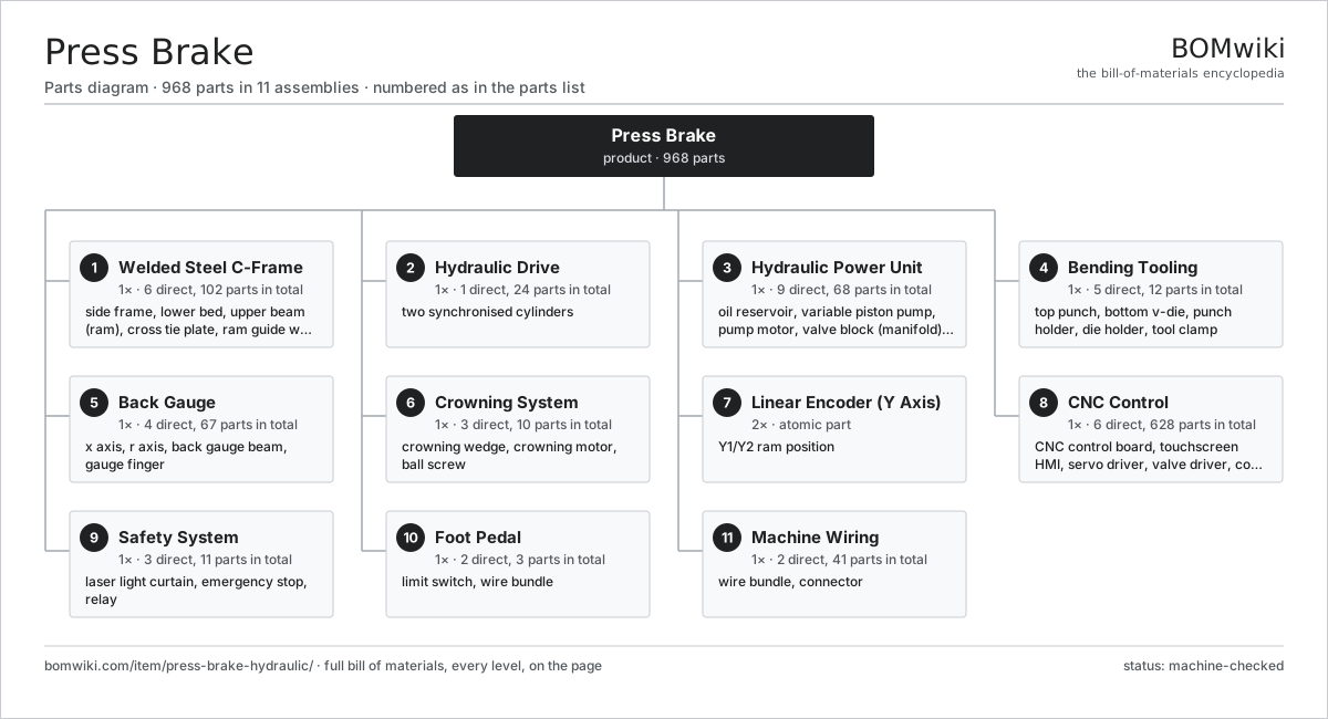
| # | Part | Qty | What it does |
|---|---|---|---|
| 1 | Welded Steel C-Frame 6 parts | 1× | Stress-relieved steel weldment reacting the bending load between bed and ram. |
| 2 | Hydraulic Drive 1 parts | 1× | two synchronised cylinders |
| 3 | Hydraulic Power Unit 9 parts | 1× | Tank, pump, motor and valves supplying metered oil to the cylinders. |
| 4 | Bending Tooling 5 parts | 1× | Punch and die set that forms the bend, held by clamps along the beam. |
| 5 | Back Gauge 4 parts | 1× | Motorised X/R positioning stop locating the sheet behind the dies. |
| 6 | Crowning System 3 parts | 1× | Bed-deflection compensator keeping the bend angle uniform along the length. |
| 7 | Linear Encoder (Y Axis) | 2× | Y1/Y2 ram position |
| 8 | CNC Control 6 parts | 1× | Compute, drives and operator interface running the bending program. |
| 9 | Safety System 3 parts | 1× | Laser guard and e-stops that halt the ram on intrusion. |
| 10 | Foot Pedal 2 parts | 1× | Guarded foot switch initiating and holding the bending stroke. |
| 11 | Machine Wiring 2 parts | 1× | Harnesses and connectors tying the drives, sensors and control together. |
3D model
No 3D model yet. Have a CAD file of this? Add a 3D model — STL renders right on this page; STEP, FreeCAD, and OpenSCAD sources are welcome too (openly licensed, like all 3D models on BOMwiki).
Build & assembly graph
expand / collapse · shared sub-assemblies converge · links to related products · est. labourTap an assembly to expand/collapse · tap a part to open it · use “Open page” for any node · drag to pan, scroll to zoom.
Bill of materials for Press Brake
11 top-level lines · 104 rows shown · 968 parts total · indented to 3 levels| # | Item / sub-assembly | Part no. | Qty/assy | Ext. qty | Parts | Type |
|---|---|---|---|---|---|---|
| 1 | Welded Steel C-Frame 6 parts | press-brake-hydraulic-frame | 1× | 1 | 102 | assembly |
| 1.1 | Side Frame | press-brake-hydraulic-side-frame | 2× | 2 | · | part |
| 1.2 | Lower Bed | press-brake-hydraulic-bed | 1× | 1 | · | part |
| 1.3 | Upper Beam (Ram) | press-brake-hydraulic-ram | 1× | 1 | · | part |
| 1.4 | Cross Tie Plate | press-brake-hydraulic-tie-plate | 4× | 4 | · | part |
| 1.5 | Ram Guide Way | press-brake-hydraulic-ram-guide | 4× | 4 | · | part |
| 1.6 | Fastener Set | fastener-set | 90× | 90 | · | part |
| 2 | Hydraulic Drive 1 parts | press-brake-hydraulic-drive | 1× | 1 | 24 | assembly |
| 2.1 | Hydraulic Cylinder 6 parts | press-brake-hydraulic-cylinder | 2× | 2 | 12 | assembly |
| 2.1.1 | Cylinder Body | press-brake-hydraulic-cylinder-body | 1× | 2 | · | part |
| 2.1.2 | Piston | press-brake-hydraulic-piston | 1× | 2 | · | part |
| 2.1.3 | Piston Rod | press-brake-hydraulic-piston-rod | 1× | 2 | · | part |
| 2.1.4 | Cylinder Head (Gland) | press-brake-hydraulic-cylinder-head | 1× | 2 | · | part |
| 2.1.5 | Oil Seal | oil-seal | 3× | 6 | · | part |
| 2.1.6 | O-Ring Set | oring-set | 5× | 10 | · | part |
| 3 | Hydraulic Power Unit 9 parts | press-brake-hydraulic-power-unit | 1× | 1 | 68 | assembly |
| 3.1 | Oil Reservoir | press-brake-hydraulic-tank | 1× | 1 | · | part |
| 3.2 | Variable Piston Pump 6 parts | press-brake-hydraulic-pump | 1× | 1 | 19 | assembly |
| 3.2.1 | Cylinder Barrel | press-brake-hydraulic-pump-barrel | 1× | 1 | · | part |
| 3.2.2 | Swash Plate | press-brake-hydraulic-swash-plate | 1× | 1 | · | part |
| 3.2.3 | Pump Piston & Shoe | press-brake-hydraulic-pump-piston | 9× | 9 | · | part |
| 3.2.4 | Ball Bearing | ball-bearing | 2× | 2 | · | part |
| 3.2.5 | Oil Seal | oil-seal | 2× | 2 | · | part |
| 3.2.6 | O-Ring Set | oring-set | 4× | 4 | · | part |
| 3.3 | Pump Motor 5 parts | press-brake-hydraulic-motor | 1× | 1 | 26 | assembly |
| 3.3.1 | Stator Assembly 3 parts + deeper › | stator-assembly | 1× | 1 | 3 | assembly |
| 3.3.2 | Rotor Assembly 4 parts + deeper › | rotor-assembly | 1× | 1 | 19 | assembly |
| 3.3.3 | Motor Housing | press-brake-hydraulic-motor-housing | 1× | 1 | · | part |
| 3.3.4 | Ball Bearing | ball-bearing | 2× | 2 | · | part |
| 3.3.5 | Oil Seal | oil-seal | 1× | 1 | · | part |
| 3.4 | Valve Block (Manifold) 5 parts | press-brake-hydraulic-valve-block | 1× | 1 | 14 | assembly |
| 3.4.1 | Pressure Relief Valve | press-brake-hydraulic-relief-valve | 1× | 1 | · | part |
| 3.4.2 | Directional Control Valve | press-brake-hydraulic-directional-valve | 1× | 1 | · | part |
| 3.4.3 | Prefill (Fill) Valve | press-brake-hydraulic-fill-valve | 2× | 2 | · | part |
| 3.4.4 | Check Valve | press-brake-hydraulic-check-valve | 2× | 2 | · | part |
| 3.4.5 | O-Ring Set | oring-set | 8× | 8 | · | part |
| 3.5 | Proportional Valve | press-brake-hydraulic-prop-valve | 2× | 2 | · | part |
| 3.6 | Accumulator | press-brake-hydraulic-accumulator | 1× | 1 | · | part |
| 3.7 | Oil Filter | press-brake-hydraulic-filter | 2× | 2 | · | part |
| 3.8 | Oil Cooler | press-brake-hydraulic-cooler | 1× | 1 | · | part |
| 3.9 | Pressure Sensor | pressure-sensor | 2× | 2 | · | part |
| 4 | Bending Tooling 5 parts | press-brake-hydraulic-tooling | 1× | 1 | 12 | assembly |
| 4.1 | Top Punch | press-brake-hydraulic-punch | 1× | 1 | · | part |
| 4.2 | Bottom V-Die | press-brake-hydraulic-vdie | 1× | 1 | · | part |
| 4.3 | Punch Holder | press-brake-hydraulic-punch-holder | 1× | 1 | · | part |
| 4.4 | Die Holder | press-brake-hydraulic-die-holder | 1× | 1 | · | part |
| 4.5 | Tool Clamp | press-brake-hydraulic-clamp | 8× | 8 | · | part |
| 5 | Back Gauge 4 parts | press-brake-hydraulic-back-gauge | 1× | 1 | 67 | assembly |
| 5.1 | X Axis 5 parts | press-brake-hydraulic-bg-x-axis | 1× | 1 | 31 | assembly |
| 5.1.1 | Servo Motor 4 parts + deeper › | servo-motor | 1× | 1 | 24 | assembly |
| 5.1.2 | Ball Screw | ball-screw | 1× | 1 | · | part |
| 5.1.3 | Linear Guide Rail | linear-guide | 2× | 2 | · | part |
| 5.1.4 | Ball Bearing | ball-bearing | 2× | 2 | · | part |
| 5.1.5 | Limit Switch | press-brake-hydraulic-limit-switch | 2× | 2 | · | part |
| 5.2 | R Axis 5 parts | press-brake-hydraulic-bg-r-axis | 1× | 1 | 31 | assembly |
| 5.2.1 | Servo Motor 4 parts + deeper › | servo-motor | 1× | 1 | 24 | assembly |
| 5.2.2 | Ball Screw | ball-screw | 1× | 1 | · | part |
| 5.2.3 | Linear Guide Rail | linear-guide | 2× | 2 | · | part |
| 5.2.4 | Ball Bearing | ball-bearing | 2× | 2 | · | part |
| 5.2.5 | Limit Switch | press-brake-hydraulic-limit-switch | 2× | 2 | · | part |
| 5.3 | Back Gauge Beam | press-brake-hydraulic-bg-beam | 1× | 1 | · | part |
| 5.4 | Gauge Finger | press-brake-hydraulic-finger | 4× | 4 | · | part |
| 6 | Crowning System 3 parts | press-brake-hydraulic-crowning | 1× | 1 | 10 | assembly |
| 6.1 | Crowning Wedge | press-brake-hydraulic-crown-wedge | 8× | 8 | · | part |
| 6.2 | Crowning Motor | press-brake-hydraulic-crown-motor | 1× | 1 | · | part |
| 6.3 | Ball Screw | ball-screw | 1× | 1 | · | part |
| 7 | Linear Encoder (Y Axis) | press-brake-hydraulic-y-encoder | 2× | 2 | · | part |
| 8 | CNC Control 6 parts | press-brake-hydraulic-cnc | 1× | 1 | 628 | assembly |
| 8.1 | CNC Control Board 5 parts | press-brake-hydraulic-control-board | 1× | 1 | 296 | assembly |
| 8.1.1 | Bare PCB | pcb-bare | 1× | 1 | · | part |
| 8.1.2 | Compute SoC Module | press-brake-hydraulic-soc | 1× | 1 | · | part |
| 8.1.3 | Microcontroller | mcu | 2× | 2 | · | part |
| 8.1.4 | SMD Passive (R/C/L) | smd-passives | 280× | 280 | · | part |
| 8.1.5 | Connector | connector | 12× | 12 | · | part |
| 8.2 | Touchscreen HMI 4 parts | press-brake-hydraulic-touchscreen | 1× | 1 | 63 | assembly |
| 8.2.1 | LCD Panel | lcd-panel | 1× | 1 | · | part |
| 8.2.2 | Touch Digitizer | press-brake-hydraulic-touch-digitizer | 1× | 1 | · | part |
| 8.2.3 | Bare PCB | pcb-bare | 1× | 1 | · | part |
| 8.2.4 | SMD Passive (R/C/L) | smd-passives | 60× | 60 | · | part |
| 8.3 | Servo Driver 4 parts | press-brake-hydraulic-servo-driver | 2× | 2 | 93 | assembly |
| 8.3.1 | Bare PCB | pcb-bare | 1× | 2 | · | part |
| 8.3.2 | IGBT Power Module | press-brake-hydraulic-igbt | 1× | 2 | · | part |
| 8.3.3 | Microcontroller | mcu | 1× | 2 | · | part |
| 8.3.4 | SMD Passive (R/C/L) | smd-passives | 90× | 180 | · | part |
| 8.4 | Valve Driver 3 parts | press-brake-hydraulic-valve-driver | 1× | 1 | 72 | assembly |
| 8.4.1 | Bare PCB | pcb-bare | 1× | 1 | · | part |
| 8.4.2 | IGBT Power Module | press-brake-hydraulic-igbt | 1× | 1 | · | part |
| 8.4.3 | SMD Passive (R/C/L) | smd-passives | 70× | 70 | · | part |
| 8.5 | Control Power Supply | press-brake-hydraulic-psu | 1× | 1 | · | part |
| 8.6 | Relay | relay | 10× | 10 | · | part |
| 9 | Safety System 3 parts | press-brake-hydraulic-safety | 1× | 1 | 11 | assembly |
| 9.1 | Laser Light Curtain 4 parts | press-brake-hydraulic-light-curtain | 1× | 1 | 6 | assembly |
| 9.1.1 | Bare PCB | pcb-bare | 2× | 2 | · | part |
| 9.1.2 | Connector | connector | 2× | 2 | · | part |
| 9.1.3 | Laser Emitter | press-brake-hydraulic-laser-diode | 1× | 1 | · | part |
| 9.1.4 | Receiver Array | press-brake-hydraulic-photodetector | 1× | 1 | · | part |
| 9.2 | Emergency Stop | press-brake-hydraulic-estop | 2× | 2 | · | part |
| 9.3 | Relay | relay | 3× | 3 | · | part |
| 10 | Foot Pedal 2 parts | press-brake-hydraulic-foot-pedal | 1× | 1 | 3 | assembly |
| 10.1 | Limit Switch | press-brake-hydraulic-limit-switch | 2× | 2 | · | part |
| 10.2 | Wire Bundle | wire-bundle | 1× | 1 | · | part |
| 11 | Machine Wiring 2 parts | press-brake-hydraulic-wiring | 1× | 1 | 41 | assembly |
| 11.1 | Wire Bundle | wire-bundle | 5× | 5 | · | part |
| 11.2 | Connector | connector | 36× | 36 | · | part |
Related products
same domain, ranked by shared parts Bevel Gear Generator
201 parts · shares 5 with this page
Camshaft Grinder
489 parts · shares 5 with this page
Centering and Facing Machine
1,419 parts · shares 5 with this page
Bevel Gear Generator
201 parts · shares 5 with this page
Camshaft Grinder
489 parts · shares 5 with this page
Centering and Facing Machine
1,419 parts · shares 5 with this page
 CO2 Laser Cutting Machine
227 parts · shares 5 with this page
CO2 Laser Cutting Machine
227 parts · shares 5 with this page
 Crankshaft Grinder
511 parts · shares 5 with this page
Crankshaft Grinder
511 parts · shares 5 with this page
Sourcing: possible vendors
Prices, MOQ, and lead times are algorithmic estimates, not quotes, and not claims about these companies. Company mappings are curated by keyword; est. price band $10k–$1M. How estimates work| Vendor | HQ | Specialty | MOQ | Lead time |
|---|---|---|---|---|
|
🇩🇪DMG MORI
dmgmori.com ↗
|
Bielefeld, DE | Machine tools | 5 units | 12–20 wks |
|
🇯🇵Mazak
mazak.com ↗
|
Oguchi, JP | Machine tools | 5 units | 12–20 wks |
| haascnc.com ↗ | Oxnard, US | CNC machine tools | 5 units | 12–20 wks |
|
🇯🇵Okuma
okuma.com ↗
|
Niwa, JP | Machine tools | 5 units | 12–20 wks |
|
🇩🇪Trumpf
trumpf.com ↗
|
Ditzingen, DE | Laser & sheet-metal machines | 5 units | 12–20 wks |
1,002-word article