Centering and Facing Machine
ProductOverview
A centering and facing machine prepares the ends of a shaft so it can be held between centres on a lathe, grinder or measuring rig later. It does two jobs at each end: it faces the end flat and square to the axis, then it drills a 60-degree centre hole into that faced surface. The centre holes are the seats that lathe and grinder centres sit in, so their position and angle set how true the shaft will run on every later operation. This machine works on both ends at once. The shaft is clamped horizontally in the Workpiece Vise between two opposed Left Spindle Head and Right Spindle Head spindle heads, and a single cycle faces and centre-drills both ends together.
The whole machine sits on the Machine Bed, a heavy cast or welded base that holds both heads on one common axis. Each head rides a Head Feed Slide along the Slideway so it can advance into the shaft end and retract. Long shafts are backed up in the middle by the Steady Rest so they do not sag. The Coolant System floods the cutters, and the Control Cabinet sequences both heads. This unit handles shafts roughly 10 to 120 mm in diameter and 100 to 1,500 mm long, and cuts centre holes from B1.6 up to B10 in the DIN 332 series.
How it works
A cycle runs in two stages at each end: face first, then centre-drill. The operator or a loader sets the shaft into the Prism Clamp Jaw prisms, the Centring Screw draws both jaws in together so the shaft is held on its centreline, and a Pneumatic Cylinder applies the final clamp force. A Pressure Sensor confirms the grip before the heads are allowed to feed.
With the shaft clamped, the Facing Cutter Spindle at each head spins up and the feed slide drives the Facing Cutter Head across the end of the shaft. This removes the saw-cut or forged end and leaves a face that is flat and square to the axis, which matters because the centre hole has to be drilled into a true surface or it will run out. The facing spindle then retracts and the Center Drill Spindle feeds the Center Drill into the faced end. A centre drill is a combined drill point and 60-degree countersink, so in one plunge it makes the pilot bore and the cone the live or dead centre will seat against. Both heads run the same sequence at the same time, so a shaft leaves the machine with matched centres at both ends in one handling.
Spindle heads and tooling
Each Spindle Head Body carries two spindles, one for facing and one for drilling, so the head does not have to swap tools mid-cycle. The Facing Cutter Spindle runs on angular-contact Ball Bearing sets and is sealed with Oil Seal front and rear; it turns the cutter at 300-3,000 rpm depending on shaft diameter. The Center Drill runs faster, 500-4,000 rpm, because it cuts on a small diameter. Each spindle is driven through a Helical Gear Pair in the Gearbox Housing from a Servo Motor, so speed can be set per job from the controller.
Tools mount in a Tool Collet at each spindle nose. The facing cutter is normally an indexable-insert head so worn edges are indexed or replaced without regrinding. The centre drill follows the DIN 332 form, which fixes the 60-degree cone angle and the small pilot diameter for each size code, so a B-form drill leaves a protected centre with a clearance counterbore that keeps the cone from being damaged in handling. Both tools take the full cut on every shaft, so the cutter inserts and the centre drill are the wear items the operator checks most often.
Clamping and feed
Holding the shaft true is half the job. The Workpiece Vise uses V-prism jaws that locate any round shaft on its centreline regardless of diameter, so the two centre holes end up on the same axis even when the bar stock is not perfectly round. For long or slender shafts the Steady Rest adds a mid-span support: three Support Roller bear on the shaft and stop it bowing or whipping while the ends are cut.
Each head feeds on a Head Feed Slide built from a Ball Screw and Linear Guide Rail driven by a Servo Motor with an Encoder for position. The servo feed sets facing depth and centre-hole depth to a programmed value, and because the depth is controlled rather than fixed by a stop, the same machine runs different shaft lengths and centre sizes by loading a new recipe at the Touchscreen HMI. The Motion Controller coordinates the two heads so they reach the work together and the cycle stays balanced.
Materials, variants and use
Cutter inserts and centre drills are carbide or hardened high-speed steel because they take the cutting load on every part. The spindles, slideways and vise jaws are hardened and ground steel so the machine holds its accuracy under repeated clamping. Coolant from the Coolant Pump flushes chips out of the deepening centre hole through the Coolant Nozzle, which matters because a packed hole will break a small centre drill.
Simpler versions of the machine work one end at a time or use a manual lever feed, while production versions like this one face and centre-drill both ends under CNC with automatic clamping. Centering and facing machines are used wherever shafts are made in volume and have to run true later: motor and gearbox shafts, axles, spindles, rolls and long turned parts that move on to a lathe or cylindrical grinder. The work zone runs behind Guarding & Interlocks with interlocked doors so the heads stop if a door is opened while the spindles are turning.
Centering and Facing Machine parts and their functions
9 top-level parts · 1,419 parts in total · full bill of materials below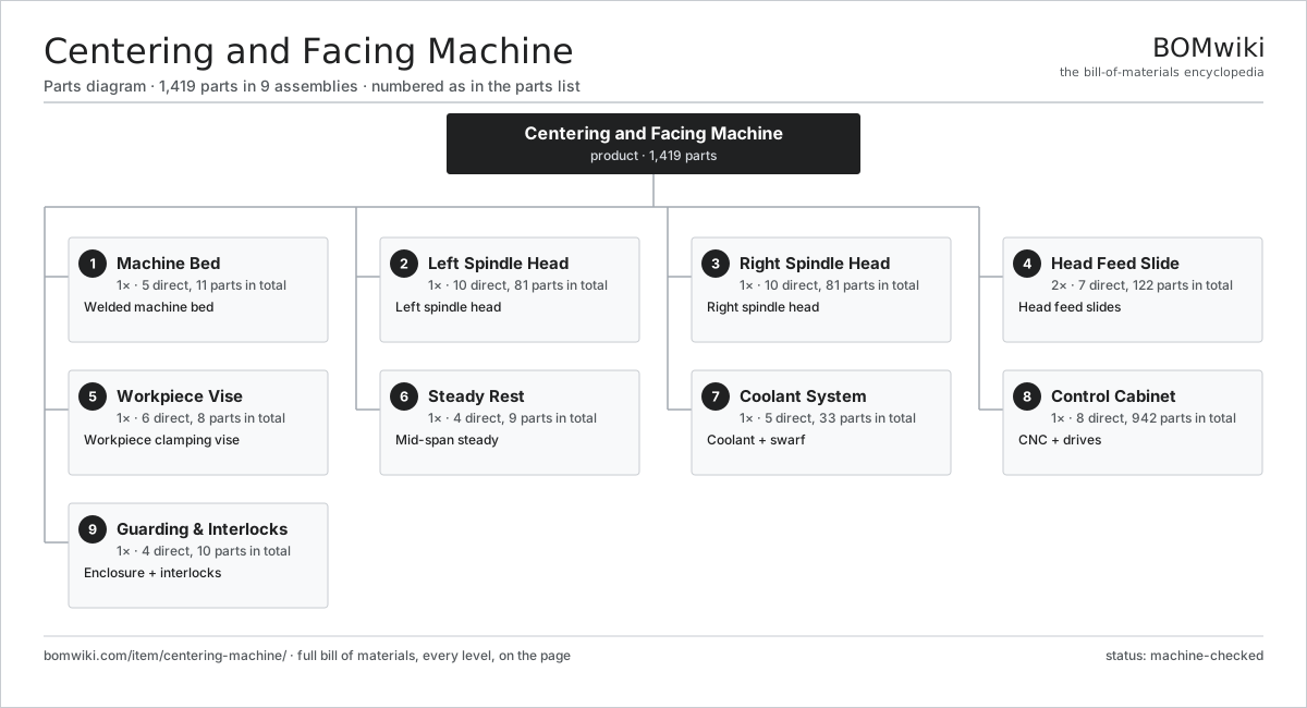
| # | Part | Qty | What it does |
|---|---|---|---|
| 1 | Machine Bed 5 parts | 1× | Welded machine bed |
| 2 | Left Spindle Head 10 parts | 1× | Left spindle head |
| 3 | Right Spindle Head 10 parts | 1× | Right spindle head |
| 4 | Head Feed Slide 7 parts | 2× | Head feed slides |
| 5 | Workpiece Vise 6 parts | 1× | Workpiece clamping vise |
| 6 | Steady Rest 4 parts | 1× | Mid-span steady |
| 7 | Coolant System 5 parts | 1× | Coolant + swarf |
| 8 | Control Cabinet 8 parts | 1× | CNC + drives |
| 9 | Guarding & Interlocks 4 parts | 1× | Enclosure + interlocks |
3D model
No 3D model yet. Have a CAD file of this? Add a 3D model — STL renders right on this page; STEP, FreeCAD, and OpenSCAD sources are welcome too (openly licensed, like all 3D models on BOMwiki).
Build & assembly graph
expand / collapse · shared sub-assemblies converge · links to related products · est. labourTap an assembly to expand/collapse · tap a part to open it · use “Open page” for any node · drag to pan, scroll to zoom.
Bill of materials for Centering and Facing Machine
9 top-level lines · 124 rows shown · 1,419 parts total · indented to 3 levels| # | Item / sub-assembly | Part no. | Qty/assy | Ext. qty | Parts | Type |
|---|---|---|---|---|---|---|
| 1 | Machine Bed 5 parts | centering-machine-bed | 1× | 1 | 11 | assembly |
| 1.1 | Bed Casting | centering-machine-bed-casting | 1× | 1 | · | part |
| 1.2 | Slideway | centering-machine-bed-ways | 2× | 2 | · | part |
| 1.3 | Leveling Foot | centering-machine-leveling-foot | 6× | 6 | · | part |
| 1.4 | Chip Tray | centering-machine-chip-tray | 1× | 1 | · | part |
| 1.5 | Fastener Set | fastener-set | 1× | 1 | · | part |
| 2 | Left Spindle Head 10 parts | centering-machine-left-head | 1× | 1 | 81 | assembly |
| 2.1 | Spindle Head Body | centering-machine-head-body | 1× | 1 | · | part |
| 2.2 | Facing Cutter Spindle 5 parts | centering-machine-facing-spindle | 1× | 1 | 9 | assembly |
| 2.2.1 | Spindle Shaft | centering-machine-spindle-shaft | 1× | 1 | · | part |
| 2.2.2 | Quill Sleeve | centering-machine-spindle-quill | 1× | 1 | · | part |
| 2.2.3 | Ball Bearing | ball-bearing | 4× | 4 | · | part |
| 2.2.4 | Oil Seal | oil-seal | 2× | 2 | · | part |
| 2.2.5 | Tool Collet | centering-machine-tool-collet | 1× | 1 | · | part |
| 2.3 | Center Drill Spindle 5 parts | centering-machine-drill-spindle | 1× | 1 | 8 | assembly |
| 2.3.1 | Spindle Shaft | centering-machine-spindle-shaft | 1× | 1 | · | part |
| 2.3.2 | Quill Sleeve | centering-machine-spindle-quill | 1× | 1 | · | part |
| 2.3.3 | Ball Bearing | ball-bearing | 3× | 3 | · | part |
| 2.3.4 | Oil Seal | oil-seal | 2× | 2 | · | part |
| 2.3.5 | Tool Collet | centering-machine-tool-collet | 1× | 1 | · | part |
| 2.4 | Facing Cutter Head | centering-machine-facing-cutter | 1× | 1 | · | part |
| 2.5 | Center Drill | centering-machine-center-drill | 1× | 1 | · | part |
| 2.6 | Servo Motor 4 parts | servo-motor | 2× | 2 | 24 | assembly |
| 2.6.1 | Stator Assembly 3 parts + deeper › | stator-assembly | 1× | 2 | 3 | assembly |
| 2.6.2 | Rotor Assembly 4 parts + deeper › | rotor-assembly | 1× | 2 | 19 | assembly |
| 2.6.3 | Encoder | encoder | 1× | 2 | · | part |
| 2.6.4 | Motor Housing | motor-housing | 1× | 2 | · | part |
| 2.7 | Gearbox Housing | gearbox-housing | 1× | 1 | · | part |
| 2.8 | Helical Gear Pair | gear-pair | 2× | 2 | · | part |
| 2.9 | Ball Bearing | ball-bearing | 6× | 6 | · | part |
| 2.10 | Oil Seal | oil-seal | 4× | 4 | · | part |
| 3 | Right Spindle Head 10 parts | centering-machine-right-head | 1× | 1 | 81 | assembly |
| 3.1 | Spindle Head Body | centering-machine-head-body | 1× | 1 | · | part |
| 3.2 | Facing Cutter Spindle 5 parts | centering-machine-facing-spindle | 1× | 1 | 9 | assembly |
| 3.2.1 | Spindle Shaft | centering-machine-spindle-shaft | 1× | 1 | · | part |
| 3.2.2 | Quill Sleeve | centering-machine-spindle-quill | 1× | 1 | · | part |
| 3.2.3 | Ball Bearing | ball-bearing | 4× | 4 | · | part |
| 3.2.4 | Oil Seal | oil-seal | 2× | 2 | · | part |
| 3.2.5 | Tool Collet | centering-machine-tool-collet | 1× | 1 | · | part |
| 3.3 | Center Drill Spindle 5 parts | centering-machine-drill-spindle | 1× | 1 | 8 | assembly |
| 3.3.1 | Spindle Shaft | centering-machine-spindle-shaft | 1× | 1 | · | part |
| 3.3.2 | Quill Sleeve | centering-machine-spindle-quill | 1× | 1 | · | part |
| 3.3.3 | Ball Bearing | ball-bearing | 3× | 3 | · | part |
| 3.3.4 | Oil Seal | oil-seal | 2× | 2 | · | part |
| 3.3.5 | Tool Collet | centering-machine-tool-collet | 1× | 1 | · | part |
| 3.4 | Facing Cutter Head | centering-machine-facing-cutter | 1× | 1 | · | part |
| 3.5 | Center Drill | centering-machine-center-drill | 1× | 1 | · | part |
| 3.6 | Servo Motor 4 parts | servo-motor | 2× | 2 | 24 | assembly |
| 3.6.1 | Stator Assembly 3 parts + deeper › | stator-assembly | 1× | 2 | 3 | assembly |
| 3.6.2 | Rotor Assembly 4 parts + deeper › | rotor-assembly | 1× | 2 | 19 | assembly |
| 3.6.3 | Encoder | encoder | 1× | 2 | · | part |
| 3.6.4 | Motor Housing | motor-housing | 1× | 2 | · | part |
| 3.7 | Gearbox Housing | gearbox-housing | 1× | 1 | · | part |
| 3.8 | Helical Gear Pair | gear-pair | 2× | 2 | · | part |
| 3.9 | Ball Bearing | ball-bearing | 6× | 6 | · | part |
| 3.10 | Oil Seal | oil-seal | 4× | 4 | · | part |
| 4 | Head Feed Slide 7 parts | centering-machine-feed-slide | 2× | 2 | 122 | assembly |
| 4.1 | Linear Guide Rail | linear-guide | 2× | 4 | · | part |
| 4.2 | Ball Screw | ball-screw | 1× | 2 | · | part |
| 4.3 | Servo Motor 4 parts | servo-motor | 1× | 2 | 24 | assembly |
| 4.3.1 | Stator Assembly 3 parts + deeper › | stator-assembly | 1× | 2 | 3 | assembly |
| 4.3.2 | Rotor Assembly 4 parts + deeper › | rotor-assembly | 1× | 2 | 19 | assembly |
| 4.3.3 | Encoder | encoder | 1× | 2 | · | part |
| 4.3.4 | Motor Housing | motor-housing | 1× | 2 | · | part |
| 4.4 | Servo Drive 4 parts | servo-drive | 1× | 2 | 91 | assembly |
| 4.4.1 | Bare PCB | pcb-bare | 1× | 2 | · | part |
| 4.4.2 | IGBT Power Module | igbt-module | 1× | 2 | · | part |
| 4.4.3 | Gate Driver Board 3 parts + deeper › | gate-driver-board | 1× | 2 | 87 | assembly |
| 4.4.4 | DC-Link Capacitor | dc-link-cap | 2× | 4 | · | part |
| 4.5 | Encoder | encoder | 1× | 2 | · | part |
| 4.6 | Slide Carriage | centering-machine-slide-plate | 1× | 2 | · | part |
| 4.7 | Ball Bearing | ball-bearing | 2× | 4 | · | part |
| 5 | Workpiece Vise 6 parts | centering-machine-clamp-vise | 1× | 1 | 8 | assembly |
| 5.1 | Vise Body | centering-machine-vise-body | 1× | 1 | · | part |
| 5.2 | Prism Clamp Jaw | centering-machine-vise-jaw | 2× | 2 | · | part |
| 5.3 | Centring Screw | centering-machine-vise-screw | 1× | 1 | · | part |
| 5.4 | Pneumatic Cylinder | pneumatic-cylinder | 1× | 1 | · | part |
| 5.5 | Pressure Sensor | pressure-sensor | 1× | 1 | · | part |
| 5.6 | Coil Spring | coil-spring | 2× | 2 | · | part |
| 6 | Steady Rest 4 parts | centering-machine-steady-rest | 1× | 1 | 9 | assembly |
| 6.1 | Steady Frame | centering-machine-steady-body | 1× | 1 | · | part |
| 6.2 | Support Roller | centering-machine-steady-roller | 3× | 3 | · | part |
| 6.3 | Ball Bearing | ball-bearing | 3× | 3 | · | part |
| 6.4 | Roller Adjust Screw | centering-machine-steady-screw | 2× | 2 | · | part |
| 7 | Coolant System 5 parts | centering-machine-coolant-system | 1× | 1 | 33 | assembly |
| 7.1 | Coolant Tank | centering-machine-coolant-tank | 1× | 1 | · | part |
| 7.2 | Coolant Pump 5 parts | centering-machine-coolant-pump | 1× | 1 | 26 | assembly |
| 7.2.1 | Stator Assembly 3 parts + deeper › | stator-assembly | 1× | 1 | 3 | assembly |
| 7.2.2 | Rotor Assembly 4 parts + deeper › | rotor-assembly | 1× | 1 | 19 | assembly |
| 7.2.3 | Pump Impeller | centering-machine-pump-impeller | 1× | 1 | · | part |
| 7.2.4 | Ball Bearing | ball-bearing | 2× | 2 | · | part |
| 7.2.5 | Oil Seal | oil-seal | 1× | 1 | · | part |
| 7.3 | Coolant Nozzle | centering-machine-coolant-nozzle | 4× | 4 | · | part |
| 7.4 | Chip Filter | centering-machine-coolant-filter | 1× | 1 | · | part |
| 7.5 | O-Ring Set | oring-set | 1× | 1 | · | part |
| 8 | Control Cabinet 8 parts | centering-machine-control-cabinet | 1× | 1 | 942 | assembly |
| 8.1 | Motion Controller 4 parts | centering-machine-cnc | 1× | 1 | 233 | assembly |
| 8.1.1 | Bare PCB | pcb-bare | 1× | 1 | · | part |
| 8.1.2 | Microcontroller | mcu | 2× | 2 | · | part |
| 8.1.3 | SMD Passive (R/C/L) | smd-passives | 200× | 200 | · | part |
| 8.1.4 | Connector | connector | 30× | 30 | · | part |
| 8.2 | Servo Drive 4 parts | servo-drive | 6× | 6 | 91 | assembly |
| 8.2.1 | Bare PCB | pcb-bare | 1× | 6 | · | part |
| 8.2.2 | IGBT Power Module | igbt-module | 1× | 6 | · | part |
| 8.2.3 | Gate Driver Board 3 parts + deeper › | gate-driver-board | 1× | 6 | 87 | assembly |
| 8.2.4 | DC-Link Capacitor | dc-link-cap | 2× | 12 | · | part |
| 8.3 | Power Supply | power-supply | 1× | 1 | · | part |
| 8.4 | Touchscreen HMI 4 parts | centering-machine-hmi | 1× | 1 | 83 | assembly |
| 8.4.1 | LCD Panel | lcd-panel | 1× | 1 | · | part |
| 8.4.2 | Touch Digitizer | touch-digitizer | 1× | 1 | · | part |
| 8.4.3 | Bare PCB | pcb-bare | 1× | 1 | · | part |
| 8.4.4 | SMD Passive (R/C/L) | smd-passives | 80× | 80 | · | part |
| 8.5 | I/O Module 3 parts | centering-machine-io-module | 2× | 2 | 33 | assembly |
| 8.5.1 | Bare PCB | pcb-bare | 1× | 2 | · | part |
| 8.5.2 | Relay | relay | 8× | 16 | · | part |
| 8.5.3 | Connector | connector | 24× | 48 | · | part |
| 8.6 | Relay | relay | 8× | 8 | · | part |
| 8.7 | Wire Bundle | wire-bundle | 1× | 1 | · | part |
| 8.8 | Sheet Metal Panel | sheet-panel | 4× | 4 | · | part |
| 9 | Guarding & Interlocks 4 parts | centering-machine-guarding | 1× | 1 | 10 | assembly |
| 9.1 | Sheet Metal Panel | sheet-panel | 4× | 4 | · | part |
| 9.2 | Polycarbonate Window | window-polycarbonate | 2× | 2 | · | part |
| 9.3 | Door Interlock Switch | centering-machine-door-interlock | 2× | 2 | · | part |
| 9.4 | Emergency Stop Button | centering-machine-estop | 2× | 2 | · | part |
Related products
same domain, ranked by shared parts Compression Spring Coiler
1,167 parts · shares 15 with this page
Compression Spring Coiler
1,167 parts · shares 15 with this page
 Torsion Spring Coiler
1,148 parts · shares 15 with this page
Bar Chamfering Machine
1,148 parts · shares 15 with this page
Spring End Grinding Machine
1,048 parts · shares 15 with this page
Torsion Spring Coiler
1,148 parts · shares 15 with this page
Bar Chamfering Machine
1,148 parts · shares 15 with this page
Spring End Grinding Machine
1,048 parts · shares 15 with this page
 CNC Milling Machine
400 parts · shares 11 with this page
CNC Milling Machine
400 parts · shares 11 with this page
Sourcing: possible vendors
Prices, MOQ, and lead times are algorithmic estimates, not quotes, and not claims about these companies. Company mappings are curated by keyword; est. price band $10k–$1M. How estimates work| Vendor | HQ | Specialty | MOQ | Lead time |
|---|---|---|---|---|
|
🇩🇪DMG MORI
dmgmori.com ↗
|
Bielefeld, DE | Machine tools | 5 units | 12–20 wks |
|
🇯🇵Mazak
mazak.com ↗
|
Oguchi, JP | Machine tools | 5 units | 12–20 wks |
| haascnc.com ↗ | Oxnard, US | CNC machine tools | 5 units | 12–20 wks |
|
🇯🇵Okuma
okuma.com ↗
|
Niwa, JP | Machine tools | 5 units | 12–20 wks |
|
🇩🇪Trumpf
trumpf.com ↗
|
Ditzingen, DE | Laser & sheet-metal machines | 5 units | 12–20 wks |
1,027-word article