Keyway Broaching Machine
ProductOverview
A keyway broaching machine cuts a keyway, spline or serration inside a bored hole. A key is the small bar that locks a gear, pulley or coupling to its shaft, and the keyway is the matching slot it sits in. The machine pushes a flat toothed broach down through the part bore, guided by a slotted bushing that holds the broach against the bore wall, and each tooth shaves a little deeper until the slot reaches size. Where the keyway is too deep for one broach, a shim is added behind the broach in the bushing slot and the part is run again, stepping the cut deeper on each pass. It is the standard way to put internal keyways and splines into hubs, gears, sprockets, pulleys and couplings.
The machine is a small press built around a C-Frame & Base, an open C-shape that stands the Push Ram over the work and gives clearance to load tall parts. The Ram Drive pushes the ram, the Bushing Adapter guides the broach through the bore, and the Broach & Shim Set is the tooling. The part rests on the Work Table, and a small Hydraulic Power Unit unit powers the stroke.
How a keyway is cut
The operator slides the Slotted Bushing into the part bore; its slot positions the broach against the wall at the right place. The Keyway Broach is set in the slot and the Push Ram pushes it down through the bore in one stroke, each rising tooth cutting a thin layer. If the keyway is shallow, one pass finishes it. For a deeper keyway the operator inserts a Shim Plate behind the broach to move it further into the wall, then runs another pass; the Shim Pack is graduated so a few passes reach full depth. The Spline Broach works the same way for internal splines, with a tooth row for each spline tooth.
Ram and drive
The Push Ram runs on hardened Ram Way surfaces with a Adjustable Gib set to remove play, and its Push Pad bears squarely on the flat top of the broach. The Ram Drive is a hydraulic Main Cylinder fed through a Flow-Control Valve that slows the broach as it enters the cut and holds a steady speed through the stroke. The Stroke Scale reads ram position so the control sets the bottom of the stroke and starts the fast return once the broach clears the part.
Workholding and frame
The C-Frame & Base is the load path: the C-Frame Casting carries the ram over the table and the Base Casting anchors it, both ribbed grey iron for stiffness and damping. The Work Table supports the part on a hardened Table Plate with a clearance slot so the broach can exit below, and Vee Block locators centre round parts. A Hold-Down Clamp holds the part down against the push of the broach. The whole setup is changed over by swapping the bushing and broach to suit the bore size and keyway width.
Hydraulics and coolant
The Hydraulic Power Unit is a compact power unit: a Main Pump feeds the ram cylinder and the clamp, drawing from a Oil Tank with filtering and a level switch, and a Oil Cooler holds the oil temperature steady through a run. A Pressure Sensor on the cylinder watches for an overload that would warn of a dull broach or a wrong shim. The Coolant System system feeds cutting oil to the broach through a Coolant Nozzle to wash chips out of the gullets and cool the teeth, drawing from a Coolant Tank that settles the chips before the oil is pumped again.
Control and use
The Machine Control runs the cycle from a PLC: clamp, slow entry, cut, dwell and fast return. The operator sets the stroke and speed at the HMI Panel and counts the passes for the keyway depth. These machines are common in jobbing shops, gear plants and maintenance shops because one machine with a set of bushings and broaches covers a wide range of keyway sizes. A typical keyway runs to a standard fit, with the slot width and depth taken from the shaft key tables so a stock key drops in, and the broach and bushing are sized to leave that fit straight off the machine. Tool life is long because each tooth cuts only once per pass, but the broach must be kept sharp and reground as a set, since a dull tooth tears the slot wall and a damaged tooth shows as a step on every part. Variants include bench presses for small bores, larger hydraulic presses for heavy couplings, machines with powered shim indexing that step the depth automatically between passes, and dedicated spline machines that finish a full internal spline in a single guided pass.
Keyway Broaching Machine parts and their functions
10 top-level parts · 179 parts in total · full bill of materials below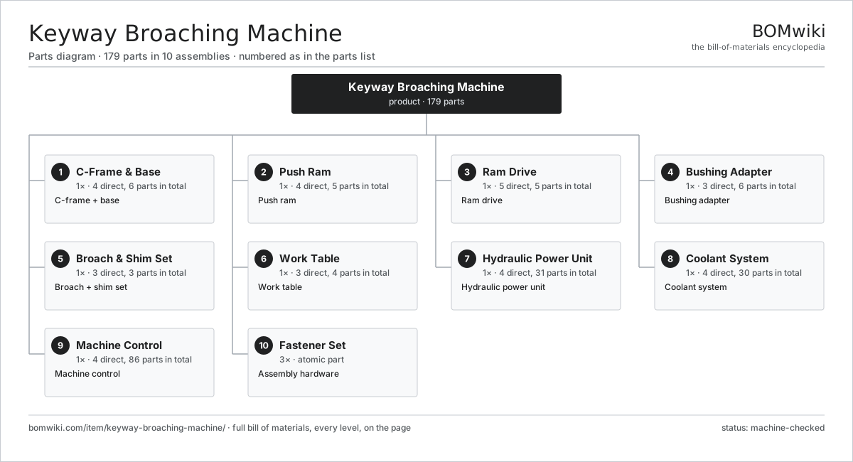
| # | Part | Qty | What it does |
|---|---|---|---|
| 1 | C-Frame & Base 4 parts | 1× | C-frame + base |
| 2 | Push Ram 4 parts | 1× | Push ram |
| 3 | Ram Drive 5 parts | 1× | Ram drive |
| 4 | Bushing Adapter 3 parts | 1× | Bushing adapter |
| 5 | Broach & Shim Set 3 parts | 1× | Broach + shim set |
| 6 | Work Table 3 parts | 1× | Work table |
| 7 | Hydraulic Power Unit 4 parts | 1× | Hydraulic power unit |
| 8 | Coolant System 4 parts | 1× | Coolant system |
| 9 | Machine Control 4 parts | 1× | Machine control |
| 10 | Fastener Set | 3× | Assembly hardware |
3D model
No 3D model yet. Have a CAD file of this? Add a 3D model — STL renders right on this page; STEP, FreeCAD, and OpenSCAD sources are welcome too (openly licensed, like all 3D models on BOMwiki).
Build & assembly graph
expand / collapse · shared sub-assemblies converge · links to related products · est. labourTap an assembly to expand/collapse · tap a part to open it · use “Open page” for any node · drag to pan, scroll to zoom.
Bill of materials for Keyway Broaching Machine
10 top-level lines · 58 rows shown · 179 parts total · indented to 3 levels| # | Item / sub-assembly | Part no. | Qty/assy | Ext. qty | Parts | Type |
|---|---|---|---|---|---|---|
| 1 | C-Frame & Base 4 parts | keyway-broaching-machine-frame | 1× | 1 | 6 | assembly |
| 1.1 | C-Frame Casting | keyway-broaching-machine-frame-casting | 1× | 1 | · | part |
| 1.2 | Base Casting | keyway-broaching-machine-base-casting | 1× | 1 | · | part |
| 1.3 | Ram Way | keyway-broaching-machine-way | 2× | 2 | · | part |
| 1.4 | Fastener Set | fastener-set | 2× | 2 | · | part |
| 2 | Push Ram 4 parts | keyway-broaching-machine-ram | 1× | 1 | 5 | assembly |
| 2.1 | Ram Body | keyway-broaching-machine-ram-body | 1× | 1 | · | part |
| 2.2 | Push Pad | keyway-broaching-machine-push-pad | 1× | 1 | · | part |
| 2.3 | Adjustable Gib | keyway-broaching-machine-gib | 2× | 2 | · | part |
| 2.4 | Stroke Scale | keyway-broaching-machine-scale | 1× | 1 | · | part |
| 3 | Ram Drive 5 parts | keyway-broaching-machine-drive | 1× | 1 | 5 | assembly |
| 3.1 | Main Cylinder | keyway-broaching-machine-cylinder | 1× | 1 | · | part |
| 3.2 | Piston Rod | piston-rod | 1× | 1 | · | part |
| 3.3 | Flow-Control Valve | keyway-broaching-machine-flow-valve | 1× | 1 | · | part |
| 3.4 | Pressure Sensor | pressure-sensor | 1× | 1 | · | part |
| 3.5 | O-Ring Set | oring-set | 1× | 1 | · | part |
| 4 | Bushing Adapter 3 parts | keyway-broaching-machine-adapter | 1× | 1 | 6 | assembly |
| 4.1 | Slotted Bushing | keyway-broaching-machine-bushing | 1× | 1 | · | part |
| 4.2 | Shim Plate | keyway-broaching-machine-bushing-shim | 4× | 4 | · | part |
| 4.3 | Bushing Collar | keyway-broaching-machine-collar | 1× | 1 | · | part |
| 5 | Broach & Shim Set 3 parts | keyway-broaching-machine-broach-set | 1× | 1 | 3 | assembly |
| 5.1 | Keyway Broach | keyway-broaching-machine-broach | 1× | 1 | · | part |
| 5.2 | Spline Broach | keyway-broaching-machine-spline-broach | 1× | 1 | · | part |
| 5.3 | Shim Pack | keyway-broaching-machine-shim-pack | 1× | 1 | · | part |
| 6 | Work Table 3 parts | keyway-broaching-machine-table | 1× | 1 | 4 | assembly |
| 6.1 | Table Plate | keyway-broaching-machine-table-plate | 1× | 1 | · | part |
| 6.2 | Vee Block | keyway-broaching-machine-vee-block | 2× | 2 | · | part |
| 6.3 | Hold-Down Clamp | keyway-broaching-machine-clamp | 1× | 1 | · | part |
| 7 | Hydraulic Power Unit 4 parts | keyway-broaching-machine-hydraulics | 1× | 1 | 31 | assembly |
| 7.1 | Main Pump 5 parts | keyway-broaching-machine-hyd-pump | 1× | 1 | 26 | assembly |
| 7.1.1 | Stator Assembly 3 parts + deeper › | stator-assembly | 1× | 1 | 3 | assembly |
| 7.1.2 | Rotor Assembly 4 parts + deeper › | rotor-assembly | 1× | 1 | 19 | assembly |
| 7.1.3 | Motor Housing | motor-housing | 1× | 1 | · | part |
| 7.1.4 | Ball Bearing | ball-bearing | 2× | 2 | · | part |
| 7.1.5 | Oil Seal | oil-seal | 1× | 1 | · | part |
| 7.2 | Oil Tank | keyway-broaching-machine-tank | 1× | 1 | · | part |
| 7.3 | Oil Cooler | keyway-broaching-machine-cooler | 1× | 1 | · | part |
| 7.4 | Relay | relay | 3× | 3 | · | part |
| 8 | Coolant System 4 parts | keyway-broaching-machine-coolant | 1× | 1 | 30 | assembly |
| 8.1 | Coolant Pump 5 parts | keyway-broaching-machine-coolant-pump | 1× | 1 | 26 | assembly |
| 8.1.1 | Stator Assembly 3 parts + deeper › | stator-assembly | 1× | 1 | 3 | assembly |
| 8.1.2 | Rotor Assembly 4 parts + deeper › | rotor-assembly | 1× | 1 | 19 | assembly |
| 8.1.3 | Motor Housing | motor-housing | 1× | 1 | · | part |
| 8.1.4 | Ball Bearing | ball-bearing | 2× | 2 | · | part |
| 8.1.5 | Oil Seal | oil-seal | 1× | 1 | · | part |
| 8.2 | Coolant Tank | coolant-tank | 1× | 1 | · | part |
| 8.3 | Coolant Nozzle | keyway-broaching-machine-nozzle | 1× | 1 | · | part |
| 8.4 | Coolant Hose | coolant-hose | 2× | 2 | · | part |
| 9 | Machine Control 4 parts | keyway-broaching-machine-control | 1× | 1 | 86 | assembly |
| 9.1 | PLC 4 parts | keyway-broaching-machine-plc | 1× | 1 | 76 | assembly |
| 9.1.1 | Bare PCB | pcb-bare | 1× | 1 | · | part |
| 9.1.2 | Microcontroller | mcu | 1× | 1 | · | part |
| 9.1.3 | Relay | relay | 4× | 4 | · | part |
| 9.1.4 | SMD Passive (R/C/L) | smd-passives | 70× | 70 | · | part |
| 9.2 | HMI Panel | hmi-panel | 1× | 1 | · | part |
| 9.3 | Wire Bundle | wire-bundle | 1× | 1 | · | part |
| 9.4 | Connector | connector | 8× | 8 | · | part |
| 10 | Fastener Set | fastener-set | 3× | 3 | · | part |
Related products
same domain, ranked by shared parts Surface Broaching Machine
219 parts · shares 5 with this page
Vertical Broaching Machine
220 parts · shares 5 with this page
Gear Shaving Machine
240 parts · shares 4 with this page
Surface Broaching Machine
219 parts · shares 5 with this page
Vertical Broaching Machine
220 parts · shares 5 with this page
Gear Shaving Machine
240 parts · shares 4 with this page
 Vertical Boring Mill
265 parts · shares 4 with this page
Vertical Boring Mill
265 parts · shares 4 with this page
 CNC Milling Machine
400 parts · shares 3 with this page
Gear Honing Machine
260 parts · shares 3 with this page
CNC Milling Machine
400 parts · shares 3 with this page
Gear Honing Machine
260 parts · shares 3 with this page
Sourcing: possible vendors
Prices, MOQ, and lead times are algorithmic estimates, not quotes, and not claims about these companies. Company mappings are curated by keyword; est. price band $10k–$1M. How estimates work| Vendor | HQ | Specialty | MOQ | Lead time |
|---|---|---|---|---|
|
🇩🇪DMG MORI
dmgmori.com ↗
|
Bielefeld, DE | Machine tools | 5 units | 12–20 wks |
|
🇯🇵Mazak
mazak.com ↗
|
Oguchi, JP | Machine tools | 5 units | 12–20 wks |
| haascnc.com ↗ | Oxnard, US | CNC machine tools | 5 units | 12–20 wks |
|
🇯🇵Okuma
okuma.com ↗
|
Niwa, JP | Machine tools | 5 units | 12–20 wks |
|
🇩🇪Trumpf
trumpf.com ↗
|
Ditzingen, DE | Laser & sheet-metal machines | 5 units | 12–20 wks |
879-word article