Airless Wheel Blast Machine
ProductOverview
An airless wheel blast machine cleans and conditions metal parts by throwing abrasive at them with spinning wheels rather than with compressed air. A motor turns a bladed wheel at a few thousand rpm, abrasive is metered into the centre, and centrifugal force flings the grit off the blade tips at sixty to eighty-five metres per second. The stream of steel shot or grit strips rust, scale, sand, old paint, and forging skin off the work, and with angular grit it also roughens the surface for coating. Because the wheel does the work mechanically, the machine uses far less energy than air blasting for the same throughput, which is why wheel blasting is the method of choice for high-volume cleaning of castings, forgings, plate, and structural steel.
The machine is built around the Blast Cabinet that contains the abrasive, one or more Throwing Wheel Unit assemblies that throw it, a Abrasive Circuit that recovers and cleans the abrasive for reuse, a Part Conveyor that moves parts through the blast zone, a Dust Collector that captures the dust, a Wheel Drive that spins the wheels, and a Control System that runs the cycle.
How the throwing wheel works
The Throwing Wheel Unit is the part that defines an airless machine. Abrasive drops through the Feed Spout into a small rotating Feed Impeller that sits inside a fixed Control Cage. The impeller flings grit outward, but it can only leave through the slot in the control cage, so the slot decides at what angle the abrasive meets the main blades. From there the grit lands on the Throwing Blade set carried by the Runner Plate, rides outward along the blade as the wheel spins, and leaves the blade tip in a tight fan aimed at the work. Rotating the control cage shifts that fan up or down the conveyor, which is how an operator aims a fixed wheel without moving the motor. The blades are the main consumable: they wear from the constant abrasive contact and are swapped using the Blade Lock wedges when the pattern starts to spread. The wheel shaft runs on a pair of Ball Bearing units inside the lined Wheel Housing.
Spinning the wheels
Each wheel is turned by its own Drive Motor, a three-phase machine with a Stator Assembly and Rotor Assembly sized for the abrasive throughput. The motor drives the wheel through a Drive Belt and a Motor Pulley, with the ratio chosen to set the rim speed, since abrasive velocity off the blade tips is fixed by how fast the blades move. The belt sits inside a Belt Guard. Wheel speed is held constant during the cycle because changing it would change the cleaning energy, so the work rate is set by abrasive flow rather than by speed.
Recovering and cleaning the abrasive
A wheel blast machine throws far more abrasive per minute than it consumes, so the Abrasive Circuit recovers nearly all of it. Spent grit and debris fall to the cabinet floor, where the Screw Conveyor augers drag it to the boot of the Bucket Elevator. The elevator lifts it on a chain of Elevator Bucket scoops to the Air Separator at the top of the machine. There the abrasive pours down as a thin Separator Curtain across an air stream: heavy reusable shot drops straight through, while light broken grit, dust, and scale are carried off to the dust collector. A Trash Screen catches oversize flash and fins before the clean abrasive falls into the Storage Hopper. From the hopper, a Flow Valve meters abrasive back to each wheel. Keeping the abrasive at a steady mix of sizes, called the operating mix, is what gives a repeatable finish, and the separator is what maintains it.
Containing the blast and the parts
The Blast Cabinet is a welded Cabinet Shell protected on the inside by bolt-in Wear Liner plates of manganese steel, which work-harden under impact and take the wear so the shell survives. Where parts enter and leave, Flap Curtain strips of rubber hang across the opening to keep ricocheting abrasive inside. Parts ride through on the Part Conveyor: in this roller type, a Roller Bed of hardened Conveyor Roller elements carries the work past the wheels. Parts pass in through the Entry Vestibule and out through the Exit Vestibule, where a blow-off knocks loose abrasive off the finished work before it leaves. Other machines use a rubber-belt tumble barrel for small loose parts, an overhead hanger for delicate or large work, or a rotary table for flat pieces, but the wheels, recovery, and dust systems are the same.
Dust collection and control
Blasting breaks abrasive and frees scale, so the Dust Collector keeps the cabinet under slight vacuum and pulls dust out of the air. The Exhaust Fan draws the airstream through a bank of Filter Cartridge elements, and each cartridge is cleaned in turn by a Pulse Valve that fires compressed air to shake the dust into the Dust Drum. A Pressure Sensor across the filters tells the controller when they are loading up. The Control System system, run by the PLC Module, sequences the wheels, the Flow Valve feeds, the conveyor, and the dust collector, and the operator sets cycle time and abrasive flow on the Operator Panel. A Ammeter on each wheel reads motor current, which rises with the amount of abrasive being thrown, so the operator can balance the wheels by load.
Use, abrasives, and limits
Wheel blast machines clean iron and steel castings, drop forgings, weldments, hot and cold rolled plate, structural sections, springs, fasteners, and rail. The abrasive is usually steel shot for a smooth peened surface or angular steel grit for a rough anchor profile under paint, with sizes from fine S110 up to coarse S660 chosen for the work. The limits come from the nature of airless blasting: the wheels throw in fixed directions, so shadowed pockets and deep bores may stay uncleaned, and very thin or soft parts can be dented or warped by the energy. The abrasive must be ferrous and tough enough to survive recovery, so soft media like glass bead or plastic are left to air-blast cabinets. Where line-of-sight access or gentle media matter more than throughput, an air blast room is used instead. Within its range the wheel blast machine remains the workhorse for high-volume surface preparation, cleaning tonnes of steel an hour at a fraction of the energy and air cost of pressure blasting.
Airless Wheel Blast Machine parts and their functions
7 top-level parts · 408 parts in total · full bill of materials below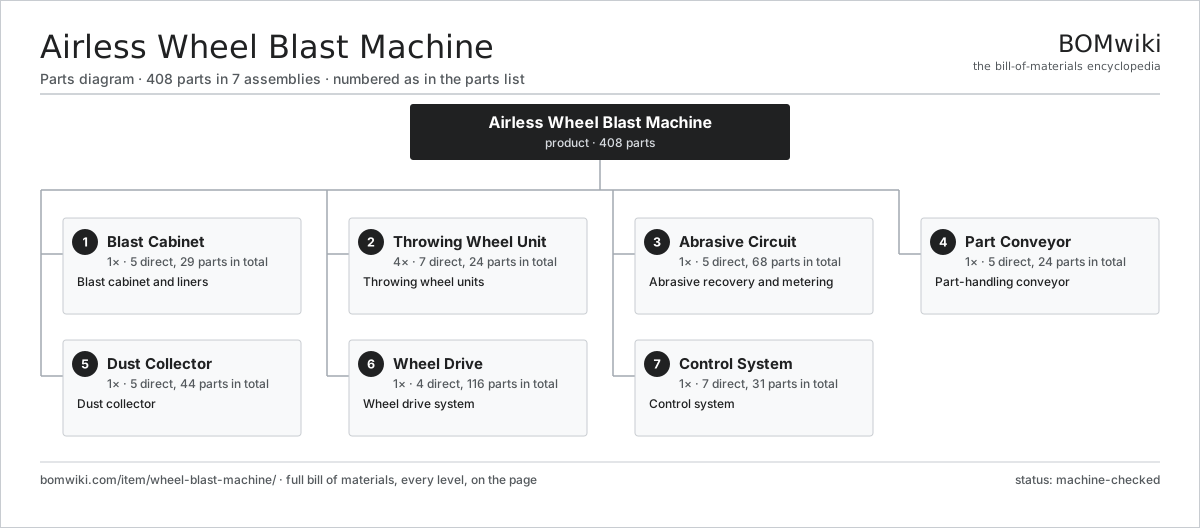
| # | Part | Qty | What it does |
|---|---|---|---|
| 1 | Blast Cabinet 5 parts | 1× | Blast cabinet and liners |
| 2 | Throwing Wheel Unit 7 parts | 4× | Throwing wheel units |
| 3 | Abrasive Circuit 5 parts | 1× | Abrasive recovery and metering |
| 4 | Part Conveyor 5 parts | 1× | Part-handling conveyor |
| 5 | Dust Collector 5 parts | 1× | Dust collector |
| 6 | Wheel Drive 4 parts | 1× | Wheel drive system |
| 7 | Control System 7 parts | 1× | Control system |
3D model
No 3D model yet. Have a CAD file of this? Add a 3D model — STL renders right on this page; STEP, FreeCAD, and OpenSCAD sources are welcome too (openly licensed, like all 3D models on BOMwiki).
Build & assembly graph
expand / collapse · shared sub-assemblies converge · links to related products · est. labourTap an assembly to expand/collapse · tap a part to open it · use “Open page” for any node · drag to pan, scroll to zoom.
Bill of materials for Airless Wheel Blast Machine
7 top-level lines · 72 rows shown · 408 parts total · indented to 3 levels| # | Item / sub-assembly | Part no. | Qty/assy | Ext. qty | Parts | Type |
|---|---|---|---|---|---|---|
| 1 | Blast Cabinet 5 parts | wheel-blast-machine-cabinet | 1× | 1 | 29 | assembly |
| 1.1 | Cabinet Shell | wheel-blast-machine-cabinet-shell | 1× | 1 | · | part |
| 1.2 | Wear Liner | wheel-blast-machine-wear-liner | 24× | 24 | · | part |
| 1.3 | Flap Curtain | wheel-blast-machine-flap-curtain | 2× | 2 | · | part |
| 1.4 | Access Door | wheel-blast-machine-access-door | 1× | 1 | · | part |
| 1.5 | Fastener Set | fastener-set | 1× | 1 | · | part |
| 2 | Throwing Wheel Unit 7 parts | wheel-blast-machine-wheel-unit | 4× | 4 | 24 | assembly |
| 2.1 | Wheel Housing | wheel-blast-machine-wheel-housing | 1× | 4 | · | part |
| 2.2 | Runner Plate 2 parts | wheel-blast-machine-runner-plate | 1× | 4 | 10 | assembly |
| 2.2.1 | Runner Disc | wheel-blast-machine-runner-disc | 2× | 8 | · | part |
| 2.2.2 | Blade Lock | wheel-blast-machine-blade-lock | 8× | 32 | · | part |
| 2.3 | Throwing Blade | wheel-blast-machine-throwing-blade | 8× | 32 | · | part |
| 2.4 | Feed Impeller | wheel-blast-machine-impeller | 1× | 4 | · | part |
| 2.5 | Control Cage | wheel-blast-machine-control-cage | 1× | 4 | · | part |
| 2.6 | Feed Spout | wheel-blast-machine-feed-spout | 1× | 4 | · | part |
| 2.7 | Ball Bearing | ball-bearing | 2× | 8 | · | part |
| 3 | Abrasive Circuit 5 parts | wheel-blast-machine-abrasive-circuit | 1× | 1 | 68 | assembly |
| 3.1 | Screw Conveyor 4 parts | wheel-blast-machine-screw-conveyor | 1× | 1 | 11 | assembly |
| 3.1.1 | Screw Auger | wheel-blast-machine-screw-auger | 2× | 2 | · | part |
| 3.1.2 | Trough Liner | wheel-blast-machine-trough-liner | 4× | 4 | · | part |
| 3.1.3 | Gearbox Housing | gearbox-housing | 1× | 1 | · | part |
| 3.1.4 | Ball Bearing | ball-bearing | 4× | 4 | · | part |
| 3.2 | Bucket Elevator 4 parts | wheel-blast-machine-bucket-elevator | 1× | 1 | 47 | assembly |
| 3.2.1 | Elevator Belt | wheel-blast-machine-elevator-belt | 1× | 1 | · | part |
| 3.2.2 | Elevator Bucket | wheel-blast-machine-elevator-bucket | 40× | 40 | · | part |
| 3.2.3 | Elevator Pulley | wheel-blast-machine-elevator-pulley | 2× | 2 | · | part |
| 3.2.4 | Ball Bearing | ball-bearing | 4× | 4 | · | part |
| 3.3 | Air Separator 3 parts | wheel-blast-machine-air-separator | 1× | 1 | 5 | assembly |
| 3.3.1 | Separator Curtain | wheel-blast-machine-separator-curtain | 1× | 1 | · | part |
| 3.3.2 | Separator Baffle | wheel-blast-machine-separator-baffle | 3× | 3 | · | part |
| 3.3.3 | Trash Screen | wheel-blast-machine-trash-screen | 1× | 1 | · | part |
| 3.4 | Storage Hopper | wheel-blast-machine-storage-hopper | 1× | 1 | · | part |
| 3.5 | Flow Valve | wheel-blast-machine-flow-valve | 4× | 4 | · | part |
| 4 | Part Conveyor 5 parts | wheel-blast-machine-conveyor | 1× | 1 | 24 | assembly |
| 4.1 | Roller Bed | wheel-blast-machine-roller-bed | 1× | 1 | · | part |
| 4.2 | Conveyor Roller | wheel-blast-machine-conveyor-roller | 20× | 20 | · | part |
| 4.3 | Entry Vestibule | wheel-blast-machine-entry-vestibule | 1× | 1 | · | part |
| 4.4 | Exit Vestibule | wheel-blast-machine-exit-vestibule | 1× | 1 | · | part |
| 4.5 | Drive Belt | drive-belt | 1× | 1 | · | part |
| 5 | Dust Collector 5 parts | wheel-blast-machine-dust-collector | 1× | 1 | 44 | assembly |
| 5.1 | Filter Cartridge | wheel-blast-machine-filter-cartridge | 8× | 8 | · | part |
| 5.2 | Pulse Valve | wheel-blast-machine-pulse-valve | 8× | 8 | · | part |
| 5.3 | Exhaust Fan 5 parts | wheel-blast-machine-dust-fan | 1× | 1 | 26 | assembly |
| 5.3.1 | Fan Impeller | wheel-blast-machine-fan-impeller | 1× | 1 | · | part |
| 5.3.2 | Fan Scroll | wheel-blast-machine-fan-scroll | 1× | 1 | · | part |
| 5.3.3 | Stator Assembly 3 parts + deeper › | stator-assembly | 1× | 1 | 3 | assembly |
| 5.3.4 | Rotor Assembly 4 parts + deeper › | rotor-assembly | 1× | 1 | 19 | assembly |
| 5.3.5 | Ball Bearing | ball-bearing | 2× | 2 | · | part |
| 5.4 | Dust Drum | wheel-blast-machine-dust-drum | 1× | 1 | · | part |
| 5.5 | Pressure Sensor | pressure-sensor | 1× | 1 | · | part |
| 6 | Wheel Drive 4 parts | wheel-blast-machine-drive | 1× | 1 | 116 | assembly |
| 6.1 | Drive Motor 4 parts | wheel-blast-machine-drive-motor | 4× | 4 | 26 | assembly |
| 6.1.1 | Stator Assembly 3 parts + deeper › | stator-assembly | 1× | 4 | 3 | assembly |
| 6.1.2 | Rotor Assembly 4 parts + deeper › | rotor-assembly | 1× | 4 | 19 | assembly |
| 6.1.3 | Ball Bearing | ball-bearing | 2× | 8 | · | part |
| 6.1.4 | Oil Seal | oil-seal | 2× | 8 | · | part |
| 6.2 | Drive Belt | drive-belt | 4× | 4 | · | part |
| 6.3 | Motor Pulley | wheel-blast-machine-motor-pulley | 4× | 4 | · | part |
| 6.4 | Belt Guard | wheel-blast-machine-belt-guard | 4× | 4 | · | part |
| 7 | Control System 7 parts | wheel-blast-machine-control | 1× | 1 | 31 | assembly |
| 7.1 | PLC Module 3 parts | wheel-blast-machine-plc | 1× | 1 | 3 | assembly |
| 7.1.1 | Bare PCB | pcb-bare | 1× | 1 | · | part |
| 7.1.2 | Microcontroller | mcu | 1× | 1 | · | part |
| 7.1.3 | SMD Passive (R/C/L) | smd-passives | 1× | 1 | · | part |
| 7.2 | Operator Panel 2 parts | wheel-blast-machine-operator-panel | 1× | 1 | 2 | assembly |
| 7.2.1 | LCD Panel | lcd-panel | 1× | 1 | · | part |
| 7.2.2 | Membrane Keypad | wheel-blast-machine-membrane-keypad | 1× | 1 | · | part |
| 7.3 | Ammeter | wheel-blast-machine-amp-meter | 4× | 4 | · | part |
| 7.4 | Relay | relay | 8× | 8 | · | part |
| 7.5 | Power Supply | power-supply | 1× | 1 | · | part |
| 7.6 | Wire Bundle | wire-bundle | 1× | 1 | · | part |
| 7.7 | Connector | connector | 12× | 12 | · | part |
Related products
same domain, ranked by shared parts Bevel Gear Generator
201 parts · shares 3 with this page
Bevel Gear Generator
201 parts · shares 3 with this page
 Creep-Feed Grinder
571 parts · shares 3 with this page
Double-Disc Grinder
153 parts · shares 3 with this page
Drag Finishing Machine
735 parts · shares 3 with this page
Multi-Blanking Line
492 parts · shares 3 with this page
Creep-Feed Grinder
571 parts · shares 3 with this page
Double-Disc Grinder
153 parts · shares 3 with this page
Drag Finishing Machine
735 parts · shares 3 with this page
Multi-Blanking Line
492 parts · shares 3 with this page
 Multi-Spindle Automatic Lathe
352 parts · shares 3 with this page
Multi-Spindle Automatic Lathe
352 parts · shares 3 with this page
Sourcing: possible vendors
Prices, MOQ, and lead times are algorithmic estimates, not quotes, and not claims about these companies. Company mappings are curated by keyword; est. price band $10k–$1M. How estimates work| Vendor | HQ | Specialty | MOQ | Lead time |
|---|---|---|---|---|
|
🇩🇪DMG MORI
dmgmori.com ↗
|
Bielefeld, DE | Machine tools | 5 units | 12–20 wks |
|
🇯🇵Mazak
mazak.com ↗
|
Oguchi, JP | Machine tools | 5 units | 12–20 wks |
| haascnc.com ↗ | Oxnard, US | CNC machine tools | 5 units | 12–20 wks |
|
🇯🇵Okuma
okuma.com ↗
|
Niwa, JP | Machine tools | 5 units | 12–20 wks |
|
🇩🇪Trumpf
trumpf.com ↗
|
Ditzingen, DE | Laser & sheet-metal machines | 5 units | 12–20 wks |
1,217-word article