Hydraulic Punch Press
ProductOverview
A hydraulic punch press shears holes and cutouts in sheet metal by forcing a hardened Cutting Punch through the workpiece into a matching Die Button. Unlike a mechanical press, which stores energy in a flywheel and delivers a fixed stroke, the hydraulic press generates force through pressurized oil acting on a piston. That gives it full force anywhere in the stroke, adjustable speed and depth, and a controllable dwell at the bottom of the stroke. The trade-off is a slower cycle, so hydraulic punch presses are favored for thick plate, varied tooling, and short runs rather than high-volume stamping.
The machine is built around an open-throat C-Frame Structure that carries the reaction load when the punch shears the sheet. Pressurized oil from the Hydraulic Power Unit drives the Main Punching Cylinder, which pushes the guided Ram Slide down through the sheet supported on the Bolster Table. A Stripper Assembly holds the sheet flat and pulls it off the punch on the return. The whole sequence is run by a Control System and fenced by a Safety System.
Frame and Force Path
The Frame Weldment is a stress-relieved steel plate weldment, 60 to 100 mm thick in the loaded sections, machined flat where the cylinder and bolster bolt on. An open C-frame is convenient because sheets can be fed from three sides, but the open throat tends to spring open under load, which tips the punch and widens the burr. To control that, the frame uses pre-tensioned Frame Tie Rod members that pull the throat closed, and the ram rides on adjustable Ram Gib strips that keep it square to the bolster. Frame deflection is held to a small fraction of a millimeter at rated tonnage so the punch-to-die clearance stays uniform around the cut.
Hydraulic Power Unit
The Hydraulic Power Unit is a self-contained oil station. A Pump Drive Motor of 15 to 45 kW drives a Variable Piston Pump, a load-sensing axial-piston pump that supplies only the flow the stroke needs, which keeps the oil cool and saves energy between hits. Oil is drawn from the Oil Reservoir, a baffled steel tank of 200 to 500 L with a sight glass and breather. A pilot-operated Main Relief Valve caps system pressure at 250 bar so an overload cannot damage the cylinder or frame. A Bladder Accumulator stores oil to give a fast return stroke and to supply peak flow during the punch, and an Oil Cooler rejects pump heat to hold reservoir temperature below 55°C. A Return Line Filter keeps the oil clean, which is the single biggest factor in valve and pump life.
Cylinder and Ram
Force is generated in the Main Punching Cylinder. A hard-chrome Piston and Rod runs in a honed Cylinder Barrel of 120 to 200 mm bore, sized so that the piston area multiplied by 250 bar meets the rated tonnage. The Cylinder Seal Kit uses a polyurethane rod seal and a PTFE piston seal, both rated for the full pressure. The piston rod bolts to the Ram Body, a box-section ram that carries the upper tooling and is guided by the frame gibs. A linear Stroke Encoder reports ram position to ±0.05 mm, and an adjustable Depth Stop sets the bottom of the stroke so the punch enters the die by a consistent depth.
Tooling and Stripping
The actual cut happens at the Tooling Station. The Cutting Punch is a tool-steel punch hardened to 58 to 62 HRC and ground to the hole profile; a shear angle on its face spreads the cut over time and lowers the peak force. The matching Die Button is set with a clearance of 5 to 10 percent of the sheet thickness, the parameter that decides how clean the sheared edge is. Punch and die are kept concentric by ground Guide Pin members riding in bushings. After the cut, the Stripper Plate backed by Coil Spring elements holds the sheet down and strips it off the punch as the ram lifts, while the slug drops through the Die Button into the Scrap Chute.
Control and Safety
The Control System is built on a safety PLC Module that sequences a Proportional Valve for stroke speed and dwell and two Directional Valve units for advance and return. The operator works from an HMI Touch Panel that holds job setups, tonnage readout and diagnostics. Because the die area is a serious crush and shear hazard, the Safety System guards it with a Type 4 Safety Light Curtain, requires an anti-tie-down Two-Hand Control to start each stroke, and routes every E-Stop Station through a dual-channel Safety Relay rated to PL e. Any interruption drops the valve solenoids and the ram stops.
Variants and Use
Punch presses range from small 30 ton benchtop units making electrical enclosure cutouts to 300 ton machines blanking thick plate for structural brackets. Turret variants carry many tools in an indexing head for CNC hole patterns, while single-station hydraulic presses like this one are common in fabrication shops for ironwork, perforating and notching. Compared with a Mechanical Power Press, the hydraulic press is slower but more flexible: it can pause at depth, vary force, and is far harder to jam on overload because the relief valve simply opens. That makes it the standard choice for thick material, frequent tool changes, and jobs where overload protection matters more than raw cycle speed.
Hydraulic Punch Press parts and their functions
9 top-level parts · 348 parts in total · full bill of materials below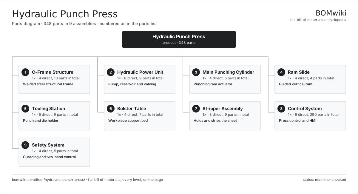
| # | Part | Qty | What it does |
|---|---|---|---|
| 1 | C-Frame Structure 4 parts | 1× | Welded steel structural frame |
| 2 | Hydraulic Power Unit 8 parts | 1× | Pump, reservoir and valving |
| 3 | Main Punching Cylinder 4 parts | 1× | Punching ram actuator |
| 4 | Ram Slide 4 parts | 1× | Guided vertical ram |
| 5 | Tooling Station 5 parts | 1× | Punch and die holder |
| 6 | Bolster Table 4 parts | 1× | Workpiece support bed |
| 7 | Stripper Assembly 3 parts | 1× | Holds and strips the sheet |
| 8 | Control System 6 parts | 1× | Press control and HMI |
| 9 | Safety System 4 parts | 1× | Guarding and two-hand control |
3D model
No 3D model yet. Have a CAD file of this? Add a 3D model — STL renders right on this page; STEP, FreeCAD, and OpenSCAD sources are welcome too (openly licensed, like all 3D models on BOMwiki).
Build & assembly graph
expand / collapse · shared sub-assemblies converge · links to related products · est. labourTap an assembly to expand/collapse · tap a part to open it · use “Open page” for any node · drag to pan, scroll to zoom.
Bill of materials for Hydraulic Punch Press
9 top-level lines · 64 rows shown · 348 parts total · indented to 3 levels| # | Item / sub-assembly | Part no. | Qty/assy | Ext. qty | Parts | Type |
|---|---|---|---|---|---|---|
| 1 | C-Frame Structure 4 parts | hpp-c-frame | 1× | 1 | 10 | assembly |
| 1.1 | Frame Weldment | hpp-frame-weldment | 1× | 1 | · | part |
| 1.2 | Frame Tie Rod | hpp-tie-rod | 4× | 4 | · | part |
| 1.3 | Ram Gib | hpp-ram-gib | 4× | 4 | · | part |
| 1.4 | Fastener Set | fastener-set | 1× | 1 | · | part |
| 2 | Hydraulic Power Unit 8 parts | hpp-hydraulic-power-unit | 1× | 1 | 9 | assembly |
| 2.1 | Variable Piston Pump | hpp-hydraulic-pump | 1× | 1 | · | part |
| 2.2 | Pump Drive Motor | hpp-pump-motor | 1× | 1 | · | part |
| 2.3 | Oil Reservoir | hpp-oil-reservoir | 1× | 1 | · | part |
| 2.4 | Main Relief Valve | hpp-relief-valve | 1× | 1 | · | part |
| 2.5 | Return Line Filter | hpp-return-filter | 1× | 1 | · | part |
| 2.6 | Bladder Accumulator | hpp-accumulator | 1× | 1 | · | part |
| 2.7 | Oil Cooler | hpp-oil-cooler | 1× | 1 | · | part |
| 2.8 | Pressure Sensor | pressure-sensor | 2× | 2 | · | part |
| 3 | Main Punching Cylinder 4 parts | hpp-main-cylinder | 1× | 1 | 5 | assembly |
| 3.1 | Cylinder Barrel | hpp-cylinder-tube | 1× | 1 | · | part |
| 3.2 | Piston and Rod | hpp-cylinder-piston | 1× | 1 | · | part |
| 3.3 | Cylinder Seal Kit | hpp-cylinder-seal-kit | 1× | 1 | · | part |
| 3.4 | Cylinder End Cap | hpp-cylinder-end-cap | 2× | 2 | · | part |
| 4 | Ram Slide 4 parts | hpp-ram-slide | 1× | 1 | 4 | assembly |
| 4.1 | Ram Body | hpp-ram-body | 1× | 1 | · | part |
| 4.2 | Punch Adapter Plate | hpp-punch-adapter | 1× | 1 | · | part |
| 4.3 | Stroke Encoder | hpp-stroke-encoder | 1× | 1 | · | part |
| 4.4 | Depth Stop | hpp-depth-stop | 1× | 1 | · | part |
| 5 | Tooling Station 5 parts | hpp-tooling-station | 1× | 1 | 9 | assembly |
| 5.1 | Cutting Punch | hpp-punch | 1× | 1 | · | part |
| 5.2 | Die Button | hpp-die-button | 1× | 1 | · | part |
| 5.3 | Punch Holder | hpp-punch-holder | 1× | 1 | · | part |
| 5.4 | Guide Pin | hpp-guide-pin | 2× | 2 | · | part |
| 5.5 | Ball Bearing | ball-bearing | 4× | 4 | · | part |
| 6 | Bolster Table 4 parts | hpp-bolster-table | 1× | 1 | 7 | assembly |
| 6.1 | Bolster Plate | hpp-bolster-plate | 1× | 1 | · | part |
| 6.2 | Back Gauge | hpp-back-gauge | 1× | 1 | · | part |
| 6.3 | Scrap Chute | hpp-scrap-chute | 1× | 1 | · | part |
| 6.4 | Die Clamp | hpp-die-clamp | 4× | 4 | · | part |
| 7 | Stripper Assembly 3 parts | hpp-stripper-assembly | 1× | 1 | 9 | assembly |
| 7.1 | Stripper Plate | hpp-stripper-plate | 1× | 1 | · | part |
| 7.2 | Coil Spring | coil-spring | 4× | 4 | · | part |
| 7.3 | Stripper Bolt | hpp-stripper-bolt | 4× | 4 | · | part |
| 8 | Control System 6 parts | hpp-control-system | 1× | 1 | 290 | assembly |
| 8.1 | PLC Module 4 parts | hpp-plc-module | 1× | 1 | 151 | assembly |
| 8.1.1 | Bare PCB | pcb-bare | 1× | 1 | · | part |
| 8.1.2 | Microcontroller | mcu | 2× | 2 | · | part |
| 8.1.3 | Relay | relay | 8× | 8 | · | part |
| 8.1.4 | SMD Passive (R/C/L) | smd-passives | 140× | 140 | · | part |
| 8.2 | Proportional Valve | hpp-proportional-valve | 1× | 1 | · | part |
| 8.3 | Directional Valve | hpp-directional-valve | 2× | 2 | · | part |
| 8.4 | HMI Touch Panel 9 parts | hmi-touch-panel | 1× | 1 | 134 | product |
| 8.4.1 | Touchscreen Assembly 4 parts + deeper › | hmi-touch-panel-display | 1× | 1 | 4 | assembly |
| 8.4.2 | CPU / SoC Module 5 parts + deeper › | hmi-touch-panel-cpu | 1× | 1 | 84 | assembly |
| 8.4.3 | Storage and Flash 3 parts + deeper › | hmi-touch-panel-memory | 1× | 1 | 3 | assembly |
| 8.4.4 | Fieldbus / Network Interface 3 parts + deeper › | hmi-touch-panel-fieldbus | 1× | 1 | 22 | assembly |
| 8.4.5 | Industrial Power Supply 4 parts + deeper › | hmi-touch-panel-power | 1× | 1 | 4 | assembly |
| 8.4.6 | Backlight LED Driver 3 parts + deeper › | hmi-touch-panel-backlight | 1× | 1 | 3 | assembly |
| 8.4.7 | Heat Dissipation 3 parts + deeper › | hmi-touch-panel-cooling | 1× | 1 | 3 | assembly |
| 8.4.8 | Front Panel Bezel 4 parts + deeper › | hmi-touch-panel-bezel | 1× | 1 | 4 | assembly |
| 8.4.9 | Cabinet Mounting Hardware 4 parts + deeper › | hmi-touch-panel-mounting | 1× | 1 | 7 | assembly |
| 8.5 | Power Supply | power-supply | 1× | 1 | · | part |
| 8.6 | Wire Bundle | wire-bundle | 1× | 1 | · | part |
| 9 | Safety System 4 parts | hpp-safety-system | 1× | 1 | 5 | assembly |
| 9.1 | Safety Light Curtain | hpp-light-curtain | 1× | 1 | · | part |
| 9.2 | Two-Hand Control | hpp-two-hand-control | 1× | 1 | · | part |
| 9.3 | E-Stop Station | hpp-estop-station | 2× | 2 | · | part |
| 9.4 | Safety Relay | hpp-safety-relay | 1× | 1 | · | part |
Related products
same domain, ranked by shared parts Compression Spring Coiler
1,167 parts · shares 2 with this page
Compression Spring Coiler
1,167 parts · shares 2 with this page
 Honing Machine
325 parts · shares 2 with this page
Honing Machine
325 parts · shares 2 with this page
 Servo Stamping Press
633 parts · shares 2 with this page
Servo Stamping Press
633 parts · shares 2 with this page
Sourcing: possible vendors
Prices, MOQ, and lead times are algorithmic estimates, not quotes, and not claims about these companies. Company mappings are curated by keyword; est. price band $10k–$1M. How estimates work| Vendor | HQ | Specialty | MOQ | Lead time |
|---|---|---|---|---|
|
🇩🇪DMG MORI
dmgmori.com ↗
|
Bielefeld, DE | Machine tools | 5 units | 12–20 wks |
|
🇯🇵Mazak
mazak.com ↗
|
Oguchi, JP | Machine tools | 5 units | 12–20 wks |
| haascnc.com ↗ | Oxnard, US | CNC machine tools | 5 units | 12–20 wks |
|
🇯🇵Okuma
okuma.com ↗
|
Niwa, JP | Machine tools | 5 units | 12–20 wks |
|
🇩🇪Trumpf
trumpf.com ↗
|
Ditzingen, DE | Laser & sheet-metal machines | 5 units | 12–20 wks |
949-word article