Vertical Machining Center
ProductOverview
A vertical machining center, usually shortened to VMC, is the workhorse of a modern machine shop. It is an enclosed CNC milling machine whose spindle points straight down, so the cutting tool plunges and traverses across a workpiece clamped to a horizontal table below. Under computer control it can drill, mill pockets, contour surfaces, tap threads, and bore holes, swapping tools automatically between operations. A single VMC can take a block of aluminum or steel and turn it into a finished part with several faces machined in one setup. Sizes range from compact machines with a half-meter of X travel suited to small molds and electronics housings, up to large units with 1.3 meters of travel handling aerospace structural parts.
The machine is built around eight major systems. The Base and Column Structure is the cast iron skeleton holding everything in fixed geometric relationship. The Spindle Head carries the rotating tool. The Axis Feed Drives move the table and spindle along three linear axes. The Automatic Tool Changer swaps tools without operator intervention. The Worktable holds the work. The Coolant System cools and flushes the cut. The Machine Enclosure contains chips and protects the operator. The Control Cabinet runs the program and drives the motors.
Structure and rigidity
Accuracy in milling comes from rigidity. When a tool removes metal it pushes back on the spindle with hundreds of newtons of force, and any flex in the structure shows up as error in the finished part. The Cast Iron Base and Column are heavy gray cast iron castings, ribbed inside and stress-relieved so they hold shape over years. Cast iron is chosen because it damps vibration better than welded steel and machines to a fine reference surface. The Saddle rides on the base to give cross-axis motion, and the whole machine sits on Leveling Foot that let an installer bring the table level to within a few microns per meter. Telescoping Way Cover panels keep abrasive chips off the precision guideways.
The spindle
The Spindle Head converts motor power into a precisely rotating, precisely located cutting tool. At its center is the Spindle Cartridge, a hardened steel shaft preloaded in a stack of angular contact Ball Bearing units and ground to run with sub-micron radial error. The Spindle Motor drives it, often through a Drive Belt for lower speeds and direct coupling at high speed, delivering constant power across the working range. A Drawbar uses a Belleville Coil Spring stack to pull the tool holder into the Spindle Taper with 8-15 kN, locking it concentric to the spindle axis. A Spindle Encoder reports angular position so the control can perform rigid tapping, where spindle rotation and Z feed are synchronized to cut a thread without a floating tap holder.
Motion: axes and feedback
The three linear axes are driven by the Axis Feed Drives. Each axis uses a Servo Motor turning a ground Ball Screw through a zero-backlash Bellows Coupling, converting rotation into linear motion. The moving members ride on recirculating Linear Guide Rail rails that carry load with almost no friction or stick-slip. Position is closed back to the control either by the motor encoder or, on accurate machines, by a Linear Scale mounted directly on the axis that measures real slide position to a couple of microns regardless of screw wear or thermal growth. A Lubrication Pump meters oil or grease to the screws and guides on a timed cycle so they never run dry. Rapid traverse rates of 24-48 m/min let the machine move quickly between cuts, while feed rates during cutting are set by the program to suit the material.
Tool changing and automation
What separates a machining center from a manual mill is the Automatic Tool Changer. A Tool Carousel holds 20-40 tools in numbered Tool Pocket forks. When the program calls a new tool, the ATC Drive indexes the carousel to present it, and a cam-driven Tool Change Arm swings to grip both the spindle tool and the magazine tool at once, pulling one out and inserting the other in a single rotation. Chip-to-chip change times of a few seconds mean a part needing a dozen tools loses little time to tool swaps. The control stores a length and diameter offset for each tool so the cutting geometry stays correct no matter which tool is loaded.
Coolant, chips, and enclosure
Cutting metal generates heat and swarf. The Coolant System manages both. A Flood Pump floods the cut from articulated Coolant Nozzle outlets, while a Through-Spindle Pump can push coolant at 20-70 bar through the spindle and out the tool tip to clear deep holes. Coolant drains to the Coolant Tank through a Coolant Filter, and chips are carried out by a Chip Conveyor. The Machine Enclosure surrounds the work zone in folded Sheet Metal Panel guards with a Access Door window of laminated polycarbonate. A Door Interlock stops the spindle if the door opens during a cycle.
Control and use
The Control Cabinet is where G-code becomes motion. The CNC Control interprets the program, a Servo Amplifier drives each motor, and a Machine PLC sequences tool changes, coolant, and safety logic. The operator works at the Operator Panel with its LCD Panel screen and uses a Handwheel to jog axes during setup. VMCs are used everywhere from job shops making one-off prototypes to production lines machining engine components, mold and die work, medical implants, and aerospace brackets. Their combination of three-axis flexibility, automatic tool changing, and moderate cost makes them the default first machine in most metalworking shops.
Vertical Machining Center parts and their functions
8 top-level parts · 195 parts in total · full bill of materials below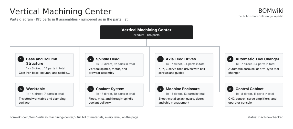
| # | Part | Qty | What it does |
|---|---|---|---|
| 1 | Base and Column Structure 6 parts | 1× | Cast iron base, column, and saddle structure |
| 2 | Spindle Head 8 parts | 1× | Vertical spindle, motor, and drawbar assembly |
| 3 | Axis Feed Drives 7 parts | 1× | X, Y, Z servo feed drives with ball screws and guides |
| 4 | Automatic Tool Changer 7 parts | 1× | Automatic carousel or arm-type tool changer |
| 5 | Worktable 4 parts | 1× | T-slotted worktable and clamping surface |
| 6 | Coolant System 7 parts | 1× | Flood, mist, and through-spindle coolant delivery |
| 7 | Machine Enclosure 5 parts | 1× | Sheet-metal splash guard, doors, and chip management |
| 8 | Control Cabinet 8 parts | 1× | CNC control, servo amplifiers, and operator console |
3D model
No 3D model yet. Have a CAD file of this? Add a 3D model — STL renders right on this page; STEP, FreeCAD, and OpenSCAD sources are welcome too (openly licensed, like all 3D models on BOMwiki).
Build & assembly graph
expand / collapse · shared sub-assemblies converge · links to related products · est. labourTap an assembly to expand/collapse · tap a part to open it · use “Open page” for any node · drag to pan, scroll to zoom.
Bill of materials for Vertical Machining Center
8 top-level lines · 64 rows shown · 195 parts total · indented to 3 levels| # | Item / sub-assembly | Part no. | Qty/assy | Ext. qty | Parts | Type |
|---|---|---|---|---|---|---|
| 1 | Base and Column Structure 6 parts | vmc-base-column | 1× | 1 | 14 | assembly |
| 1.1 | Cast Iron Base | vmc-cast-base | 1× | 1 | · | part |
| 1.2 | Column | vmc-column | 1× | 1 | · | part |
| 1.3 | Saddle | vmc-saddle | 1× | 1 | · | part |
| 1.4 | Leveling Foot | vmc-leveling-feet | 6× | 6 | · | part |
| 1.5 | Way Cover | vmc-way-cover | 4× | 4 | · | part |
| 1.6 | Fastener Set | fastener-set | 1× | 1 | · | part |
| 2 | Spindle Head 8 parts | vmc-spindle-head | 1× | 1 | 12 | assembly |
| 2.1 | Spindle Cartridge | vmc-spindle-cartridge | 1× | 1 | · | part |
| 2.2 | Spindle Motor | vmc-spindle-motor | 1× | 1 | · | part |
| 2.3 | Drawbar | vmc-drawbar | 1× | 1 | · | part |
| 2.4 | Spindle Taper | vmc-tool-taper | 1× | 1 | · | part |
| 2.5 | Drive Belt | drive-belt | 1× | 1 | · | part |
| 2.6 | Ball Bearing | ball-bearing | 4× | 4 | · | part |
| 2.7 | Oil Seal | oil-seal | 2× | 2 | · | part |
| 2.8 | Spindle Encoder | vmc-spindle-encoder | 1× | 1 | · | part |
| 3 | Axis Feed Drives 7 parts | vmc-axis-drives | 1× | 1 | 94 | assembly |
| 3.1 | Servo Motor 4 parts | servo-motor | 3× | 3 | 24 | assembly |
| 3.1.1 | Stator Assembly 3 parts + deeper › | stator-assembly | 1× | 3 | 3 | assembly |
| 3.1.2 | Rotor Assembly 4 parts + deeper › | rotor-assembly | 1× | 3 | 19 | assembly |
| 3.1.3 | Encoder | encoder | 1× | 3 | · | part |
| 3.1.4 | Motor Housing | motor-housing | 1× | 3 | · | part |
| 3.2 | Ball Screw | ball-screw | 3× | 3 | · | part |
| 3.3 | Linear Guide Rail | linear-guide | 6× | 6 | · | part |
| 3.4 | Bellows Coupling | vmc-coupling | 3× | 3 | · | part |
| 3.5 | Linear Scale | vmc-linear-scale | 3× | 3 | · | part |
| 3.6 | Ball Bearing | ball-bearing | 6× | 6 | · | part |
| 3.7 | Lubrication Pump | vmc-lube-pump | 1× | 1 | · | part |
| 4 | Automatic Tool Changer 7 parts | vmc-tool-changer | 1× | 1 | 34 | assembly |
| 4.1 | Tool Carousel | vmc-tool-carousel | 1× | 1 | · | part |
| 4.2 | Tool Change Arm | vmc-changer-arm | 1× | 1 | · | part |
| 4.3 | ATC Drive | vmc-atc-motor | 1× | 1 | · | part |
| 4.4 | Tool Pocket | vmc-tool-pocket | 24× | 24 | · | part |
| 4.5 | Helical Gear Pair | gear-pair | 1× | 1 | · | part |
| 4.6 | Ball Bearing | ball-bearing | 4× | 4 | · | part |
| 4.7 | Relay | relay | 2× | 2 | · | part |
| 5 | Worktable 4 parts | vmc-table | 1× | 1 | 7 | assembly |
| 5.1 | Table Casting | vmc-table-casting | 1× | 1 | · | part |
| 5.2 | Table Wiper | vmc-table-wiper | 4× | 4 | · | part |
| 5.3 | Chip Tray | vmc-chip-tray | 1× | 1 | · | part |
| 5.4 | Fastener Set | fastener-set | 1× | 1 | · | part |
| 6 | Coolant System 7 parts | vmc-coolant-system | 1× | 1 | 10 | assembly |
| 6.1 | Coolant Tank | vmc-coolant-tank | 1× | 1 | · | part |
| 6.2 | Flood Pump | vmc-flood-pump | 1× | 1 | · | part |
| 6.3 | Through-Spindle Pump | vmc-tsc-pump | 1× | 1 | · | part |
| 6.4 | Coolant Nozzle | vmc-coolant-nozzle | 4× | 4 | · | part |
| 6.5 | Chip Conveyor | vmc-chip-conveyor | 1× | 1 | · | part |
| 6.6 | Coolant Filter | vmc-coolant-filter | 1× | 1 | · | part |
| 6.7 | O-Ring Set | oring-set | 1× | 1 | · | part |
| 7 | Machine Enclosure 5 parts | vmc-enclosure | 1× | 1 | 13 | assembly |
| 7.1 | Sheet Metal Panel | sheet-panel | 6× | 6 | · | part |
| 7.2 | Access Door | vmc-door | 2× | 2 | · | part |
| 7.3 | Door Interlock | vmc-door-interlock | 2× | 2 | · | part |
| 7.4 | Work Light | vmc-work-light | 2× | 2 | · | part |
| 7.5 | Fastener Set | fastener-set | 1× | 1 | · | part |
| 8 | Control Cabinet 8 parts | vmc-control-cabinet | 1× | 1 | 11 | assembly |
| 8.1 | CNC Control | vmc-cnc-control | 1× | 1 | · | part |
| 8.2 | Servo Amplifier | vmc-servo-amp | 4× | 4 | · | part |
| 8.3 | Operator Panel | vmc-operator-panel | 1× | 1 | · | part |
| 8.4 | Power Supply | power-supply | 1× | 1 | · | part |
| 8.5 | Machine PLC | vmc-plc | 1× | 1 | · | part |
| 8.6 | Handwheel | vmc-handwheel | 1× | 1 | · | part |
| 8.7 | LCD Panel | lcd-panel | 1× | 1 | · | part |
| 8.8 | Wire Bundle | wire-bundle | 1× | 1 | · | part |
Related products
same domain, ranked by shared parts Horizontal Machining Center
240 parts · shares 8 with this page
Horizontal Machining Center
240 parts · shares 8 with this page
 Five-Axis Machining Center
168 parts · shares 8 with this page
Five-Axis Machining Center
168 parts · shares 8 with this page
 Bed-Type Milling Machine
151 parts · shares 7 with this page
Gantry Milling Machine
198 parts · shares 6 with this page
Bar Chamfering Machine
1,148 parts · shares 8 with this page
Bed-Type Milling Machine
151 parts · shares 7 with this page
Gantry Milling Machine
198 parts · shares 6 with this page
Bar Chamfering Machine
1,148 parts · shares 8 with this page
 Crankshaft Grinder
511 parts · shares 8 with this page
Crankshaft Grinder
511 parts · shares 8 with this page
Sourcing: possible vendors
Prices, MOQ, and lead times are algorithmic estimates, not quotes, and not claims about these companies. Company mappings are curated by keyword; est. price band $10k–$1M. How estimates work| Vendor | HQ | Specialty | MOQ | Lead time |
|---|---|---|---|---|
|
🇩🇪DMG MORI
dmgmori.com ↗
|
Bielefeld, DE | Machine tools | 5 units | 12–20 wks |
|
🇯🇵Mazak
mazak.com ↗
|
Oguchi, JP | Machine tools | 5 units | 12–20 wks |
| haascnc.com ↗ | Oxnard, US | CNC machine tools | 5 units | 12–20 wks |
|
🇯🇵Okuma
okuma.com ↗
|
Niwa, JP | Machine tools | 5 units | 12–20 wks |
|
🇩🇪Trumpf
trumpf.com ↗
|
Ditzingen, DE | Laser & sheet-metal machines | 5 units | 12–20 wks |
971-word article