Quench Tank System
ProductOverview
A quench tank system rapidly cools metal parts after they leave a furnace, fixing the microstructure that gives the parts their hardness and strength. When steel is heated and then cooled fast enough, the iron does not have time to revert to its soft form and instead transforms to hard martensite. The quench tank is the equipment that delivers that fast, controlled, and repeatable cooling. The hard part is not making metal cold but making it cool at the right rate everywhere on the part at once, because uneven cooling causes soft spots, cracks, and distortion. The system controls the cooling rate through the choice of fluid, its temperature, and how hard it is pumped past the load.
The system centers on a Tank Body holding the quenchant, an Agitation System system that moves the fluid, a Cooling Loop loop that pulls heat back out between loads, a Heating System system for cold starts, an Elevator and Basket that immerses the load, an Quenchant System system that keeps the quenchant in spec, a Control System system, and an Safety System system for the fire and fume hazards.
The tank and flow path
The Tank Body is a welded Tank Shell sized so that the heat from one load raises the bulk fluid temperature only a few degrees. Inside, a Draft Tube channels pumped fluid straight up past the part, and a Baffle Set of Flow Baffle plates and a Diffuser Plate diffuser spread the flow so it is even across the whole basket. An Overflow Weir weir holds the level and skims the surface to the cooling loop, a Drain Valve empties the tank at fluid change, and a Tank Cover limits evaporation and helps smother a surface fire. Even flow matters because a part that cools faster on one side than the other will warp or crack.
Agitation
Agitation sets the severity of the quench, so the Agitation System system is the heart of the design. Marine-type Agitator Impeller propellers on Agitator Shaft shafts, driven by Agitator Motor motors, push the fluid through the draft tube and past the load. The faster the flow, the faster the part cools, because moving fluid strips away the insulating vapor blanket that forms on hot metal in oil or polymer. A Variable Frequency Drive varies the agitator speed during the quench, which lets the operator follow a profile: hard agitation at first to break the vapor stage, then slower flow during the slower-cooling phase to limit distortion. This control over the cooling curve is what separates a quench tank system from a plain bucket of oil.
Cooling and heating
Each load dumps a large amount of heat into the fluid, so the Cooling Loop loop pulls it back out. A Circulation Pump, built from a Pump Casing, Pump Impeller, and Pump Motor, drives fluid through a Heat Exchanger whose Tube Bundle inside the Exchanger Shell transfers heat to cooling water, with a Quenchant Filter removing scale and a Cooling Water Valve modulating the water. Holding bath temperature steady keeps the cooling behavior repeatable from load to load. The Heating System system does the opposite job at startup: a set of Immersion Heater elements, watched by a Heater Thermostat, warms cold quenchant to operating temperature, because cold oil is thick and quenches differently from oil at its normal working temperature.
Loading and fluid care
The Elevator and Basket lowers the load fast and evenly into the fluid. An Elevator Frame guided by Guide Rail rails carries a Load Basket of parts, raised and dropped by a Lift Hoist whose Hoist Motor turns a Cable Drum and Lift Cable lines. A fast, square entry matters because a part that enters tilted or slowly cools unevenly. The Quenchant System system keeps the quenchant healthy with a Surface Skimmer that removes tramp oil and, for water-polymer baths, a Concentration Sensor that tracks the Quenchant concentration, since a polymer that drifts off concentration changes the cooling rate.
Media, control, and safety
The quench medium is chosen for the alloy and the section size. Fast oils and water-polymer solutions cool quickly for plain and low-alloy steels, while slow marquenching oils cool gently for parts prone to cracking. The Control System system uses a PLC reading Temperature Sensor and Level Sensor inputs through a Operator Panel panel to hold temperature and run the agitation profile. Safety is built in because hot oil above its flash point and a load that pulls partly clear of the fluid can ignite. The Safety System system pairs a Fire Suppression release of agent through Discharge Nozzle outlets with a Fume Hood that captures quench smoke and Fire Sensor detectors that trigger suppression. Within those bounds the quench tank system serves forge shops, foundries, and heat-treat lines wherever parts must be hardened in volume with a predictable result.
Quench Tank System parts and their functions
8 top-level parts · 93 parts in total · full bill of materials below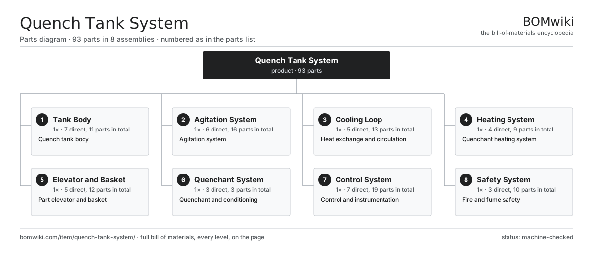
| # | Part | Qty | What it does |
|---|---|---|---|
| 1 | Tank Body 7 parts | 1× | Quench tank body |
| 2 | Agitation System 6 parts | 1× | Agitation system |
| 3 | Cooling Loop 5 parts | 1× | Heat exchange and circulation |
| 4 | Heating System 4 parts | 1× | Quenchant heating system |
| 5 | Elevator and Basket 5 parts | 1× | Part elevator and basket |
| 6 | Quenchant System 3 parts | 1× | Quenchant and conditioning |
| 7 | Control System 7 parts | 1× | Control and instrumentation |
| 8 | Safety System 3 parts | 1× | Fire and fume safety |
3D model
No 3D model yet. Have a CAD file of this? Add a 3D model — STL renders right on this page; STEP, FreeCAD, and OpenSCAD sources are welcome too (openly licensed, like all 3D models on BOMwiki).
Build & assembly graph
expand / collapse · shared sub-assemblies converge · links to related products · est. labourTap an assembly to expand/collapse · tap a part to open it · use “Open page” for any node · drag to pan, scroll to zoom.
Bill of materials for Quench Tank System
8 top-level lines · 77 rows shown · 93 parts total · indented to 3 levels| # | Item / sub-assembly | Part no. | Qty/assy | Ext. qty | Parts | Type |
|---|---|---|---|---|---|---|
| 1 | Tank Body 7 parts | quench-tank-system-tank | 1× | 1 | 11 | assembly |
| 1.1 | Tank Shell | quench-tank-system-shell | 1× | 1 | · | part |
| 1.2 | Draft Tube | quench-tank-system-draft-tube | 1× | 1 | · | part |
| 1.3 | Baffle Set 2 parts | quench-tank-system-baffle-set | 1× | 1 | 5 | assembly |
| 1.3.1 | Flow Baffle | quench-tank-system-flow-baffle | 4× | 4 | · | part |
| 1.3.2 | Diffuser Plate | quench-tank-system-perforated-plate | 1× | 1 | · | part |
| 1.4 | Overflow Weir | quench-tank-system-overflow | 1× | 1 | · | part |
| 1.5 | Drain Valve | quench-tank-system-drain | 1× | 1 | · | part |
| 1.6 | Tank Cover | quench-tank-system-cover | 1× | 1 | · | part |
| 1.7 | Fastener Set | fastener-set | 1× | 1 | · | part |
| 2 | Agitation System 6 parts | quench-tank-system-agitation | 1× | 1 | 16 | assembly |
| 2.1 | Agitator Impeller | quench-tank-system-impeller | 2× | 2 | · | part |
| 2.2 | Agitator Shaft | quench-tank-system-agitator-shaft | 2× | 2 | · | part |
| 2.3 | Agitator Motor | quench-tank-system-agitator-motor | 2× | 2 | · | part |
| 2.4 | Variable Frequency Drive 4 parts | quench-tank-system-vfd | 1× | 1 | 4 | assembly |
| 2.4.1 | Bare PCB | pcb-bare | 1× | 1 | · | part |
| 2.4.2 | Microcontroller | mcu | 1× | 1 | · | part |
| 2.4.3 | SMD Passive (R/C/L) | smd-passives | 1× | 1 | · | part |
| 2.4.4 | Power Supply | power-supply | 1× | 1 | · | part |
| 2.5 | Ball Bearing | ball-bearing | 4× | 4 | · | part |
| 2.6 | Oil Seal | oil-seal | 2× | 2 | · | part |
| 3 | Cooling Loop 5 parts | quench-tank-system-cooling | 1× | 1 | 13 | assembly |
| 3.1 | Circulation Pump 5 parts | quench-tank-system-circ-pump | 1× | 1 | 6 | assembly |
| 3.1.1 | Pump Casing | quench-tank-system-pump-casing | 1× | 1 | · | part |
| 3.1.2 | Pump Impeller | quench-tank-system-pump-impeller | 1× | 1 | · | part |
| 3.1.3 | Pump Motor | quench-tank-system-pump-motor | 1× | 1 | · | part |
| 3.1.4 | Ball Bearing | ball-bearing | 2× | 2 | · | part |
| 3.1.5 | Oil Seal | oil-seal | 1× | 1 | · | part |
| 3.2 | Heat Exchanger 3 parts | quench-tank-system-heat-exchanger | 1× | 1 | 3 | assembly |
| 3.2.1 | Exchanger Shell | quench-tank-system-exchanger-shell | 1× | 1 | · | part |
| 3.2.2 | Tube Bundle | quench-tank-system-tube-bundle | 1× | 1 | · | part |
| 3.2.3 | O-Ring Set | oring-set | 1× | 1 | · | part |
| 3.3 | Quenchant Filter | quench-tank-system-filter | 1× | 1 | · | part |
| 3.4 | Cooling Water Valve | quench-tank-system-cooling-valve | 2× | 2 | · | part |
| 3.5 | Pressure Sensor | pressure-sensor | 1× | 1 | · | part |
| 4 | Heating System 4 parts | quench-tank-system-heating | 1× | 1 | 9 | assembly |
| 4.1 | Immersion Heater | quench-tank-system-immersion-heater | 3× | 3 | · | part |
| 4.2 | Heater Thermostat | quench-tank-system-heater-thermostat | 1× | 1 | · | part |
| 4.3 | Heating Element | heating-element | 3× | 3 | · | part |
| 4.4 | Relay | relay | 2× | 2 | · | part |
| 5 | Elevator and Basket 5 parts | quench-tank-system-elevator | 1× | 1 | 12 | assembly |
| 5.1 | Elevator Frame | quench-tank-system-elevator-frame | 1× | 1 | · | part |
| 5.2 | Lift Hoist 5 parts | quench-tank-system-hoist | 1× | 1 | 6 | assembly |
| 5.2.1 | Hoist Motor | quench-tank-system-hoist-motor | 1× | 1 | · | part |
| 5.2.2 | Cable Drum | quench-tank-system-hoist-drum | 1× | 1 | · | part |
| 5.2.3 | Lift Cable | quench-tank-system-hoist-cable | 2× | 2 | · | part |
| 5.2.4 | Helical Gear Pair | gear-pair | 1× | 1 | · | part |
| 5.2.5 | Gearbox Housing | gearbox-housing | 1× | 1 | · | part |
| 5.3 | Load Basket | quench-tank-system-basket | 1× | 1 | · | part |
| 5.4 | Guide Rail | quench-tank-system-guide-rail | 2× | 2 | · | part |
| 5.5 | Linear Guide Rail | linear-guide | 2× | 2 | · | part |
| 6 | Quenchant System 3 parts | quench-tank-system-fluid | 1× | 1 | 3 | assembly |
| 6.1 | Quenchant | quench-tank-system-quench-oil | 1× | 1 | · | part |
| 6.2 | Surface Skimmer | quench-tank-system-skimmer | 1× | 1 | · | part |
| 6.3 | Concentration Sensor | quench-tank-system-refractometer | 1× | 1 | · | part |
| 7 | Control System 7 parts | quench-tank-system-control | 1× | 1 | 19 | assembly |
| 7.1 | PLC 4 parts | quench-tank-system-plc | 1× | 1 | 7 | assembly |
| 7.1.1 | Bare PCB | pcb-bare | 1× | 1 | · | part |
| 7.1.2 | Microcontroller | mcu | 1× | 1 | · | part |
| 7.1.3 | SMD Passive (R/C/L) | smd-passives | 1× | 1 | · | part |
| 7.1.4 | Relay | relay | 4× | 4 | · | part |
| 7.2 | Temperature Sensor | quench-tank-system-temp-sensor | 2× | 2 | · | part |
| 7.3 | Level Sensor | quench-tank-system-level-sensor | 1× | 1 | · | part |
| 7.4 | Operator Panel 3 parts | quench-tank-system-hmi | 1× | 1 | 3 | assembly |
| 7.4.1 | LCD Panel | lcd-panel | 1× | 1 | · | part |
| 7.4.2 | Bare PCB | pcb-bare | 1× | 1 | · | part |
| 7.4.3 | Microcontroller | mcu | 1× | 1 | · | part |
| 7.5 | Power Supply | power-supply | 1× | 1 | · | part |
| 7.6 | Wire Bundle | wire-bundle | 1× | 1 | · | part |
| 7.7 | Connector | connector | 4× | 4 | · | part |
| 8 | Safety System 3 parts | quench-tank-system-safety | 1× | 1 | 10 | assembly |
| 8.1 | Fire Suppression 3 parts | quench-tank-system-fire-suppression | 1× | 1 | 7 | assembly |
| 8.1.1 | Agent Cylinder | quench-tank-system-suppression-cylinder | 2× | 2 | · | part |
| 8.1.2 | Discharge Nozzle | quench-tank-system-suppression-nozzle | 4× | 4 | · | part |
| 8.1.3 | Release Valve | quench-tank-system-suppression-valve | 1× | 1 | · | part |
| 8.2 | Fume Hood | quench-tank-system-fume-hood | 1× | 1 | · | part |
| 8.3 | Fire Sensor | quench-tank-system-fire-sensor | 2× | 2 | · | part |
Related products
same domain, ranked by shared parts Rotary-Table Surface Grinder
172 parts · shares 6 with this page
Rotary-Table Surface Grinder
172 parts · shares 6 with this page
 Continuous Belt Furnace
130 parts · shares 5 with this page
Continuous Belt Furnace
130 parts · shares 5 with this page
 Crankshaft Grinder
511 parts · shares 5 with this page
Crankshaft Grinder
511 parts · shares 5 with this page
 Profile Grinding Machine
815 parts · shares 4 with this page
Sealed Quench Furnace
185 parts · shares 4 with this page
Profile Grinding Machine
815 parts · shares 4 with this page
Sealed Quench Furnace
185 parts · shares 4 with this page
 Aluminum Extrusion Press
365 parts · shares 4 with this page
Aluminum Extrusion Press
365 parts · shares 4 with this page
Sourcing: possible vendors
Prices, MOQ, and lead times are algorithmic estimates, not quotes, and not claims about these companies. Company mappings are curated by keyword; est. price band $10k–$1M. How estimates work| Vendor | HQ | Specialty | MOQ | Lead time |
|---|---|---|---|---|
|
🇩🇪DMG MORI
dmgmori.com ↗
|
Bielefeld, DE | Machine tools | 5 units | 12–20 wks |
|
🇯🇵Mazak
mazak.com ↗
|
Oguchi, JP | Machine tools | 5 units | 12–20 wks |
| haascnc.com ↗ | Oxnard, US | CNC machine tools | 5 units | 12–20 wks |
|
🇯🇵Okuma
okuma.com ↗
|
Niwa, JP | Machine tools | 5 units | 12–20 wks |
|
🇩🇪Trumpf
trumpf.com ↗
|
Ditzingen, DE | Laser & sheet-metal machines | 5 units | 12–20 wks |
951-word article