Tool & Cutter Grinder
ProductAlso known as: Tool and Cutter Grinder
Overview
A tool and cutter grinder resharpens the cutting edges of other tools: end mills, slot drills, twist drills, reamers, taps, hobs and form cutters all come back to it once they go dull. Sharpening means grinding a small, exact amount off a cutting edge to restore its rake, relief and clearance angles, so the machine is built to hold the tool at a precise angle and present each tooth to the wheel in the same place. This is a universal type: the Workhead grips and indexes the tool, the Swivel Wheelhead tilts and swivels to any approach angle, and the Tooth Rest locates each tooth so successive teeth grind identically.
Everything mounts on the Base, Saddle & Table. A cast iron base damps the vibration that would otherwise chatter into a keen edge, and a stacked Cross Saddle and Swivel Table ride hardened, hand-scraped ways. The table swivels in plan, which is how a straight pass past the wheel grinds the helical relief on a milling cutter.
How it works
The operator fits the tool into the Workhead: shank tools go into a collet from the Collet Set, while arbor-mounted cutters are carried between the workhead and the Tailstock on centres. The Swivel Wheelhead is set to the angle the edge needs by tilting and swivelling it on its Swivel & Tilt Mount, and wheel height is set with the Wheelhead Height Screw. The Tooth Rest is then adjusted so its blade lightly touches the back of one tooth.
Sharpening is done one tooth at a time. With the tooth resting on the Tooth Rest Blade, the operator feeds the table past the wheel using the Cross & Longitudinal Feeds, grinding that tooth. The tool is then rotated by hand until the next tooth drops onto the rest blade, and the pass is repeated. Because the tooth rest fixes the radial position of whichever tooth is being ground, every tooth ends up at the same height and the cutter stays concentric. For fluted cutters that need accurate division, the Indexing Plate in the workhead detents the spindle to a set number of positions, and the Spindle Detent Lock holds it there.
Wheelhead and wheels
The Swivel Wheelhead runs a double-ended Wheel Spindle so two wheels can be mounted, one on each nose, and selected by swivelling the head rather than changing wheels. The spindle is reversible, which matters because a wheel should cut so that its rotation pushes the edge onto the work rather than away from it. The Spindle Cartridge carries the arbors on angular-contact Ball Bearing sets, and a Spindle Motor built from a Stator Assembly and Rotor Assembly drives it. Different jobs call for different wheels from the Wheel Set: a Cup Wheel grinds flat faces, a Dish Wheel reaches into flutes and gullets without the wheel body fouling the next tooth, and a Plain Wheel handles general peripheral relief.
Workholding and indexing
The Workhead is the part that makes the machine universal. Its body swivels so the tool axis can be set at any angle to the wheel, and its spindle runs on Ball Bearing supports so the tool turns smoothly under hand pressure during a relief pass. The Tailstock backs up long or arbor-mounted work with a spring-loaded Dead Centre that keeps centre pressure as the work is fed. Together with the indexing plate, this setup lets one machine sharpen everything from a four-flute end mill to a multi-tooth form cutter without special fixturing.
Dust, coolant and control
Carbide and HSS grinding throw off fine dust that is both a health hazard and an abrasive that wears slides, so the Dust Extraction & Coolant system pulls dry dust through a Filter Cartridge filter. For carbide tooling that is ground wet, the same module runs a Coolant Pump feeding a Coolant Nozzle at the contact point and a Coolant Filter cleaning the returning fluid. The Control & Display sequences spindle start, direction and on powered models the Power Feed Unit traverse.
Variants and use
Manual universal grinders like this one rely on the operator and the tooth rest for accuracy and are the workhorse of any toolroom that resharpens its own cutters. At the top end the same machine concept goes fully CNC: five controlled axes replace the hand feeds and the tooth rest, the control turns the tool and tracks each flute from a geometry program, and the machine grinds a whole end mill from solid carbide blank to finished tool in one cycle. Production tool manufacturers run those CNC versions, while repair shops and toolrooms keep manual grinders for one-off resharpening of milling cutters, drills, reamers and the odd form tool.
Tool & Cutter Grinder parts and their functions
10 top-level parts · 242 parts in total · full bill of materials below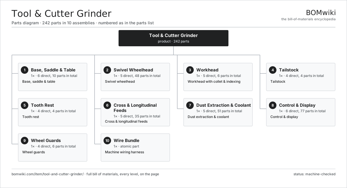
| # | Part | Qty | What it does |
|---|---|---|---|
| 1 | Base, Saddle & Table 6 parts | 1× | Base, saddle & table |
| 2 | Swivel Wheelhead 5 parts | 1× | Swivel wheelhead |
| 3 | Workhead 5 parts | 1× | Workhead with collet & indexing |
| 4 | Tailstock 4 parts | 1× | Tailstock |
| 5 | Tooth Rest 4 parts | 1× | Tooth rest |
| 6 | Cross & Longitudinal Feeds 5 parts | 1× | Cross & longitudinal feeds |
| 7 | Dust Extraction & Coolant 5 parts | 1× | Dust extraction & coolant |
| 8 | Control & Display 6 parts | 1× | Control & display |
| 9 | Wheel Guards 4 parts | 1× | Wheel guards |
| 10 | Wire Bundle | 1× | Machine wiring harness |
3D model
No 3D model yet. Have a CAD file of this? Add a 3D model — STL renders right on this page; STEP, FreeCAD, and OpenSCAD sources are welcome too (openly licensed, like all 3D models on BOMwiki).
Build & assembly graph
expand / collapse · shared sub-assemblies converge · links to related products · est. labourTap an assembly to expand/collapse · tap a part to open it · use “Open page” for any node · drag to pan, scroll to zoom.
Bill of materials for Tool & Cutter Grinder
10 top-level lines · 78 rows shown · 242 parts total · indented to 3 levels| # | Item / sub-assembly | Part no. | Qty/assy | Ext. qty | Parts | Type |
|---|---|---|---|---|---|---|
| 1 | Base, Saddle & Table 6 parts | tool-and-cutter-grinder-base | 1× | 1 | 10 | assembly |
| 1.1 | Base Casting | tool-and-cutter-grinder-base-casting | 1× | 1 | · | part |
| 1.2 | Cross Saddle | tool-and-cutter-grinder-saddle | 1× | 1 | · | part |
| 1.3 | Swivel Table | tool-and-cutter-grinder-table | 1× | 1 | · | part |
| 1.4 | Hardened Slideway | tool-and-cutter-grinder-slideway | 2× | 2 | · | part |
| 1.5 | Way Wiper | tool-and-cutter-grinder-way-wiper | 4× | 4 | · | part |
| 1.6 | Fastener Set | fastener-set | 1× | 1 | · | part |
| 2 | Swivel Wheelhead 5 parts | tool-and-cutter-grinder-wheelhead | 1× | 1 | 48 | assembly |
| 2.1 | Wheelhead Body | tool-and-cutter-grinder-wheelhead-body | 1× | 1 | · | part |
| 2.2 | Swivel & Tilt Mount 3 parts | tool-and-cutter-grinder-swivel-mount | 1× | 1 | 4 | assembly |
| 2.2.1 | Swivel Base | tool-and-cutter-grinder-swivel-base | 1× | 1 | · | part |
| 2.2.2 | Clamp Lever | tool-and-cutter-grinder-clamp-lever | 2× | 2 | · | part |
| 2.2.3 | Helical Gear Pair | gear-pair | 1× | 1 | · | part |
| 2.3 | Wheel Spindle 4 parts | tool-and-cutter-grinder-spindle | 1× | 1 | 39 | assembly |
| 2.3.1 | Spindle Motor 5 parts + deeper › | tool-and-cutter-grinder-spindle-motor | 1× | 1 | 26 | assembly |
| 2.3.2 | Spindle Cartridge 4 parts + deeper › | tool-and-cutter-grinder-spindle-cartridge | 1× | 1 | 10 | assembly |
| 2.3.3 | Wheel Flange | tool-and-cutter-grinder-wheel-flange | 2× | 2 | · | part |
| 2.3.4 | Spindle Quill | tool-and-cutter-grinder-quill | 1× | 1 | · | part |
| 2.4 | Wheel Set 3 parts | tool-and-cutter-grinder-wheel-set | 1× | 1 | 3 | assembly |
| 2.4.1 | Cup Wheel | tool-and-cutter-grinder-cup-wheel | 1× | 1 | · | part |
| 2.4.2 | Dish Wheel | tool-and-cutter-grinder-dish-wheel | 1× | 1 | · | part |
| 2.4.3 | Plain Wheel | tool-and-cutter-grinder-plain-wheel | 1× | 1 | · | part |
| 2.5 | Wheelhead Height Screw | tool-and-cutter-grinder-height-screw | 1× | 1 | · | part |
| 3 | Workhead 5 parts | tool-and-cutter-grinder-workhead | 1× | 1 | 6 | assembly |
| 3.1 | Workhead Body | tool-and-cutter-grinder-workhead-body | 1× | 1 | · | part |
| 3.2 | Collet Set | tool-and-cutter-grinder-collet-set | 1× | 1 | · | part |
| 3.3 | Indexing Plate | tool-and-cutter-grinder-index-plate | 1× | 1 | · | part |
| 3.4 | Spindle Detent Lock | tool-and-cutter-grinder-spindle-lock | 1× | 1 | · | part |
| 3.5 | Ball Bearing | ball-bearing | 2× | 2 | · | part |
| 4 | Tailstock 4 parts | tool-and-cutter-grinder-tailstock | 1× | 1 | 4 | assembly |
| 4.1 | Tailstock Body | tool-and-cutter-grinder-tailstock-body | 1× | 1 | · | part |
| 4.2 | Dead Centre | tool-and-cutter-grinder-centre | 1× | 1 | · | part |
| 4.3 | Spring Centre Sleeve | tool-and-cutter-grinder-tailstock-spring | 1× | 1 | · | part |
| 4.4 | Coil Spring | coil-spring | 1× | 1 | · | part |
| 5 | Tooth Rest 4 parts | tool-and-cutter-grinder-tooth-rest | 1× | 1 | 4 | assembly |
| 5.1 | Tooth Rest Arm | tool-and-cutter-grinder-tooth-rest-arm | 1× | 1 | · | part |
| 5.2 | Tooth Rest Blade | tool-and-cutter-grinder-tooth-blade | 1× | 1 | · | part |
| 5.3 | Tooth Rest Clamp | tool-and-cutter-grinder-rest-clamp | 1× | 1 | · | part |
| 5.4 | Coil Spring | coil-spring | 1× | 1 | · | part |
| 6 | Cross & Longitudinal Feeds 5 parts | tool-and-cutter-grinder-feeds | 1× | 1 | 35 | assembly |
| 6.1 | Cross-Feed Screw | tool-and-cutter-grinder-cross-screw | 1× | 1 | · | part |
| 6.2 | Longitudinal Screw | tool-and-cutter-grinder-long-screw | 1× | 1 | · | part |
| 6.3 | Graduated Handwheel | tool-and-cutter-grinder-handwheel | 2× | 2 | · | part |
| 6.4 | Power Feed Unit 3 parts | tool-and-cutter-grinder-power-feed | 1× | 1 | 27 | assembly |
| 6.4.1 | Servo Motor 4 parts + deeper › | servo-motor | 1× | 1 | 24 | assembly |
| 6.4.2 | Helical Gear Pair | gear-pair | 1× | 1 | · | part |
| 6.4.3 | Ball Bearing | ball-bearing | 2× | 2 | · | part |
| 6.5 | Ball Bearing | ball-bearing | 4× | 4 | · | part |
| 7 | Dust Extraction & Coolant 5 parts | tool-and-cutter-grinder-extraction | 1× | 1 | 51 | assembly |
| 7.1 | Dust Extractor 4 parts | tool-and-cutter-grinder-extractor | 1× | 1 | 24 | assembly |
| 7.1.1 | Stator Assembly 3 parts + deeper › | stator-assembly | 1× | 1 | 3 | assembly |
| 7.1.2 | Rotor Assembly 4 parts + deeper › | rotor-assembly | 1× | 1 | 19 | assembly |
| 7.1.3 | Motor Housing | motor-housing | 1× | 1 | · | part |
| 7.1.4 | Filter Cartridge | tool-and-cutter-grinder-extractor-cartridge | 1× | 1 | · | part |
| 7.2 | Coolant Pump 4 parts | tool-and-cutter-grinder-coolant-pump | 1× | 1 | 24 | assembly |
| 7.2.1 | Stator Assembly 3 parts + deeper › | stator-assembly | 1× | 1 | 3 | assembly |
| 7.2.2 | Rotor Assembly 4 parts + deeper › | rotor-assembly | 1× | 1 | 19 | assembly |
| 7.2.3 | Motor Housing | motor-housing | 1× | 1 | · | part |
| 7.2.4 | Oil Seal | oil-seal | 1× | 1 | · | part |
| 7.3 | Coolant Tank | tool-and-cutter-grinder-coolant-tank | 1× | 1 | · | part |
| 7.4 | Coolant Nozzle | tool-and-cutter-grinder-nozzle | 1× | 1 | · | part |
| 7.5 | Coolant Filter | tool-and-cutter-grinder-filter | 1× | 1 | · | part |
| 8 | Control & Display 6 parts | tool-and-cutter-grinder-control | 1× | 1 | 77 | assembly |
| 8.1 | Control Board 3 parts | tool-and-cutter-grinder-control-board | 1× | 1 | 62 | assembly |
| 8.1.1 | Bare PCB | pcb-bare | 1× | 1 | · | part |
| 8.1.2 | Microcontroller | mcu | 1× | 1 | · | part |
| 8.1.3 | SMD Passive (R/C/L) | smd-passives | 60× | 60 | · | part |
| 8.2 | LCD Panel | lcd-panel | 1× | 1 | · | part |
| 8.3 | Relay | relay | 4× | 4 | · | part |
| 8.4 | Connector | connector | 8× | 8 | · | part |
| 8.5 | Power Supply | power-supply | 1× | 1 | · | part |
| 8.6 | Control Enclosure | tool-and-cutter-grinder-enclosure | 1× | 1 | · | part |
| 9 | Wheel Guards 4 parts | tool-and-cutter-grinder-guard | 1× | 1 | 6 | assembly |
| 9.1 | Wheel Guard | tool-and-cutter-grinder-wheel-guard | 2× | 2 | · | part |
| 9.2 | Dust Shroud | tool-and-cutter-grinder-shroud | 1× | 1 | · | part |
| 9.3 | Sheet Metal Panel | sheet-panel | 2× | 2 | · | part |
| 9.4 | Fastener Set | fastener-set | 1× | 1 | · | part |
| 10 | Wire Bundle | wire-bundle | 1× | 1 | · | part |
Related products
same domain, ranked by shared parts Compression Spring Coiler
1,167 parts · shares 5 with this page
Compression Spring Coiler
1,167 parts · shares 5 with this page
 Crankshaft Grinder
511 parts · shares 5 with this page
Crankshaft Grinder
511 parts · shares 5 with this page
 Creep-Feed Grinder
571 parts · shares 5 with this page
Creep-Feed Grinder
571 parts · shares 5 with this page
Sourcing: possible vendors
Prices, MOQ, and lead times are algorithmic estimates, not quotes, and not claims about these companies. Company mappings are curated by keyword; est. price band $10k–$1M. How estimates work| Vendor | HQ | Specialty | MOQ | Lead time |
|---|---|---|---|---|
|
🇩🇪DMG MORI
dmgmori.com ↗
|
Bielefeld, DE | Machine tools | 5 units | 12–20 wks |
|
🇯🇵Mazak
mazak.com ↗
|
Oguchi, JP | Machine tools | 5 units | 12–20 wks |
| haascnc.com ↗ | Oxnard, US | CNC machine tools | 5 units | 12–20 wks |
|
🇯🇵Okuma
okuma.com ↗
|
Niwa, JP | Machine tools | 5 units | 12–20 wks |
|
🇩🇪Trumpf
trumpf.com ↗
|
Ditzingen, DE | Laser & sheet-metal machines | 5 units | 12–20 wks |
901-word article