Roll Grinding Machine
ProductOverview
A roll grinding machine restores the working rolls and backup rolls of metal rolling mills. In a hot or cold rolling mill, large steel rolls squeeze slabs and strip to thickness, and those rolls wear, pick up surface defects, and lose their carefully shaped crown after a few hours or days of rolling. The mill removes them, and the roll grinder cuts them back to a true cylinder with the exact diameter, crown profile, and surface finish the rolling process needs. The job demands tolerances of a few microns on parts that can weigh 50 tonnes and stretch 12 metres, so the whole machine is built around rigidity, thermal stability, and precise measurement.
The machine resembles a very large cylindrical grinder. A heavy Machine Bed and Slideways carries the roll between a driven Headstock and an opposing Tailstock. A Wheelhead holding a high-speed grinding wheel rides along the bed on the Wheelhead Traverse Drive and feeds into the roll to remove metal. An In-Process Measuring System reads the roll as it is ground, a Coolant System floods the cut, and a Control Cabinet coordinates every axis into a repeatable cycle.
Bed, Headstock, and Tailstock
The Bed Casting is a stress-relieved grey iron box section that forms the machine datum. Its Vee Slideway guides are induction-hardened and ground flat within a few microns per metre, and a Slideway Wiper Set keeps grit and coolant off them while the Way Lubrication Pump meters oil to every sliding surface. The bed sits on a deep concrete foundation through Leveling Mount jacks that bring it level before final scraping.
The Headstock drives the roll. Its Headstock Spindle runs in preloaded tapered roller bearings and is turned by a Workpiece Drive Motor through the Workpiece Gearbox, giving constant surface speed as the roll diameter changes. A Faceplate Drive Dog grips the roll neck without marking the journal. At the far end the Tailstock supports the second neck: the Tailstock Quill presses a Live Center into the roll with thrust held steady by the Tailstock Hydraulic Unit unit, and the Tailstock Bed Clamp locks the tailstock to the bed at the working roll length.
Steady Rests
Long, slender rolls bend under their own weight and under grinding force, which would leave a barrel-shaped error. The Steady Rest supports the roll body at mid-span. Each rest presses a Steady Rest Shoe against the roll through a Steady Shoe Cylinder regulated by a Pressure Sensor, so the support force tracks the changing deflection without lifting the roll off its centres. The Steady Rest Base clamps to the bed at the point of greatest sag, and the shoes run on a film of coolant to avoid scoring the freshly ground surface.
Wheelhead and Dressing
The Wheelhead carries the cutting action. Its Grinding Wheel Spindle is an oil-film hydrodynamic or hydrostatic spindle that turns the Grinding Wheel at 25 to 45 m/s with runout under a micron, driven by the Wheel Drive Motor through belts. The wheelhead feeds toward the roll on the Infeed Slide, a preloaded Ball Screw and Linear Guide Rail slide driven by a Servo Motor and closed in position by the Infeed Linear Scale down to fractions of a micron.
A grinding wheel loses its shape as it cuts, so the Wheel Dresser Unit trues it between passes. The Dressing Diamond cuts the wheel back to a true cylinder, and the Dresser Slide interpolates the wheel profile to put the required crown on the roll, including parabolic and sine shapes that pre-compensate for how the roll will flex under rolling load. A heavy Wheel Guard contains wheel fragments if the wheel should burst at speed.
In-Process Measurement
Grinding to a few microns on a hot, growing roll is impossible without measuring during the cut. The In-Process Measuring System rides on the roll while it turns. A pair of Diameter Caliper Gauge gauges read diameter to half a micron, a Profile Probe maps the crown and end taper against the program, and a Roundness Pickup watches for chatter and out-of-roundness synchronised to spindle angle. The Gauge Controller turns those readings into live infeed corrections, so the machine grinds to the measured size rather than to a dead-reckoned screw position.
Coolant and Thermal Control
Grinding generates intense local heat that would burn the roll surface and distort its dimensions. The Coolant System floods the zone: a Coolant Pump delivers hundreds of litres per minute from the Coolant Tank, a Magnetic Separator and Paper-Band Filter clean the returning fluid to a few microns, and a Coolant Chiller holds the coolant within about a kelvin of ambient so the roll does not grow during the cycle. Clean, temperature-stable coolant is as important to the final finish as the wheel itself.
Control and Use
The Control Cabinet runs the cycle. The CNC Controller coordinates the workpiece, traverse, infeed, and dresser axes through their Servo Drive amplifiers, adapting feed to spindle power and gauge feedback. The operator sets up the roll and enters its profile at the Operator Panel, and a Vibration Monitor watches the wheel-spindle bearings for chatter and imbalance. In a steel mill these machines run continuously, regrinding rolls in a few tens of minutes each so the mill is never starved of dressed rolls. Variants range from small two-high rolls for foil mills up to giant grinders for plate-mill backup rolls more than a metre in diameter, and many add automatic roll loaders and crown-measurement databases that track each roll across its service life.
Roll Grinding Machine parts and their functions
9 top-level parts · 167 parts in total · full bill of materials below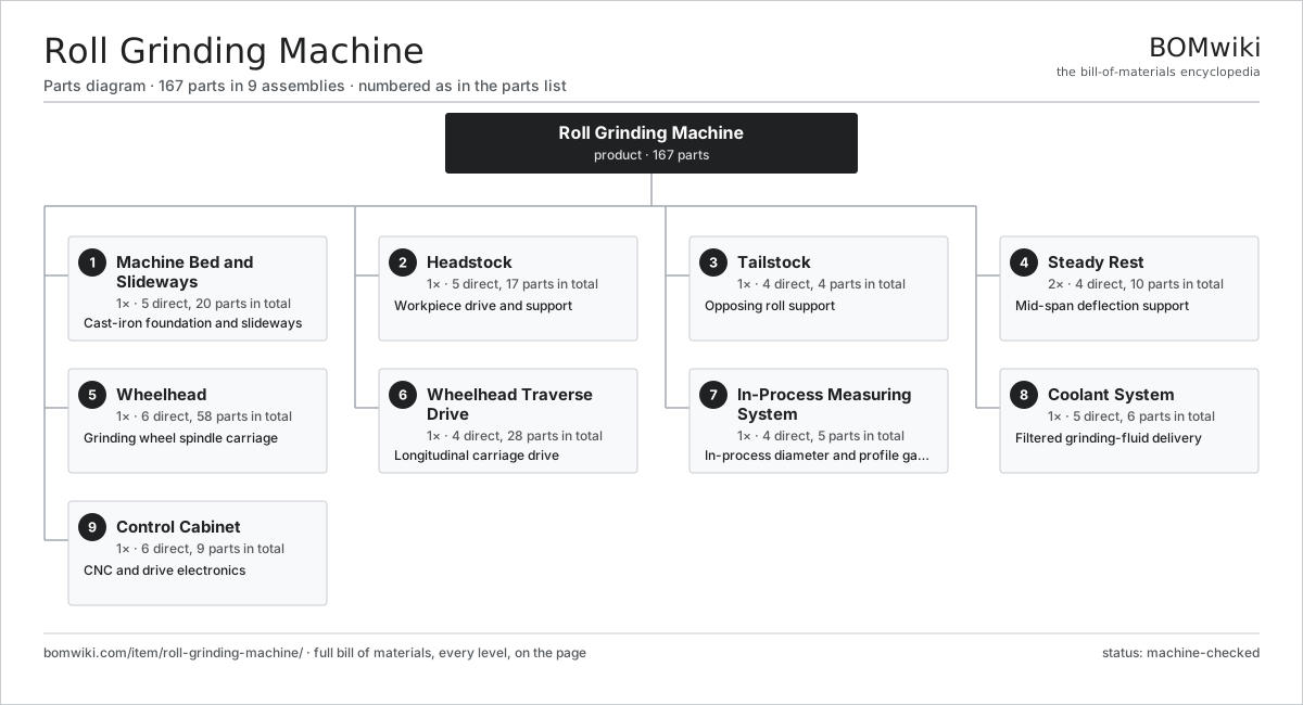
| # | Part | Qty | What it does |
|---|---|---|---|
| 1 | Machine Bed and Slideways 5 parts | 1× | Cast-iron foundation and slideways |
| 2 | Headstock 5 parts | 1× | Workpiece drive and support |
| 3 | Tailstock 4 parts | 1× | Opposing roll support |
| 4 | Steady Rest 4 parts | 2× | Mid-span deflection support |
| 5 | Wheelhead 6 parts | 1× | Grinding wheel spindle carriage |
| 6 | Wheelhead Traverse Drive 4 parts | 1× | Longitudinal carriage drive |
| 7 | In-Process Measuring System 4 parts | 1× | In-process diameter and profile gauging |
| 8 | Coolant System 5 parts | 1× | Filtered grinding-fluid delivery |
| 9 | Control Cabinet 6 parts | 1× | CNC and drive electronics |
3D model
No 3D model yet. Have a CAD file of this? Add a 3D model — STL renders right on this page; STEP, FreeCAD, and OpenSCAD sources are welcome too (openly licensed, like all 3D models on BOMwiki).
Build & assembly graph
expand / collapse · shared sub-assemblies converge · links to related products · est. labourTap an assembly to expand/collapse · tap a part to open it · use “Open page” for any node · drag to pan, scroll to zoom.
Bill of materials for Roll Grinding Machine
9 top-level lines · 67 rows shown · 167 parts total · indented to 3 levels| # | Item / sub-assembly | Part no. | Qty/assy | Ext. qty | Parts | Type |
|---|---|---|---|---|---|---|
| 1 | Machine Bed and Slideways 5 parts | rgm-machine-bed | 1× | 1 | 20 | assembly |
| 1.1 | Bed Casting | rgm-bed-casting | 1× | 1 | · | part |
| 1.2 | Vee Slideway | rgm-vee-slideway | 2× | 2 | · | part |
| 1.3 | Slideway Wiper Set | rgm-way-wiper-set | 4× | 4 | · | part |
| 1.4 | Leveling Mount | rgm-leveling-mount | 12× | 12 | · | part |
| 1.5 | Way Lubrication Pump | rgm-way-lube-pump | 1× | 1 | · | part |
| 2 | Headstock 5 parts | rgm-headstock | 1× | 1 | 17 | assembly |
| 2.1 | Headstock Spindle | rgm-headstock-spindle | 1× | 1 | · | part |
| 2.2 | Workpiece Drive Motor | rgm-headstock-drive-motor | 1× | 1 | · | part |
| 2.3 | Workpiece Gearbox 4 parts | rgm-gearbox | 1× | 1 | 10 | assembly |
| 2.3.1 | Helical Gear Pair | gear-pair | 2× | 2 | · | part |
| 2.3.2 | Gearbox Housing | gearbox-housing | 1× | 1 | · | part |
| 2.3.3 | Ball Bearing | ball-bearing | 4× | 4 | · | part |
| 2.3.4 | Oil Seal | oil-seal | 3× | 3 | · | part |
| 2.4 | Faceplate Drive Dog | rgm-faceplate-dog | 1× | 1 | · | part |
| 2.5 | Ball Bearing | ball-bearing | 4× | 4 | · | part |
| 3 | Tailstock 4 parts | rgm-tailstock | 1× | 1 | 4 | assembly |
| 3.1 | Tailstock Quill | rgm-tailstock-quill | 1× | 1 | · | part |
| 3.2 | Live Center | rgm-live-center | 1× | 1 | · | part |
| 3.3 | Tailstock Bed Clamp | rgm-tailstock-clamp | 1× | 1 | · | part |
| 3.4 | Tailstock Hydraulic Unit | rgm-tailstock-hydraulic | 1× | 1 | · | part |
| 4 | Steady Rest 4 parts | rgm-steady-rest-set | 2× | 2 | 10 | assembly |
| 4.1 | Steady Rest Shoe | rgm-steady-shoe | 3× | 6 | · | part |
| 4.2 | Steady Shoe Cylinder | rgm-steady-hydraulic-cyl | 3× | 6 | · | part |
| 4.3 | Steady Rest Base | rgm-steady-base | 1× | 2 | · | part |
| 4.4 | Pressure Sensor | pressure-sensor | 3× | 6 | · | part |
| 5 | Wheelhead 6 parts | rgm-wheelhead | 1× | 1 | 58 | assembly |
| 5.1 | Grinding Wheel Spindle | rgm-wheel-spindle | 1× | 1 | · | part |
| 5.2 | Grinding Wheel | rgm-grinding-wheel | 1× | 1 | · | part |
| 5.3 | Wheel Drive Motor | rgm-wheel-drive-motor | 1× | 1 | · | part |
| 5.4 | Infeed Slide 4 parts | rgm-infeed-slide | 1× | 1 | 28 | assembly |
| 5.4.1 | Ball Screw | ball-screw | 1× | 1 | · | part |
| 5.4.2 | Linear Guide Rail | linear-guide | 2× | 2 | · | part |
| 5.4.3 | Servo Motor 4 parts + deeper › | servo-motor | 1× | 1 | 24 | assembly |
| 5.4.4 | Infeed Linear Scale | rgm-linear-scale | 1× | 1 | · | part |
| 5.5 | Wheel Dresser Unit 3 parts | rgm-dresser-unit | 1× | 1 | 26 | assembly |
| 5.5.1 | Dressing Diamond | rgm-dresser-diamond | 1× | 1 | · | part |
| 5.5.2 | Dresser Slide | rgm-dresser-slide | 1× | 1 | · | part |
| 5.5.3 | Servo Motor 4 parts + deeper › | servo-motor | 1× | 1 | 24 | assembly |
| 5.6 | Wheel Guard | rgm-wheel-guard | 1× | 1 | · | part |
| 6 | Wheelhead Traverse Drive 4 parts | rgm-wheelhead-traverse | 1× | 1 | 28 | assembly |
| 6.1 | Ball Screw | ball-screw | 1× | 1 | · | part |
| 6.2 | Traverse Rack and Pinion | rgm-traverse-rack | 1× | 1 | · | part |
| 6.3 | Servo Motor 4 parts | servo-motor | 1× | 1 | 24 | assembly |
| 6.3.1 | Stator Assembly 3 parts + deeper › | stator-assembly | 1× | 1 | 3 | assembly |
| 6.3.2 | Rotor Assembly 4 parts + deeper › | rotor-assembly | 1× | 1 | 19 | assembly |
| 6.3.3 | Encoder | encoder | 1× | 1 | · | part |
| 6.3.4 | Motor Housing | motor-housing | 1× | 1 | · | part |
| 6.4 | Linear Guide Rail | linear-guide | 2× | 2 | · | part |
| 7 | In-Process Measuring System 4 parts | rgm-measuring-system | 1× | 1 | 5 | assembly |
| 7.1 | Diameter Caliper Gauge | rgm-diameter-caliper | 2× | 2 | · | part |
| 7.2 | Profile Probe | rgm-profile-probe | 1× | 1 | · | part |
| 7.3 | Roundness Pickup | rgm-roundness-pickup | 1× | 1 | · | part |
| 7.4 | Gauge Controller | rgm-gauge-controller | 1× | 1 | · | part |
| 8 | Coolant System 5 parts | rgm-coolant-system | 1× | 1 | 6 | assembly |
| 8.1 | Coolant Pump | rgm-coolant-pump | 2× | 2 | · | part |
| 8.2 | Coolant Tank | rgm-coolant-tank | 1× | 1 | · | part |
| 8.3 | Magnetic Separator | rgm-magnetic-separator | 1× | 1 | · | part |
| 8.4 | Paper-Band Filter | rgm-paper-filter | 1× | 1 | · | part |
| 8.5 | Coolant Chiller | rgm-coolant-chiller | 1× | 1 | · | part |
| 9 | Control Cabinet 6 parts | rgm-control-cabinet | 1× | 1 | 9 | assembly |
| 9.1 | CNC Controller | rgm-cnc-unit | 1× | 1 | · | part |
| 9.2 | Servo Drive | rgm-servo-drive | 4× | 4 | · | part |
| 9.3 | Power Supply | power-supply | 1× | 1 | · | part |
| 9.4 | Operator Panel | rgm-operator-panel | 1× | 1 | · | part |
| 9.5 | Vibration Monitor | rgm-vibration-monitor | 1× | 1 | · | part |
| 9.6 | Wire Bundle | wire-bundle | 1× | 1 | · | part |
Related products
same domain, ranked by shared parts Bevel Gear Generator
201 parts · shares 5 with this page
Centering and Facing Machine
1,419 parts · shares 5 with this page
Cold Rolling Mill
991 parts · shares 5 with this page
Bevel Gear Generator
201 parts · shares 5 with this page
Centering and Facing Machine
1,419 parts · shares 5 with this page
Cold Rolling Mill
991 parts · shares 5 with this page
 Creep-Feed Grinder
571 parts · shares 5 with this page
Cut-to-Length Line
500 parts · shares 5 with this page
Double-Disc Grinder
153 parts · shares 5 with this page
Creep-Feed Grinder
571 parts · shares 5 with this page
Cut-to-Length Line
500 parts · shares 5 with this page
Double-Disc Grinder
153 parts · shares 5 with this page
Sourcing: possible vendors
Prices, MOQ, and lead times are algorithmic estimates, not quotes, and not claims about these companies. Company mappings are curated by keyword; est. price band $10k–$1M. How estimates work| Vendor | HQ | Specialty | MOQ | Lead time |
|---|---|---|---|---|
|
🇩🇪DMG MORI
dmgmori.com ↗
|
Bielefeld, DE | Machine tools | 5 units | 12–20 wks |
|
🇯🇵Mazak
mazak.com ↗
|
Oguchi, JP | Machine tools | 5 units | 12–20 wks |
| haascnc.com ↗ | Oxnard, US | CNC machine tools | 5 units | 12–20 wks |
|
🇯🇵Okuma
okuma.com ↗
|
Niwa, JP | Machine tools | 5 units | 12–20 wks |
|
🇩🇪Trumpf
trumpf.com ↗
|
Ditzingen, DE | Laser & sheet-metal machines | 5 units | 12–20 wks |
971-word article