Plasma Arc Welding Machine
ProductOverview
A plasma arc welding machine joins metal with an arc that has been forced through a narrow water-cooled copper orifice, which squeezes it into a stiff collimated column far hotter and more directed than an open arc. The same tungsten electrode and inert gas used in TIG welding are present, but here a second gas stream and a constricting nozzle turn a soft, spreading arc into a focused jet that can reach roughly 20,000 K at its core. That concentration lets the process run from a fraction of an ampere for foil up to a few hundred amperes that punch a clean keyhole through several millimetres of plate in one pass. Because the arc column leaves the nozzle already shaped, the arc length matters far less than in TIG, so the weld stays steady as the torch height drifts.
The machine is built from several modules. The Plasma Torch holds the electrode and the constricting nozzle, the Inverter Power Source supplies the main transferred arc, and the Pilot Arc and HF Starter ionizes the gas and keeps a pilot arc alive between starts. The Gas Console meters the orifice gas separately from the shielding gas, the Cooling Unit removes heat from the torch, and the Cold Wire Feeder adds filler when the joint needs it. The Control Panel panel sets the current schedule and gas timing, and the Cart and Frame carries everything around the shop.
How the constricted arc works
The arc begins as a non-transferred pilot arc inside the torch, struck between the Tungsten Electrode and the Constricting Nozzle by the high-frequency spark from the Pilot Arc and HF Starter. This pilot ionizes the argon flowing through the Plasma Gas Diffuser so a conductive path already exists at the nozzle exit. When the operator calls for weld current, the main arc transfers from the electrode to the workpiece and the pilot can drop out. As the plasma gas passes the hot electrode it is heated, expands, and is forced through the small bore of the Constricting Nozzle, which is held to 0.8-3.2 mm. The constriction raises the current density and the gas velocity so the column leaves the orifice as a narrow, parallel-sided jet rather than the cone an open TIG arc makes. Around that jet the Shielding Cup lays down a separate curtain of shielding gas to keep air off the molten pool.
At low current the result is microplasma, a needle-fine arc that welds foil and fine wire without blowing it away. At higher current the jet works in melt-in mode like a stiff TIG arc, and at full current it drills a keyhole: the plasma bores a hole clean through the joint, and as the torch moves the molten metal flows around and closes behind it, giving a full-penetration weld with one pass and a flat, even underbead.
Power source and arc starting
The Inverter Power Source is a constant-current inverter. An Input Rectifier turns the mains into a DC bus smoothed by the Bus Capacitor banks, the IGBT Inverter Module chops that bus at tens of kilohertz with its Power IGBT switches, and the Power Transformer passes the power to the Output Rectifier that produces the welding DC. A Current Sensor feeds the output back so the regulator holds current steady regardless of arc length, which is the defining behaviour of a constant-current supply. The Pilot Arc and HF Starter adds two things the supply cannot do alone: the HF Spark Unit generates the high-voltage spark that ionizes the gas without touching the work, and the Pilot Arc Supply holds a few amperes of pilot current through the Pilot Ballast Resistor so the arc is always ready to transfer.
Gas, cooling, and filler
Plasma welding needs two gas streams, and the Gas Console keeps them separate. The Plasma Gas Controller meters the orifice gas, usually argon at 0.1-5 L/min, because that flow sets the stiffness and the heat of the jet. The Shield Gas Controller meters the shielding gas at 10-30 L/min, often argon with a few percent hydrogen to raise heat on stainless and nickel alloys. Both pass through the Gas Solenoid Valve valves and the Flow Meter gauges, fed from cylinders through the Gas Regulator stages with a Pressure Sensor watching each line.
Because the Constricting Nozzle sits right in the arc, it must be cooled hard or it will erode and lose its bore. The Cooling Unit unit circulates deionized water with the Circulation Pump, rejects the heat through the Coolant Radiator, and a Flow Switch inhibits the arc if flow is lost. When the joint needs added metal, the Cold Wire Feeder pushes cold filler with its Drive Roll pair and Wire Feed Motor into the front of the pool through the Wire Guide.
Variants and process modes
The same machine covers a wide range by how it is set. Microplasma machines run from 0.1 to about 15 A for foil, bellows, and instrument parts. Medium-current melt-in machines work like a more tolerant TIG setup for sheet and thin plate. Keyhole machines run 100 A and up to weld stainless, titanium, and nickel alloys from roughly 3 to 10 mm in a single pass. Some torches run on a robot or a lathe for tube and longitudinal seams, where the steady arc and the wide tolerance to torch height pay off. Most machines weld on DC straight polarity with the electrode negative; aluminium work uses variable-polarity supplies that switch the arc to clean the oxide film.
Use and limits
Plasma welding earns its place where a TIG arc is too soft or too sensitive to arc length: thin precision parts that microplasma can join without distortion, and thicker stainless or titanium that keyhole welding closes in one pass with a clean root. The constricted arc is stiffer than an open arc, so small changes in torch height barely change the weld, which suits automated and orbital work. The costs are real: the Plasma Torch is more complex than a TIG torch, the Constricting Nozzle is a wear part that must be set and replaced with care, and the Gas Console and Cooling Unit add plumbing a simple welder does not need. For low-volume hand work TIG is often cheaper and easier, but for fine parts and for clean single-pass full-penetration joints the plasma machine does what an open arc cannot.
Plasma Arc Welding Machine parts and their functions
8 top-level parts · 594 parts in total · full bill of materials below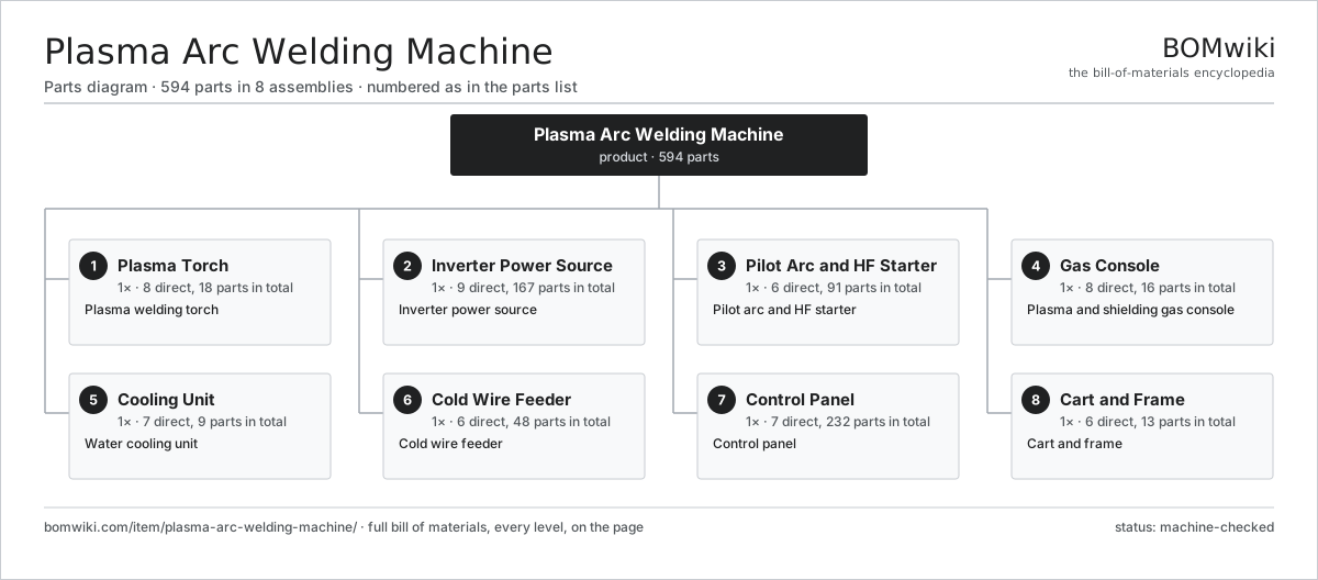
| # | Part | Qty | What it does |
|---|---|---|---|
| 1 | Plasma Torch 8 parts | 1× | Plasma welding torch |
| 2 | Inverter Power Source 9 parts | 1× | Inverter power source |
| 3 | Pilot Arc and HF Starter 6 parts | 1× | Pilot arc and HF starter |
| 4 | Gas Console 8 parts | 1× | Plasma and shielding gas console |
| 5 | Cooling Unit 7 parts | 1× | Water cooling unit |
| 6 | Cold Wire Feeder 6 parts | 1× | Cold wire feeder |
| 7 | Control Panel 7 parts | 1× | Control panel |
| 8 | Cart and Frame 6 parts | 1× | Cart and frame |
3D model
No 3D model yet. Have a CAD file of this? Add a 3D model — STL renders right on this page; STEP, FreeCAD, and OpenSCAD sources are welcome too (openly licensed, like all 3D models on BOMwiki).
Build & assembly graph
expand / collapse · shared sub-assemblies converge · links to related products · est. labourTap an assembly to expand/collapse · tap a part to open it · use “Open page” for any node · drag to pan, scroll to zoom.
Bill of materials for Plasma Arc Welding Machine
8 top-level lines · 95 rows shown · 594 parts total · indented to 3 levels| # | Item / sub-assembly | Part no. | Qty/assy | Ext. qty | Parts | Type |
|---|---|---|---|---|---|---|
| 1 | Plasma Torch 8 parts | plasma-arc-welding-machine-torch | 1× | 1 | 18 | assembly |
| 1.1 | Tungsten Electrode | plasma-arc-welding-machine-electrode | 1× | 1 | · | part |
| 1.2 | Electrode Collet | plasma-arc-welding-machine-collet | 1× | 1 | · | part |
| 1.3 | Constricting Nozzle | plasma-arc-welding-machine-nozzle | 1× | 1 | · | part |
| 1.4 | Shielding Cup | plasma-arc-welding-machine-shield-cup | 1× | 1 | · | part |
| 1.5 | Torch Body | plasma-arc-welding-machine-torch-body | 1× | 1 | · | part |
| 1.6 | Plasma Gas Diffuser | plasma-arc-welding-machine-gas-diffuser | 1× | 1 | · | part |
| 1.7 | Torch Cable 4 parts | plasma-arc-welding-machine-torch-cable | 1× | 1 | 9 | assembly |
| 1.7.1 | Power Conductor | plasma-arc-welding-machine-power-conductor | 1× | 1 | · | part |
| 1.7.2 | Coolant Hose | plasma-arc-welding-machine-coolant-hose | 2× | 2 | · | part |
| 1.7.3 | Gas Hose | plasma-arc-welding-machine-gas-hose | 2× | 2 | · | part |
| 1.7.4 | Connector | connector | 4× | 4 | · | part |
| 1.8 | O-Ring Set | oring-set | 3× | 3 | · | part |
| 2 | Inverter Power Source 9 parts | plasma-arc-welding-machine-power-source | 1× | 1 | 167 | assembly |
| 2.1 | Input Rectifier | plasma-arc-welding-machine-rectifier | 1× | 1 | · | part |
| 2.2 | IGBT Inverter Module 4 parts | plasma-arc-welding-machine-inverter-module | 1× | 1 | 154 | assembly |
| 2.2.1 | Power IGBT | plasma-arc-welding-machine-igbt | 6× | 6 | · | part |
| 2.2.2 | Gate Driver Board 3 parts + deeper › | plasma-arc-welding-machine-gate-driver | 1× | 1 | 67 | assembly |
| 2.2.3 | Bare PCB | pcb-bare | 1× | 1 | · | part |
| 2.2.4 | SMD Passive (R/C/L) | smd-passives | 80× | 80 | · | part |
| 2.3 | Power Transformer | plasma-arc-welding-machine-main-transformer | 1× | 1 | · | part |
| 2.4 | Output Rectifier | plasma-arc-welding-machine-output-rectifier | 1× | 1 | · | part |
| 2.5 | Bus Capacitor | plasma-arc-welding-machine-dc-bus-cap | 4× | 4 | · | part |
| 2.6 | Heat Sink | plasma-arc-welding-machine-heat-sink | 2× | 2 | · | part |
| 2.7 | Cooling Fan | plasma-arc-welding-machine-cooling-fan | 2× | 2 | · | part |
| 2.8 | Current Sensor | plasma-arc-welding-machine-current-sensor | 1× | 1 | · | part |
| 2.9 | Power Supply | power-supply | 1× | 1 | · | part |
| 3 | Pilot Arc and HF Starter 6 parts | plasma-arc-welding-machine-arc-starter | 1× | 1 | 91 | assembly |
| 3.1 | HF Spark Unit 4 parts | plasma-arc-welding-machine-hf-unit | 1× | 1 | 33 | assembly |
| 3.1.1 | Spark Gap | plasma-arc-welding-machine-spark-gap | 1× | 1 | · | part |
| 3.1.2 | HF Coupling Transformer | plasma-arc-welding-machine-hf-coupling | 1× | 1 | · | part |
| 3.1.3 | Bare PCB | pcb-bare | 1× | 1 | · | part |
| 3.1.4 | SMD Passive (R/C/L) | smd-passives | 30× | 30 | · | part |
| 3.2 | Pilot Arc Supply 4 parts | plasma-arc-welding-machine-pilot-supply | 1× | 1 | 53 | assembly |
| 3.2.1 | Bare PCB | pcb-bare | 1× | 1 | · | part |
| 3.2.2 | Microcontroller | mcu | 1× | 1 | · | part |
| 3.2.3 | Relay | relay | 1× | 1 | · | part |
| 3.2.4 | SMD Passive (R/C/L) | smd-passives | 50× | 50 | · | part |
| 3.3 | Pilot Ballast Resistor | plasma-arc-welding-machine-pilot-resistor | 1× | 1 | · | part |
| 3.4 | HF Coupling Transformer | plasma-arc-welding-machine-hf-coupling | 1× | 1 | · | part |
| 3.5 | Spark Gap | plasma-arc-welding-machine-spark-gap | 1× | 1 | · | part |
| 3.6 | Relay | relay | 2× | 2 | · | part |
| 4 | Gas Console 8 parts | plasma-arc-welding-machine-gas-console | 1× | 1 | 16 | assembly |
| 4.1 | Plasma Gas Controller | plasma-arc-welding-machine-plasma-gas-mfc | 1× | 1 | · | part |
| 4.2 | Shield Gas Controller | plasma-arc-welding-machine-shield-gas-mfc | 1× | 1 | · | part |
| 4.3 | Gas Solenoid Valve | plasma-arc-welding-machine-gas-solenoid | 3× | 3 | · | part |
| 4.4 | Flow Meter | plasma-arc-welding-machine-flowmeter | 2× | 2 | · | part |
| 4.5 | Gas Regulator | plasma-arc-welding-machine-gas-regulator | 2× | 2 | · | part |
| 4.6 | Gas Manifold | plasma-arc-welding-machine-gas-manifold | 1× | 1 | · | part |
| 4.7 | Pressure Sensor | pressure-sensor | 2× | 2 | · | part |
| 4.8 | O-Ring Set | oring-set | 4× | 4 | · | part |
| 5 | Cooling Unit 7 parts | plasma-arc-welding-machine-cooling | 1× | 1 | 9 | assembly |
| 5.1 | Coolant Radiator | plasma-arc-welding-machine-radiator | 1× | 1 | · | part |
| 5.2 | Circulation Pump | plasma-arc-welding-machine-coolant-pump | 1× | 1 | · | part |
| 5.3 | Reservoir Tank | plasma-arc-welding-machine-coolant-tank | 1× | 1 | · | part |
| 5.4 | Radiator Fan | plasma-arc-welding-machine-fan-radiator | 1× | 1 | · | part |
| 5.5 | Flow Switch | plasma-arc-welding-machine-flow-switch | 1× | 1 | · | part |
| 5.6 | Coolant Hose | plasma-arc-welding-machine-coolant-hose | 2× | 2 | · | part |
| 5.7 | O-Ring Set | oring-set | 2× | 2 | · | part |
| 6 | Cold Wire Feeder 6 parts | plasma-arc-welding-machine-wire-feeder | 1× | 1 | 48 | assembly |
| 6.1 | Wire Feed Motor | plasma-arc-welding-machine-feed-motor | 1× | 1 | · | part |
| 6.2 | Drive Roll | plasma-arc-welding-machine-drive-roll | 2× | 2 | · | part |
| 6.3 | Wire Guide | plasma-arc-welding-machine-wire-guide | 1× | 1 | · | part |
| 6.4 | Spool Holder | plasma-arc-welding-machine-spool-holder | 1× | 1 | · | part |
| 6.5 | Feeder Board 3 parts | plasma-arc-welding-machine-feeder-board | 1× | 1 | 42 | assembly |
| 6.5.1 | Bare PCB | pcb-bare | 1× | 1 | · | part |
| 6.5.2 | Microcontroller | mcu | 1× | 1 | · | part |
| 6.5.3 | SMD Passive (R/C/L) | smd-passives | 40× | 40 | · | part |
| 6.6 | Helical Gear Pair | gear-pair | 1× | 1 | · | part |
| 7 | Control Panel 7 parts | plasma-arc-welding-machine-control | 1× | 1 | 232 | assembly |
| 7.1 | Main Control Board 5 parts | plasma-arc-welding-machine-control-board | 1× | 1 | 176 | assembly |
| 7.1.1 | Bare PCB | pcb-bare | 1× | 1 | · | part |
| 7.1.2 | Microcontroller | mcu | 2× | 2 | · | part |
| 7.1.3 | Power Supply | power-supply | 1× | 1 | · | part |
| 7.1.4 | SMD Passive (R/C/L) | smd-passives | 160× | 160 | · | part |
| 7.1.5 | Connector | connector | 12× | 12 | · | part |
| 7.2 | Operator Display 3 parts | plasma-arc-welding-machine-display | 1× | 1 | 3 | assembly |
| 7.2.1 | LCD Panel | lcd-panel | 1× | 1 | · | part |
| 7.2.2 | Bare PCB | pcb-bare | 1× | 1 | · | part |
| 7.2.3 | Microcontroller | mcu | 1× | 1 | · | part |
| 7.3 | Front Panel | plasma-arc-welding-machine-front-panel | 1× | 1 | · | part |
| 7.4 | Foot Pedal | plasma-arc-welding-machine-foot-pedal | 1× | 1 | · | part |
| 7.5 | I/O Board 3 parts | plasma-arc-welding-machine-io-board | 1× | 1 | 25 | assembly |
| 7.5.1 | Bare PCB | pcb-bare | 1× | 1 | · | part |
| 7.5.2 | Relay | relay | 8× | 8 | · | part |
| 7.5.3 | Connector | connector | 16× | 16 | · | part |
| 7.6 | Wire Bundle | wire-bundle | 2× | 2 | · | part |
| 7.7 | Connector | connector | 24× | 24 | · | part |
| 8 | Cart and Frame 6 parts | plasma-arc-welding-machine-cart | 1× | 1 | 13 | assembly |
| 8.1 | Steel Frame | plasma-arc-welding-machine-frame | 1× | 1 | · | part |
| 8.2 | Caster | plasma-arc-welding-machine-caster | 4× | 4 | · | part |
| 8.3 | Cylinder Bracket | plasma-arc-welding-machine-cylinder-bracket | 1× | 1 | · | part |
| 8.4 | Enclosure Panel | plasma-arc-welding-machine-enclosure-panel | 4× | 4 | · | part |
| 8.5 | Sheet Metal Panel | sheet-panel | 2× | 2 | · | part |
| 8.6 | Fastener Set | fastener-set | 1× | 1 | · | part |
Related products
same domain, ranked by shared parts Angle Roll Bender
100 parts · shares 4 with this page
Bar Chamfering Machine
1,148 parts · shares 4 with this page
Centering and Facing Machine
1,419 parts · shares 4 with this page
CNC Metal Spinning Machine
768 parts · shares 4 with this page
Angle Roll Bender
100 parts · shares 4 with this page
Bar Chamfering Machine
1,148 parts · shares 4 with this page
Centering and Facing Machine
1,419 parts · shares 4 with this page
CNC Metal Spinning Machine
768 parts · shares 4 with this page
 Continuous Belt Furnace
130 parts · shares 4 with this page
Continuous Belt Furnace
130 parts · shares 4 with this page
 Crankshaft Grinder
511 parts · shares 4 with this page
Crankshaft Grinder
511 parts · shares 4 with this page
Sourcing: possible vendors
Prices, MOQ, and lead times are algorithmic estimates, not quotes, and not claims about these companies. Company mappings are curated by keyword; est. price band $10k–$1M. How estimates work| Vendor | HQ | Specialty | MOQ | Lead time |
|---|---|---|---|---|
|
🇩🇪DMG MORI
dmgmori.com ↗
|
Bielefeld, DE | Machine tools | 5 units | 12–20 wks |
|
🇯🇵Mazak
mazak.com ↗
|
Oguchi, JP | Machine tools | 5 units | 12–20 wks |
| haascnc.com ↗ | Oxnard, US | CNC machine tools | 5 units | 12–20 wks |
|
🇯🇵Okuma
okuma.com ↗
|
Niwa, JP | Machine tools | 5 units | 12–20 wks |
|
🇩🇪Trumpf
trumpf.com ↗
|
Ditzingen, DE | Laser & sheet-metal machines | 5 units | 12–20 wks |
1,231-word article