Universal Cylindrical Grinder
ProductOverview
A universal cylindrical grinder finishes round parts to close size, roundness, and surface finish by spinning the work slowly against a fast abrasive wheel. The word universal means two parts of the machine swivel: the Grinding Wheelhead that carries the external wheel and the Swiveling Workhead that turns the part. Because both can be set at an angle, one machine grinds outside diameters, inside diameters, shoulders and faces, and tapers of almost any angle. A plain cylindrical grinder does external diameters only; the universal version adds the Internal Grinding Attachment and the two swivels, which is why it is the standard machine in toolrooms and short-run shops that cannot justify a separate grinder for every feature. Production lines that grind the same part all day usually use simpler dedicated machines, but for varied work the universal grinder does the most on one setup. Roundness of 0.3-1 micron and size held to a couple of microns are routine.
How it grinds
The part is held two ways. For shafts it runs between a center in the workhead and a center in the Tailstock, driven by a Drive Plate and Dog clamped to one end. Grinding between dead centers is the most accurate way to hold round work, because the part turns on the same two reference points every pass and the workhead spindle bearings never enter the error chain. For parts with no center holes, such as flanged or hollow pieces, the Work Chuck grips the work and the workhead spindle drives it directly.
While the part rotates slowly, the Lower Table reciprocates it back and forth along its axis so the wheel sweeps the whole length, and the Cross-Slide feeds the wheel in for size. Two infeed strategies cover most work. In traverse grinding the wheel takes a small diametral cut and the table strokes the part past it repeatedly, good for long surfaces and fine finishes. In plunge grinding the table holds still and the wheel feeds straight in across a surface narrower than the wheel, which is faster for short journals and ground forms. The Table Trip Dogs set where the table reverses, and dwell at each reversal evens out the stroke ends.
Grinding tapers
Tapers are where the universal layout earns its name, and there are three ways to make one. Long shallow tapers are ground by swiveling the Upper Swivel Table a few degrees, so the part axis sits at a slight angle to the table travel and the wheel cuts progressively deeper along the length. Short steep tapers are ground by swiveling the Swiveling Workhead instead, angling the whole part to the wheel, since a table swivel cannot reach steep angles within its travel. Very steep tapers and shoulder faces are ground by swiveling the Grinding Wheelhead so the wheel face presents at the needed angle. Choosing among the three depends on taper angle and length, and a good setup leaves the taper straight and on-gauge without blending marks where passes meet.
Internal and face work
The Internal Grinding Attachment swings a high-speed spindle into line with the bore. Because an internal wheel is small, it must spin very fast, 15,000 to 60,000 rpm, for the abrasive to reach a useful surface speed inside the hole. The Internal Wheel on its quill grinds straight bores and internal tapers, and grinding the OD and ID on one setup keeps them concentric to each other far better than moving the part to a second machine. Faces and shoulders are ground with the side of the external wheel, often with the Wheelhead Swivel Base set so the wheel face runs true to the shoulder.
Holding accuracy
Cylindrical grinding removes little metal but is very sensitive to vibration, heat, and deflection. The Bed Casting is grey iron or polymer concrete at 1.5-6 t for its damping, and the Wheel Spindle runs in hydrodynamic or precision angular-contact bearings whose stiffness bounds the roundness the machine can hold. The Wheel Balancer cancels wheel unbalance, since a few grams print chatter waves onto the finish. Slender shafts bow away from wheel pressure, so a Steady Rest backs the work up along its length. The Center Preload Spring keeps a steady light force on the centers as the part heats and lengthens, so it stays seated without being crushed. Heat is the main size error: the Coolant System system floods the contact through Coolant Nozzles, the Filter Unit strips swarf and grit that would scratch the surface, and a Coolant Chiller holds coolant within about half a degree.
Dressing and control
The wheel is consumable and is trued with diamond. The Diamond Dresser draws a Dressing Diamond across the wheel to renew sharp grain and set the profile, and dressing feed sets the finish the wheel leaves. Every dress removes wheel radius, so the CNC Control compensates the cross-slide position automatically and re-feeds the lost material. On manual toolroom machines the operator does this by handwheel using the Infeed Screw. Production setups close the loop with a In-Process Gauge riding the work, stopping the infeed exactly at finished diameter no matter how worn the wheel is. Between manual toolroom grinders and full CNC machines, the universal cylindrical grinder spans a wide range of automation, but the geometry of holding the part round and feeding the wheel to size stays the same across all of them.
Universal Cylindrical Grinder parts and their functions
9 top-level parts · 153 parts in total · full bill of materials below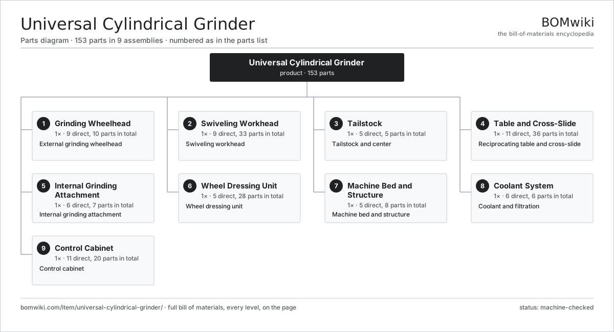
| # | Part | Qty | What it does |
|---|---|---|---|
| 1 | Grinding Wheelhead 9 parts | 1× | External grinding wheelhead |
| 2 | Swiveling Workhead 9 parts | 1× | Swiveling workhead |
| 3 | Tailstock 5 parts | 1× | Tailstock and center |
| 4 | Table and Cross-Slide 11 parts | 1× | Reciprocating table and cross-slide |
| 5 | Internal Grinding Attachment 6 parts | 1× | Internal grinding attachment |
| 6 | Wheel Dressing Unit 5 parts | 1× | Wheel dressing unit |
| 7 | Machine Bed and Structure 5 parts | 1× | Machine bed and structure |
| 8 | Coolant System 6 parts | 1× | Coolant and filtration |
| 9 | Control Cabinet 11 parts | 1× | Control cabinet |
3D model
No 3D model yet. Have a CAD file of this? Add a 3D model — STL renders right on this page; STEP, FreeCAD, and OpenSCAD sources are welcome too (openly licensed, like all 3D models on BOMwiki).
Build & assembly graph
expand / collapse · shared sub-assemblies converge · links to related products · est. labourTap an assembly to expand/collapse · tap a part to open it · use “Open page” for any node · drag to pan, scroll to zoom.
Bill of materials for Universal Cylindrical Grinder
9 top-level lines · 88 rows shown · 153 parts total · indented to 3 levels| # | Item / sub-assembly | Part no. | Qty/assy | Ext. qty | Parts | Type |
|---|---|---|---|---|---|---|
| 1 | Grinding Wheelhead 9 parts | universal-cylindrical-grinder-wheelhead | 1× | 1 | 10 | assembly |
| 1.1 | Grinding Wheel | universal-cylindrical-grinder-grinding-wheel | 1× | 1 | · | part |
| 1.2 | Wheel Spindle | universal-cylindrical-grinder-wheel-spindle | 1× | 1 | · | part |
| 1.3 | Wheelhead Motor | universal-cylindrical-grinder-wheelhead-motor | 1× | 1 | · | part |
| 1.4 | Wheel Flanges | universal-cylindrical-grinder-wheel-flanges | 1× | 1 | · | part |
| 1.5 | Wheel Guard | universal-cylindrical-grinder-wheel-guard | 1× | 1 | · | part |
| 1.6 | Wheel Balancer | universal-cylindrical-grinder-wheel-balancer | 1× | 1 | · | part |
| 1.7 | Wheelhead Swivel Base | universal-cylindrical-grinder-wheelhead-swivel | 1× | 1 | · | part |
| 1.8 | Drive Belt | drive-belt | 1× | 1 | · | part |
| 1.9 | Ball Bearing | ball-bearing | 2× | 2 | · | part |
| 2 | Swiveling Workhead 9 parts | universal-cylindrical-grinder-workhead | 1× | 1 | 33 | assembly |
| 2.1 | Workhead Spindle | universal-cylindrical-grinder-workhead-spindle | 1× | 1 | · | part |
| 2.2 | Work Center | universal-cylindrical-grinder-workhead-center | 1× | 1 | · | part |
| 2.3 | Drive Plate and Dog | universal-cylindrical-grinder-drive-dog | 1× | 1 | · | part |
| 2.4 | Work Chuck | universal-cylindrical-grinder-chuck | 1× | 1 | · | part |
| 2.5 | Workhead Swivel Base | universal-cylindrical-grinder-workhead-swivel | 1× | 1 | · | part |
| 2.6 | Servo Motor 4 parts | servo-motor | 1× | 1 | 24 | assembly |
| 2.6.1 | Stator Assembly 3 parts + deeper › | stator-assembly | 1× | 1 | 3 | assembly |
| 2.6.2 | Rotor Assembly 4 parts + deeper › | rotor-assembly | 1× | 1 | 19 | assembly |
| 2.6.3 | Encoder | encoder | 1× | 1 | · | part |
| 2.6.4 | Motor Housing | motor-housing | 1× | 1 | · | part |
| 2.7 | Gearbox Housing | gearbox-housing | 1× | 1 | · | part |
| 2.8 | Encoder | encoder | 1× | 1 | · | part |
| 2.9 | Ball Bearing | ball-bearing | 2× | 2 | · | part |
| 3 | Tailstock 5 parts | universal-cylindrical-grinder-tailstock | 1× | 1 | 5 | assembly |
| 3.1 | Tailstock Body | universal-cylindrical-grinder-tailstock-body | 1× | 1 | · | part |
| 3.2 | Tailstock Quill | universal-cylindrical-grinder-tailstock-quill | 1× | 1 | · | part |
| 3.3 | Center Preload Spring | universal-cylindrical-grinder-tailstock-spring | 1× | 1 | · | part |
| 3.4 | Tailstock Clamp | universal-cylindrical-grinder-tailstock-clamp | 1× | 1 | · | part |
| 3.5 | Coil Spring | coil-spring | 1× | 1 | · | part |
| 4 | Table and Cross-Slide 11 parts | universal-cylindrical-grinder-table | 1× | 1 | 36 | assembly |
| 4.1 | Lower Table | universal-cylindrical-grinder-lower-table | 1× | 1 | · | part |
| 4.2 | Upper Swivel Table | universal-cylindrical-grinder-upper-table | 1× | 1 | · | part |
| 4.3 | Cross-Slide | universal-cylindrical-grinder-cross-slide | 1× | 1 | · | part |
| 4.4 | Table Drive | universal-cylindrical-grinder-table-drive | 1× | 1 | · | part |
| 4.5 | Infeed Screw | universal-cylindrical-grinder-infeed-screw | 1× | 1 | · | part |
| 4.6 | Table Trip Dogs | universal-cylindrical-grinder-table-trips | 2× | 2 | · | part |
| 4.7 | In-Process Gauge | universal-cylindrical-grinder-size-gauge | 1× | 1 | · | part |
| 4.8 | Linear Guide Rail | linear-guide | 2× | 2 | · | part |
| 4.9 | Ball Screw | ball-screw | 1× | 1 | · | part |
| 4.10 | Servo Motor 4 parts | servo-motor | 1× | 1 | 24 | assembly |
| 4.10.1 | Stator Assembly 3 parts + deeper › | stator-assembly | 1× | 1 | 3 | assembly |
| 4.10.2 | Rotor Assembly 4 parts + deeper › | rotor-assembly | 1× | 1 | 19 | assembly |
| 4.10.3 | Encoder | encoder | 1× | 1 | · | part |
| 4.10.4 | Motor Housing | motor-housing | 1× | 1 | · | part |
| 4.11 | Encoder | encoder | 1× | 1 | · | part |
| 5 | Internal Grinding Attachment 6 parts | universal-cylindrical-grinder-internal-attach | 1× | 1 | 7 | assembly |
| 5.1 | Internal Spindle | universal-cylindrical-grinder-id-spindle | 1× | 1 | · | part |
| 5.2 | Internal Wheel | universal-cylindrical-grinder-id-wheel | 1× | 1 | · | part |
| 5.3 | Swing-Down Mount | universal-cylindrical-grinder-id-swing | 1× | 1 | · | part |
| 5.4 | ID Spindle Motor | universal-cylindrical-grinder-id-motor | 1× | 1 | · | part |
| 5.5 | Ball Bearing | ball-bearing | 2× | 2 | · | part |
| 5.6 | Drive Belt | drive-belt | 1× | 1 | · | part |
| 6 | Wheel Dressing Unit 5 parts | universal-cylindrical-grinder-dressing | 1× | 1 | 28 | assembly |
| 6.1 | Diamond Dresser | universal-cylindrical-grinder-dresser | 1× | 1 | · | part |
| 6.2 | Dressing Diamond | universal-cylindrical-grinder-diamond | 1× | 1 | · | part |
| 6.3 | Dresser Slide | universal-cylindrical-grinder-dress-slide | 1× | 1 | · | part |
| 6.4 | Ball Screw | ball-screw | 1× | 1 | · | part |
| 6.5 | Servo Motor 4 parts | servo-motor | 1× | 1 | 24 | assembly |
| 6.5.1 | Stator Assembly 3 parts + deeper › | stator-assembly | 1× | 1 | 3 | assembly |
| 6.5.2 | Rotor Assembly 4 parts + deeper › | rotor-assembly | 1× | 1 | 19 | assembly |
| 6.5.3 | Encoder | encoder | 1× | 1 | · | part |
| 6.5.4 | Motor Housing | motor-housing | 1× | 1 | · | part |
| 7 | Machine Bed and Structure 5 parts | universal-cylindrical-grinder-bed | 1× | 1 | 8 | assembly |
| 7.1 | Bed Casting | universal-cylindrical-grinder-bed-casting | 1× | 1 | · | part |
| 7.2 | Leveling Mount | universal-cylindrical-grinder-leveling | 4× | 4 | · | part |
| 7.3 | Machine Enclosure | universal-cylindrical-grinder-enclosure | 1× | 1 | · | part |
| 7.4 | Steady Rest | universal-cylindrical-grinder-steady-rest | 1× | 1 | · | part |
| 7.5 | Fastener Set | fastener-set | 1× | 1 | · | part |
| 8 | Coolant System 6 parts | universal-cylindrical-grinder-coolant | 1× | 1 | 6 | assembly |
| 8.1 | Coolant Pump | coolant-pump | 1× | 1 | · | part |
| 8.2 | Coolant Tank | universal-cylindrical-grinder-coolant-tank | 1× | 1 | · | part |
| 8.3 | Filter Unit | universal-cylindrical-grinder-filter-unit | 1× | 1 | · | part |
| 8.4 | Coolant Nozzles | universal-cylindrical-grinder-coolant-nozzles | 1× | 1 | · | part |
| 8.5 | Coolant Chiller | universal-cylindrical-grinder-chiller | 1× | 1 | · | part |
| 8.6 | Pressure Sensor | pressure-sensor | 1× | 1 | · | part |
| 9 | Control Cabinet 11 parts | universal-cylindrical-grinder-controls | 1× | 1 | 20 | assembly |
| 9.1 | CNC Control | universal-cylindrical-grinder-cnc | 1× | 1 | · | part |
| 9.2 | Operator HMI | universal-cylindrical-grinder-hmi | 1× | 1 | · | part |
| 9.3 | Power Supply | power-supply | 1× | 1 | · | part |
| 9.4 | IGBT Power Module | igbt-module | 2× | 2 | · | part |
| 9.5 | Bare PCB | pcb-bare | 1× | 1 | · | part |
| 9.6 | Microcontroller | mcu | 1× | 1 | · | part |
| 9.7 | SMD Passive (R/C/L) | smd-passives | 1× | 1 | · | part |
| 9.8 | Relay | relay | 4× | 4 | · | part |
| 9.9 | Connector | connector | 6× | 6 | · | part |
| 9.10 | Wire Bundle | wire-bundle | 1× | 1 | · | part |
| 9.11 | LCD Panel | lcd-panel | 1× | 1 | · | part |
Related products
same domain, ranked by shared parts Bevel Gear Generator
201 parts · shares 9 with this page
Bevel Gear Generator
201 parts · shares 9 with this page
 Rotary-Table Surface Grinder
172 parts · shares 9 with this page
Spline Rolling Machine
138 parts · shares 8 with this page
Rotary-Table Surface Grinder
172 parts · shares 9 with this page
Spline Rolling Machine
138 parts · shares 8 with this page
 Radial Forging Machine
288 parts · shares 8 with this page
Double-Disc Grinder
153 parts · shares 8 with this page
Radial Forging Machine
288 parts · shares 8 with this page
Double-Disc Grinder
153 parts · shares 8 with this page
 Gear Shaping Machine
110 parts · shares 7 with this page
Gear Shaping Machine
110 parts · shares 7 with this page
Sourcing: possible vendors
Prices, MOQ, and lead times are algorithmic estimates, not quotes, and not claims about these companies. Company mappings are curated by keyword; est. price band $10k–$1M. How estimates work| Vendor | HQ | Specialty | MOQ | Lead time |
|---|---|---|---|---|
|
🇩🇪DMG MORI
dmgmori.com ↗
|
Bielefeld, DE | Machine tools | 5 units | 12–20 wks |
|
🇯🇵Mazak
mazak.com ↗
|
Oguchi, JP | Machine tools | 5 units | 12–20 wks |
| haascnc.com ↗ | Oxnard, US | CNC machine tools | 5 units | 12–20 wks |
|
🇯🇵Okuma
okuma.com ↗
|
Niwa, JP | Machine tools | 5 units | 12–20 wks |
|
🇩🇪Trumpf
trumpf.com ↗
|
Ditzingen, DE | Laser & sheet-metal machines | 5 units | 12–20 wks |
975-word article