Camshaft Grinder
ProductOverview
A camshaft grinder finishes the working surfaces of an engine camshaft after forging or casting, hardening, and rough machining. A camshaft has two kinds of surface to grind: the bearing journals, which are simple cylinders that locate the shaft in the head or block, and the cam lobes, which are non-circular profiles that open and close the valves. The lobe shape sets valve timing and lift, so it must be ground to a defined profile within a few microns at every angle around the cam. This machine grinds both on one setup. The lobes are generated by feeding the wheelhead in and out once per cam revolution in step with the cam angle, using the Wheelhead & Spindle, the C-axis C-Axis Headstock, and the CNC X-C Interpolation Control that ties them together.
Everything mounts on the Base & Ways, a mineral-cast base chosen for damping because lobe grinding is an interrupted, varying-load cut that invites chatter. The cam is held between the headstock and the Tailstock, supported by a Steady Rest rest, and measured during the cut by the In-Process Gauge.
How it works
The cam is mounted between centers. Its drive end is gripped by the Work Faceplate through a Driving Dog, and a Angular Index Pin sets it to a known angle so all lobe timing is referenced to one datum. The free end runs on the Live Center in the tailstock, which advances its Tailstock Quill hydraulically to clamp the shaft at a set force.
Journals are ground first or last as plain cylinders: the cam turns slowly on the C axis and the X Infeed Slide feeds the wheel straight in until the In-Process Gauge reports final diameter. Lobes are the reason the machine is CNC. As the cam turns, the wheelhead must move in toward the cam over the lobe nose and back out over the base circle, completing one full rise-and-fall for every cam revolution. The C-Axis Encoder reports cam angle continuously and the CNC X-C Interpolation Control interpolates X infeed against that angle, so the path of the wheel center traces the cam profile. Because the wheel has a finite radius, the control compensates for wheel diameter as it dresses down, otherwise the ground lobe would not match the intended profile.
On older machines this motion came from a hardened master cam: a copy of the lobe turned with the work and a follower pushed the wheelhead, so the master shape was copied onto the part. A separate master was needed for every lobe profile. The CNC X-C method described here replaces the master with stored profile data, so a new lobe is a new program rather than a new piece of tooling, and the same machine grinds a wide mix of cams.
Wheelhead and spindle
The Wheel Spindle Cartridge carries the wheel arbor on angular-contact Ball Bearing sets sealed by Oil Seal elements and driven by the Wheel Spindle Motor through a Drive Belt. The CBN Grinding Wheel is narrow so it can reach between adjacent lobes, and it is electroplated CBN because the lobes are through-hardened and CBN holds its form far longer than a vitrified wheel. The X Infeed Slide is the most demanding axis on the machine: it must accelerate the whole wheelhead in and out once per revolution and still hold position to a fraction of a micron, so it uses a stiff Ball Screw on Linear Guide Rail rails driven by a high-response Servo Motor with a X-Axis Glass Scale for closed-loop feedback. A Auto Wheel Balancer trims wheel unbalance at speed, since any unbalance would print onto the lobe profile.
Workholding and support
A camshaft is long and thin, so it bends under wheel pressure if unsupported. The Steady Rest rest closes a Support Shoe onto a finished journal to hold the shaft against the wheel during lobe grinding. The tailstock keeps the cam loaded between centers at a controlled force so it neither springs nor digs into the centers. Because both the steady shoes and the live center ride finished surfaces, the High-Pressure Coolant System must keep those contacts clean of swarf.
Wheel dressing
A CBN lobe wheel must stay round and keep its edge form, because its profile is folded into the lobe shape through the control. The CBN Wheel Dresser feeds a powered Rotary Diamond Disc across the wheel on its own slide, and after each dress the control updates the wheel diameter it uses in the profile calculation. Dressing is light and scheduled by part count, since CBN wears slowly.
Coolant, control and variants
The High-Pressure Coolant System system floods the grind zone through Coherent-Jet Nozzle jets and recirculates filtered fluid, while a Coolant Chiller holds coolant temperature so the base and cam do not grow during a shift. The CNC X-C Interpolation Control coordinates the X infeed servo, the C-axis drive, the gauge, and the dresser, with the X-C interpolation as its core task. Machines of this type range from single-wheel shop grinders that regrind worn or reprofiled cams to multi-station production grinders in engine plants that grind several lobes at once. The base, headstock, wheelhead, gauge, and dresser are common across the range; production machines add wheels and automated loading, while a shop machine keeps one wheel and leans on the In-Process Gauge and stored profiles to cover many different cam designs.
Camshaft Grinder parts and their functions
11 top-level parts · 489 parts in total · full bill of materials below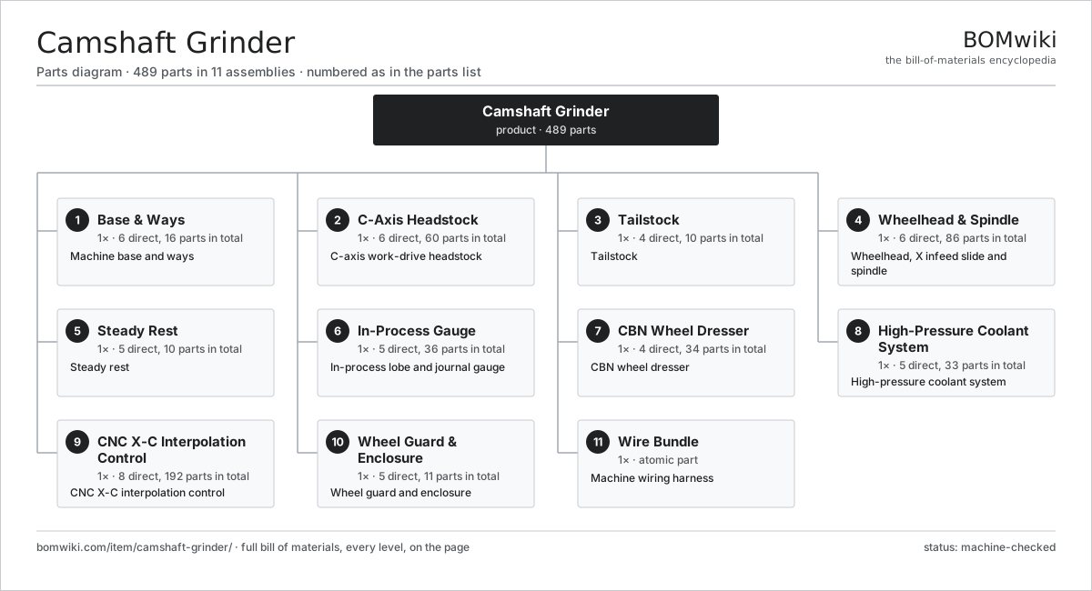
| # | Part | Qty | What it does |
|---|---|---|---|
| 1 | Base & Ways 6 parts | 1× | Machine base and ways |
| 2 | C-Axis Headstock 6 parts | 1× | C-axis work-drive headstock |
| 3 | Tailstock 4 parts | 1× | Tailstock |
| 4 | Wheelhead & Spindle 6 parts | 1× | Wheelhead, X infeed slide and spindle |
| 5 | Steady Rest 5 parts | 1× | Steady rest |
| 6 | In-Process Gauge 5 parts | 1× | In-process lobe and journal gauge |
| 7 | CBN Wheel Dresser 4 parts | 1× | CBN wheel dresser |
| 8 | High-Pressure Coolant System 5 parts | 1× | High-pressure coolant system |
| 9 | CNC X-C Interpolation Control 8 parts | 1× | CNC X-C interpolation control |
| 10 | Wheel Guard & Enclosure 5 parts | 1× | Wheel guard and enclosure |
| 11 | Wire Bundle | 1× | Machine wiring harness |
3D model
No 3D model yet. Have a CAD file of this? Add a 3D model — STL renders right on this page; STEP, FreeCAD, and OpenSCAD sources are welcome too (openly licensed, like all 3D models on BOMwiki).
Build & assembly graph
expand / collapse · shared sub-assemblies converge · links to related products · est. labourTap an assembly to expand/collapse · tap a part to open it · use “Open page” for any node · drag to pan, scroll to zoom.
Bill of materials for Camshaft Grinder
11 top-level lines · 140 rows shown · 489 parts total · indented to 3 levels| # | Item / sub-assembly | Part no. | Qty/assy | Ext. qty | Parts | Type |
|---|---|---|---|---|---|---|
| 1 | Base & Ways 6 parts | camshaft-grinder-base | 1× | 1 | 16 | assembly |
| 1.1 | Base Casting | camshaft-grinder-base-casting | 1× | 1 | · | part |
| 1.2 | Longitudinal (Z) Way | camshaft-grinder-z-way | 2× | 2 | · | part |
| 1.3 | Wheelhead (X) Way | camshaft-grinder-x-way | 2× | 2 | · | part |
| 1.4 | Telescopic Way Cover | camshaft-grinder-way-cover | 4× | 4 | · | part |
| 1.5 | Leveling Foot | camshaft-grinder-leveling-foot | 6× | 6 | · | part |
| 1.6 | Fastener Set | fastener-set | 1× | 1 | · | part |
| 2 | C-Axis Headstock 6 parts | camshaft-grinder-headstock | 1× | 1 | 60 | assembly |
| 2.1 | Headstock Torque Motor 5 parts | camshaft-grinder-hs-motor | 1× | 1 | 26 | assembly |
| 2.1.1 | Stator Assembly 3 parts + deeper › | stator-assembly | 1× | 1 | 3 | assembly |
| 2.1.2 | Rotor Assembly 4 parts + deeper › | rotor-assembly | 1× | 1 | 19 | assembly |
| 2.1.3 | Copper Winding | copper-winding | 1× | 1 | · | part |
| 2.1.4 | Motor Housing | motor-housing | 1× | 1 | · | part |
| 2.1.5 | Ball Bearing | ball-bearing | 2× | 2 | · | part |
| 2.2 | Headstock Spindle 3 parts | camshaft-grinder-hs-spindle | 1× | 1 | 7 | assembly |
| 2.2.1 | Ball Bearing | ball-bearing | 4× | 4 | · | part |
| 2.2.2 | Oil Seal | oil-seal | 2× | 2 | · | part |
| 2.2.3 | Spindle Shaft | camshaft-grinder-hs-shaft | 1× | 1 | · | part |
| 2.3 | Work Faceplate | camshaft-grinder-faceplate | 1× | 1 | · | part |
| 2.4 | Driving Dog | camshaft-grinder-driver-dog | 1× | 1 | · | part |
| 2.5 | C-Axis Encoder 4 parts | camshaft-grinder-c-encoder | 1× | 1 | 24 | assembly |
| 2.5.1 | Bare PCB | pcb-bare | 1× | 1 | · | part |
| 2.5.2 | Microcontroller | mcu | 1× | 1 | · | part |
| 2.5.3 | SMD Passive (R/C/L) | smd-passives | 20× | 20 | · | part |
| 2.5.4 | Connector | connector | 2× | 2 | · | part |
| 2.6 | Angular Index Pin | camshaft-grinder-index-pin | 1× | 1 | · | part |
| 3 | Tailstock 4 parts | camshaft-grinder-tailstock | 1× | 1 | 10 | assembly |
| 3.1 | Tailstock Body | camshaft-grinder-ts-body | 1× | 1 | · | part |
| 3.2 | Tailstock Quill | camshaft-grinder-ts-quill | 1× | 1 | · | part |
| 3.3 | Live Center 3 parts | camshaft-grinder-live-center | 1× | 1 | 4 | assembly |
| 3.3.1 | Ball Bearing | ball-bearing | 2× | 2 | · | part |
| 3.3.2 | 60° Center Point | camshaft-grinder-center-point | 1× | 1 | · | part |
| 3.3.3 | Oil Seal | oil-seal | 1× | 1 | · | part |
| 3.4 | Quill Clamp Cylinder 3 parts | camshaft-grinder-ts-cylinder | 1× | 1 | 4 | assembly |
| 3.4.1 | O-Ring Set | oring-set | 1× | 1 | · | part |
| 3.4.2 | Oil Seal | oil-seal | 2× | 2 | · | part |
| 3.4.3 | Clamp Piston & Rod | camshaft-grinder-ts-piston | 1× | 1 | · | part |
| 4 | Wheelhead & Spindle 6 parts | camshaft-grinder-wheelhead | 1× | 1 | 86 | assembly |
| 4.1 | X Infeed Slide 5 parts | camshaft-grinder-wh-slide | 1× | 1 | 30 | assembly |
| 4.1.1 | Ball Screw | ball-screw | 1× | 1 | · | part |
| 4.1.2 | Linear Guide Rail | linear-guide | 2× | 2 | · | part |
| 4.1.3 | Servo Motor 4 parts + deeper › | servo-motor | 1× | 1 | 24 | assembly |
| 4.1.4 | Ball Bearing | ball-bearing | 2× | 2 | · | part |
| 4.1.5 | X-Axis Glass Scale | camshaft-grinder-x-scale | 1× | 1 | · | part |
| 4.2 | Wheel Spindle Cartridge 4 parts | camshaft-grinder-wh-spindle | 1× | 1 | 8 | assembly |
| 4.2.1 | Ball Bearing | ball-bearing | 4× | 4 | · | part |
| 4.2.2 | Oil Seal | oil-seal | 2× | 2 | · | part |
| 4.2.3 | Wheel Arbor | camshaft-grinder-wh-arbor | 1× | 1 | · | part |
| 4.2.4 | Spindle Housing | camshaft-grinder-wh-housing | 1× | 1 | · | part |
| 4.3 | CBN Grinding Wheel | camshaft-grinder-cbn-wheel | 1× | 1 | · | part |
| 4.4 | Wheel Flange | camshaft-grinder-wheel-flange | 2× | 2 | · | part |
| 4.5 | Wheel Spindle Motor 6 parts | camshaft-grinder-wh-motor | 1× | 1 | 27 | assembly |
| 4.5.1 | Stator Assembly 3 parts + deeper › | stator-assembly | 1× | 1 | 3 | assembly |
| 4.5.2 | Rotor Assembly 4 parts + deeper › | rotor-assembly | 1× | 1 | 19 | assembly |
| 4.5.3 | Copper Winding | copper-winding | 1× | 1 | · | part |
| 4.5.4 | Motor Housing | motor-housing | 1× | 1 | · | part |
| 4.5.5 | Ball Bearing | ball-bearing | 2× | 2 | · | part |
| 4.5.6 | Drive Belt | drive-belt | 1× | 1 | · | part |
| 4.6 | Auto Wheel Balancer 4 parts | camshaft-grinder-balancer | 1× | 1 | 18 | assembly |
| 4.6.1 | Bare PCB | pcb-bare | 1× | 1 | · | part |
| 4.6.2 | Microcontroller | mcu | 1× | 1 | · | part |
| 4.6.3 | SMD Passive (R/C/L) | smd-passives | 15× | 15 | · | part |
| 4.6.4 | Balance Head | camshaft-grinder-balance-head | 1× | 1 | · | part |
| 5 | Steady Rest 5 parts | camshaft-grinder-steady | 1× | 1 | 10 | assembly |
| 5.1 | Steady Rest Body | camshaft-grinder-steady-body | 1× | 1 | · | part |
| 5.2 | Support Shoe | camshaft-grinder-steady-shoe | 2× | 2 | · | part |
| 5.3 | Shoe Clamp Cylinder 3 parts | camshaft-grinder-steady-cylinder | 1× | 1 | 4 | assembly |
| 5.3.1 | O-Ring Set | oring-set | 1× | 1 | · | part |
| 5.3.2 | Oil Seal | oil-seal | 2× | 2 | · | part |
| 5.3.3 | Shoe Piston | camshaft-grinder-steady-piston | 1× | 1 | · | part |
| 5.4 | Coil Spring | coil-spring | 2× | 2 | · | part |
| 5.5 | O-Ring Set | oring-set | 1× | 1 | · | part |
| 6 | In-Process Gauge 5 parts | camshaft-grinder-gauge | 1× | 1 | 36 | assembly |
| 6.1 | Gauge Head | camshaft-grinder-gauge-head | 1× | 1 | · | part |
| 6.2 | Measuring Finger | camshaft-grinder-gauge-finger | 2× | 2 | · | part |
| 6.3 | Retract Arm 2 parts | camshaft-grinder-gauge-arm | 1× | 1 | 2 | assembly |
| 6.3.1 | Arm Actuator | camshaft-grinder-gauge-actuator | 1× | 1 | · | part |
| 6.3.2 | O-Ring Set | oring-set | 1× | 1 | · | part |
| 6.4 | Gauge Amplifier Board 4 parts | camshaft-grinder-gauge-board | 1× | 1 | 30 | assembly |
| 6.4.1 | Bare PCB | pcb-bare | 1× | 1 | · | part |
| 6.4.2 | Microcontroller | mcu | 1× | 1 | · | part |
| 6.4.3 | SMD Passive (R/C/L) | smd-passives | 25× | 25 | · | part |
| 6.4.4 | Connector | connector | 3× | 3 | · | part |
| 6.5 | Pressure Sensor | pressure-sensor | 1× | 1 | · | part |
| 7 | CBN Wheel Dresser 4 parts | camshaft-grinder-dresser | 1× | 1 | 34 | assembly |
| 7.1 | Dresser Slide 3 parts | camshaft-grinder-dresser-slide | 1× | 1 | 5 | assembly |
| 7.1.1 | Ball Screw | ball-screw | 1× | 1 | · | part |
| 7.1.2 | Linear Guide Rail | linear-guide | 2× | 2 | · | part |
| 7.1.3 | Ball Bearing | ball-bearing | 2× | 2 | · | part |
| 7.2 | Dressing Spindle 3 parts | camshaft-grinder-dress-spindle | 1× | 1 | 4 | assembly |
| 7.2.1 | Ball Bearing | ball-bearing | 2× | 2 | · | part |
| 7.2.2 | Oil Seal | oil-seal | 1× | 1 | · | part |
| 7.2.3 | Dressing Spindle Shaft | camshaft-grinder-dress-shaft | 1× | 1 | · | part |
| 7.3 | Rotary Diamond Disc | camshaft-grinder-diamond-disc | 1× | 1 | · | part |
| 7.4 | Servo Motor 4 parts | servo-motor | 1× | 1 | 24 | assembly |
| 7.4.1 | Stator Assembly 3 parts + deeper › | stator-assembly | 1× | 1 | 3 | assembly |
| 7.4.2 | Rotor Assembly 4 parts + deeper › | rotor-assembly | 1× | 1 | 19 | assembly |
| 7.4.3 | Encoder | encoder | 1× | 1 | · | part |
| 7.4.4 | Motor Housing | motor-housing | 1× | 1 | · | part |
| 8 | High-Pressure Coolant System 5 parts | camshaft-grinder-coolant | 1× | 1 | 33 | assembly |
| 8.1 | Coolant Pump 4 parts | camshaft-grinder-coolant-pump | 1× | 1 | 24 | assembly |
| 8.1.1 | Stator Assembly 3 parts + deeper › | stator-assembly | 1× | 1 | 3 | assembly |
| 8.1.2 | Rotor Assembly 4 parts + deeper › | rotor-assembly | 1× | 1 | 19 | assembly |
| 8.1.3 | Motor Housing | motor-housing | 1× | 1 | · | part |
| 8.1.4 | Oil Seal | oil-seal | 1× | 1 | · | part |
| 8.2 | Coolant Tank | camshaft-grinder-coolant-tank | 1× | 1 | · | part |
| 8.3 | Coherent-Jet Nozzle | camshaft-grinder-coolant-nozzle | 2× | 2 | · | part |
| 8.4 | Cartridge Filter | camshaft-grinder-coolant-filter | 1× | 1 | · | part |
| 8.5 | Coolant Chiller 4 parts | camshaft-grinder-chiller | 1× | 1 | 5 | assembly |
| 8.5.1 | Heating Element | heating-element | 1× | 1 | · | part |
| 8.5.2 | Pressure Sensor | pressure-sensor | 1× | 1 | · | part |
| 8.5.3 | Relay | relay | 2× | 2 | · | part |
| 8.5.4 | Refrigerant Coil | camshaft-grinder-chiller-coil | 1× | 1 | · | part |
| 9 | CNC X-C Interpolation Control 8 parts | camshaft-grinder-control | 1× | 1 | 192 | assembly |
| 9.1 | CNC Motherboard 3 parts | camshaft-grinder-cnc-board | 1× | 1 | 83 | assembly |
| 9.1.1 | Bare PCB | pcb-bare | 1× | 1 | · | part |
| 9.1.2 | Microcontroller | mcu | 2× | 2 | · | part |
| 9.1.3 | SMD Passive (R/C/L) | smd-passives | 80× | 80 | · | part |
| 9.2 | X-Axis Servo Drive 4 parts | camshaft-grinder-x-drive | 1× | 1 | 43 | assembly |
| 9.2.1 | Bare PCB | pcb-bare | 1× | 1 | · | part |
| 9.2.2 | Microcontroller | mcu | 1× | 1 | · | part |
| 9.2.3 | SMD Passive (R/C/L) | smd-passives | 40× | 40 | · | part |
| 9.2.4 | Relay | relay | 1× | 1 | · | part |
| 9.3 | C-Axis Servo Drive 4 parts | camshaft-grinder-c-drive | 1× | 1 | 43 | assembly |
| 9.3.1 | Bare PCB | pcb-bare | 1× | 1 | · | part |
| 9.3.2 | Microcontroller | mcu | 1× | 1 | · | part |
| 9.3.3 | SMD Passive (R/C/L) | smd-passives | 40× | 40 | · | part |
| 9.3.4 | Relay | relay | 1× | 1 | · | part |
| 9.4 | LCD Panel | lcd-panel | 1× | 1 | · | part |
| 9.5 | Power Supply | power-supply | 1× | 1 | · | part |
| 9.6 | Relay | relay | 8× | 8 | · | part |
| 9.7 | Connector | connector | 12× | 12 | · | part |
| 9.8 | Electrical Cabinet | camshaft-grinder-cabinet | 1× | 1 | · | part |
| 10 | Wheel Guard & Enclosure 5 parts | camshaft-grinder-guard | 1× | 1 | 11 | assembly |
| 10.1 | Wheel Guard | camshaft-grinder-wheel-guard | 1× | 1 | · | part |
| 10.2 | Machine Enclosure | camshaft-grinder-enclosure | 1× | 1 | · | part |
| 10.3 | Sheet Metal Panel | sheet-panel | 6× | 6 | · | part |
| 10.4 | Sliding Door | camshaft-grinder-door | 2× | 2 | · | part |
| 10.5 | Fastener Set | fastener-set | 1× | 1 | · | part |
| 11 | Wire Bundle | wire-bundle | 1× | 1 | · | part |
Related products
same domain, ranked by shared parts Crankshaft Grinder
511 parts · shares 9 with this page
Crankshaft Grinder
511 parts · shares 9 with this page
 Rotary-Table Surface Grinder
172 parts · shares 9 with this page
Rotary-Table Surface Grinder
172 parts · shares 9 with this page
 Heat Treatment Furnace
299 parts · shares 7 with this page
Heat Treatment Furnace
299 parts · shares 7 with this page
 Profile Grinding Machine
815 parts · shares 6 with this page
Profile Grinding Machine
815 parts · shares 6 with this page
 Nitriding Furnace
105 parts · shares 6 with this page
Nitriding Furnace
105 parts · shares 6 with this page
 Aluminum Extrusion Press
365 parts · shares 6 with this page
Aluminum Extrusion Press
365 parts · shares 6 with this page
Sourcing: possible vendors
Prices, MOQ, and lead times are algorithmic estimates, not quotes, and not claims about these companies. Company mappings are curated by keyword; est. price band $10k–$1M. How estimates work| Vendor | HQ | Specialty | MOQ | Lead time |
|---|---|---|---|---|
|
🇩🇪DMG MORI
dmgmori.com ↗
|
Bielefeld, DE | Machine tools | 5 units | 12–20 wks |
|
🇯🇵Mazak
mazak.com ↗
|
Oguchi, JP | Machine tools | 5 units | 12–20 wks |
| haascnc.com ↗ | Oxnard, US | CNC machine tools | 5 units | 12–20 wks |
|
🇯🇵Okuma
okuma.com ↗
|
Niwa, JP | Machine tools | 5 units | 12–20 wks |
|
🇩🇪Trumpf
trumpf.com ↗
|
Ditzingen, DE | Laser & sheet-metal machines | 5 units | 12–20 wks |
934-word article