Metal Spinning Lathe
ProductOverview
Metal spinning forms a flat disc of sheet metal into a round hollow shape without cutting it away. The blank is clamped against a shaped former and spun at speed, and the spinner presses a roller against the turning metal, working it down over the former in repeated passes until it takes the former's shape. Because the metal is flowed rather than cut, a spun part keeps its full thickness and grain, comes out seamless, and needs no expensive press die: the only dedicated tooling is the former. That makes spinning the natural way to make cones, hemispheres, bowls, nozzles, reflectors, drums and pressure-vessel heads in small to medium runs, and to prototype shapes that would later be pressed in volume.
This is a manual lever lathe. The blank is held against the Forming Mandrel by the Tailstock & Clamp, turned by the Headstock & Drive, and worked by hand with rollers braced against the Tool Rest & Rollers.
How it works
The blank is centred on the Mandrel Nose and clamped flat against the mandrel by the Follower Block on the tailstock, so blank and mandrel turn as one. The Spindle Motor brings them up to speed, fast enough that the metal behaves plastically under the roller but not so fast that it tears at the rim. The spinner then sets a Forming Roller against the spinning blank and, levering it against a Fulcrum Pin in the rest, sweeps it from the centre outward. Each pass pushes a little more of the metal down against the mandrel. The work is gradual on purpose: rushing it thins or splits the metal, so the form is brought down over many light passes, with the roller path and pressure read by hand from how the metal flows.
Surface speed matters as much as roller force. The Control runs the spindle through a Variable-Frequency Drive so the operator can drop the speed for a large blank and raise it for a small one, keeping the rim speed in the range the metal likes. A Foot Pedal starts and stops the spindle so both hands stay on the tools.
The mandrel and tooling
A spun part is only as accurate as its mandrel, because the mandrel is the inside shape of the part. The Mandrel Body is turned to the exact internal profile wanted, in hardwood for short runs and prototypes or in steel for production, and mounted dead concentric on the faceplate by the Spindle Adapter. The forming rollers are hardened and profiled: a broad roller for general flowing, a small-radius one for tight corners, a Beading Roller to roll a strengthening bead or a wired edge onto the rim, and a Trim Tool to cut the surplus edge to height while the part still spins. Choosing and sequencing these tools is the craft of spinning.
Lubrication and heat
Working metal under a roller makes friction and heat, and a dry roller will gall the surface and drag. The Lubrication supplies forming wax or grease through a Lube Applicator that the spinner reloads as the part grows. The lubricant lets the roller slide rather than scrape, carries away the friction heat, and leaves a clean finish. Harder metals and deeper draws need more lubricant and, sometimes, intermediate annealing when the metal work-hardens too much to flow further.
Materials and construction
The Headstock & Drive spindle runs on angular-contact bearings to take the sideways forming load without deflecting, and the Bed Casting holds the tailstock and rest in line with the spindle so the clamp and the rollers stay true to the axis. Aluminium, copper, brass and soft steel all spin well; stainless and titanium spin too but want more power and more careful annealing. Blank thickness is limited by how hard a metal can be worked by hand, which is why thicker or harder work moves to powered and CNC machines.
Use and variants
A common job is spinning an aluminium light reflector or a stainless mixing-bowl shape: clamp the blank, bring it to speed, wax it, and flow it down over the mandrel in passes, then bead the rim and trim it to height. This manual lathe relies on the spinner's hands and feel, which suits short runs and one-offs. Power spinning machines add hydraulic roller feed to form thicker and harder metal, shear-forming machines deliberately thin the wall to a controlled taper, and CNC spinning lathes program the roller path for repeatable production. Across the family the core idea is the same: spin a blank against a former and flow it to shape with a roller, making a seamless round part from flat sheet.
Control and safety
The Control sets and holds spindle speed and starts and stops it from the foot pedal. The spinning zone is hand-worked and so partly open, so the Guards add a Chip Shield to deflect trim swarf and a Emergency Stop to stop the spindle at once, and the operator works behind the rest with the work between the tools and the body.
Metal Spinning Lathe parts and their functions
9 top-level parts · 228 parts in total · full bill of materials below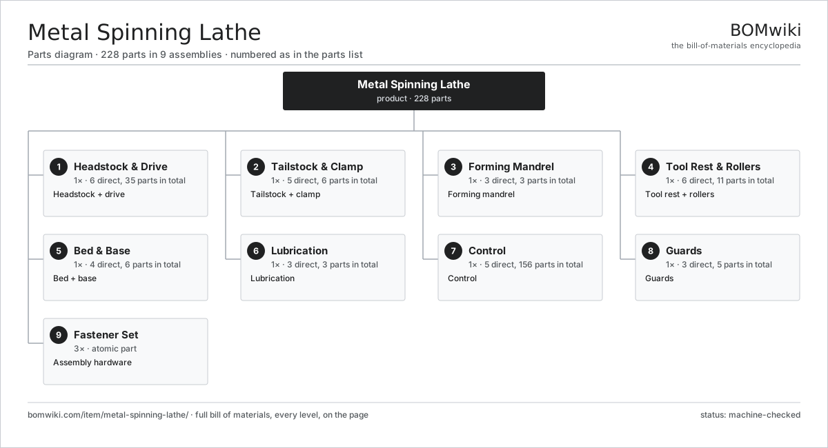
| # | Part | Qty | What it does |
|---|---|---|---|
| 1 | Headstock & Drive 6 parts | 1× | Headstock + drive |
| 2 | Tailstock & Clamp 5 parts | 1× | Tailstock + clamp |
| 3 | Forming Mandrel 3 parts | 1× | Forming mandrel |
| 4 | Tool Rest & Rollers 6 parts | 1× | Tool rest + rollers |
| 5 | Bed & Base 4 parts | 1× | Bed + base |
| 6 | Lubrication 3 parts | 1× | Lubrication |
| 7 | Control 5 parts | 1× | Control |
| 8 | Guards 3 parts | 1× | Guards |
| 9 | Fastener Set | 3× | Assembly hardware |
3D model
No 3D model yet. Have a CAD file of this? Add a 3D model — STL renders right on this page; STEP, FreeCAD, and OpenSCAD sources are welcome too (openly licensed, like all 3D models on BOMwiki).
Build & assembly graph
expand / collapse · shared sub-assemblies converge · links to related products · est. labourTap an assembly to expand/collapse · tap a part to open it · use “Open page” for any node · drag to pan, scroll to zoom.
Bill of materials for Metal Spinning Lathe
9 top-level lines · 57 rows shown · 228 parts total · indented to 3 levels| # | Item / sub-assembly | Part no. | Qty/assy | Ext. qty | Parts | Type |
|---|---|---|---|---|---|---|
| 1 | Headstock & Drive 6 parts | spin-headstock | 1× | 1 | 35 | assembly |
| 1.1 | Main Spindle | spin-spindle | 1× | 1 | · | part |
| 1.2 | Spindle Motor 5 parts | spin-spindle-motor | 1× | 1 | 26 | assembly |
| 1.2.1 | Stator Assembly 3 parts + deeper › | stator-assembly | 1× | 1 | 3 | assembly |
| 1.2.2 | Rotor Assembly 4 parts + deeper › | rotor-assembly | 1× | 1 | 19 | assembly |
| 1.2.3 | Motor Housing | motor-housing | 1× | 1 | · | part |
| 1.2.4 | Ball Bearing | ball-bearing | 2× | 2 | · | part |
| 1.2.5 | Encoder | encoder | 1× | 1 | · | part |
| 1.3 | Drive Belt | drive-belt | 1× | 1 | · | part |
| 1.4 | Faceplate | spin-faceplate | 1× | 1 | · | part |
| 1.5 | Angular Contact Bearing | angular-bearing | 4× | 4 | · | part |
| 1.6 | Oil Seal | oil-seal | 2× | 2 | · | part |
| 2 | Tailstock & Clamp 5 parts | spin-tailstock | 1× | 1 | 6 | assembly |
| 2.1 | Tailstock Body | spin-tailstock-body | 1× | 1 | · | part |
| 2.2 | Quill | spin-tail-quill | 1× | 1 | · | part |
| 2.3 | Follower Block | spin-follower-block | 1× | 1 | · | part |
| 2.4 | Clamp Handwheel | spin-tail-handwheel | 1× | 1 | · | part |
| 2.5 | Ball Bearing | ball-bearing | 2× | 2 | · | part |
| 3 | Forming Mandrel 3 parts | spin-mandrel | 1× | 1 | 3 | assembly |
| 3.1 | Mandrel Body | spin-mandrel-body | 1× | 1 | · | part |
| 3.2 | Mandrel Nose | spin-mandrel-nose | 1× | 1 | · | part |
| 3.3 | Spindle Adapter | spin-mandrel-adapter | 1× | 1 | · | part |
| 4 | Tool Rest & Rollers 6 parts | spin-tool-rest | 1× | 1 | 11 | assembly |
| 4.1 | Rest Bar | spin-rest-bar | 1× | 1 | · | part |
| 4.2 | Fulcrum Pin | spin-fulcrum-pin | 4× | 4 | · | part |
| 4.3 | Forming Roller | spin-forming-roller | 2× | 2 | · | part |
| 4.4 | Beading Roller | spin-beading-roller | 1× | 1 | · | part |
| 4.5 | Trim Tool | spin-trim-tool | 1× | 1 | · | part |
| 4.6 | Roller Arm | spin-roller-arm | 2× | 2 | · | part |
| 5 | Bed & Base 4 parts | spin-bed | 1× | 1 | 6 | assembly |
| 5.1 | Bed Casting | spin-bed-casting | 1× | 1 | · | part |
| 5.2 | Bed Way | spin-bed-way | 2× | 2 | · | part |
| 5.3 | Base Frame | spin-base-frame | 1× | 1 | · | part |
| 5.4 | Fastener Set | fastener-set | 2× | 2 | · | part |
| 6 | Lubrication 3 parts | spin-lubrication | 1× | 1 | 3 | assembly |
| 6.1 | Lube Applicator | spin-lube-applicator | 1× | 1 | · | part |
| 6.2 | Lube Reservoir | spin-lube-reservoir | 1× | 1 | · | part |
| 6.3 | Spindle Oiler | spin-spindle-oiler | 1× | 1 | · | part |
| 7 | Control 5 parts | spin-control | 1× | 1 | 156 | assembly |
| 7.1 | Variable-Frequency Drive 4 parts | spin-vfd | 1× | 1 | 91 | assembly |
| 7.1.1 | Bare PCB | pcb-bare | 1× | 1 | · | part |
| 7.1.2 | IGBT Power Module | igbt-module | 1× | 1 | · | part |
| 7.1.3 | Gate Driver Board 3 parts + deeper › | gate-driver-board | 1× | 1 | 87 | assembly |
| 7.1.4 | DC-Link Capacitor | dc-link-cap | 2× | 2 | · | part |
| 7.2 | Control Panel 4 parts | spin-control-panel | 1× | 1 | 55 | assembly |
| 7.2.1 | Bare PCB | pcb-bare | 1× | 1 | · | part |
| 7.2.2 | Microcontroller | mcu | 1× | 1 | · | part |
| 7.2.3 | Relay | relay | 3× | 3 | · | part |
| 7.2.4 | SMD Passive (R/C/L) | smd-passives | 50× | 50 | · | part |
| 7.3 | Foot Pedal | spin-foot-pedal | 1× | 1 | · | part |
| 7.4 | Wire Bundle | wire-bundle | 1× | 1 | · | part |
| 7.5 | Connector | connector | 8× | 8 | · | part |
| 8 | Guards 3 parts | spin-guards | 1× | 1 | 5 | assembly |
| 8.1 | Sheet Metal Panel | sheet-panel | 3× | 3 | · | part |
| 8.2 | Chip Shield | spin-chip-shield | 1× | 1 | · | part |
| 8.3 | Emergency Stop | spin-estop | 1× | 1 | · | part |
| 9 | Fastener Set | fastener-set | 3× | 3 | · | part |
Related products
same domain, ranked by shared parts CNC Milling Machine
400 parts · shares 6 with this page
Bar Chamfering Machine
1,148 parts · shares 6 with this page
Spring End Grinding Machine
1,048 parts · shares 6 with this page
Centering and Facing Machine
1,419 parts · shares 5 with this page
CNC Milling Machine
400 parts · shares 6 with this page
Bar Chamfering Machine
1,148 parts · shares 6 with this page
Spring End Grinding Machine
1,048 parts · shares 6 with this page
Centering and Facing Machine
1,419 parts · shares 5 with this page
 CNC Lathe
511 parts · shares 5 with this page
CNC Lathe
511 parts · shares 5 with this page
Sourcing: possible vendors
Prices, MOQ, and lead times are algorithmic estimates, not quotes, and not claims about these companies. Company mappings are curated by keyword; est. price band $10k–$1M. How estimates work| Vendor | HQ | Specialty | MOQ | Lead time |
|---|---|---|---|---|
|
🇩🇪DMG MORI
dmgmori.com ↗
|
Bielefeld, DE | Machine tools | 5 units | 12–20 wks |
|
🇯🇵Mazak
mazak.com ↗
|
Oguchi, JP | Machine tools | 5 units | 12–20 wks |
| haascnc.com ↗ | Oxnard, US | CNC machine tools | 5 units | 12–20 wks |
|
🇯🇵Okuma
okuma.com ↗
|
Niwa, JP | Machine tools | 5 units | 12–20 wks |
|
🇩🇪Trumpf
trumpf.com ↗
|
Ditzingen, DE | Laser & sheet-metal machines | 5 units | 12–20 wks |
862-word article